EP2085354A1 - Appareil générateur d'hydrogène et système de pile à combustible - Google Patents
Appareil générateur d'hydrogène et système de pile à combustible Download PDFInfo
- Publication number
- EP2085354A1 EP2085354A1 EP07806591A EP07806591A EP2085354A1 EP 2085354 A1 EP2085354 A1 EP 2085354A1 EP 07806591 A EP07806591 A EP 07806591A EP 07806591 A EP07806591 A EP 07806591A EP 2085354 A1 EP2085354 A1 EP 2085354A1
- Authority
- EP
- European Patent Office
- Prior art keywords
- carbon monoxide
- monoxide reducer
- preheat
- reformed gas
- evaporator
- Prior art date
- Legal status (The legal status is an assumption and is not a legal conclusion. Google has not performed a legal analysis and makes no representation as to the accuracy of the status listed.)
- Granted
Links
Images


Classifications
-
- C—CHEMISTRY; METALLURGY
- C01—INORGANIC CHEMISTRY
- C01B—NON-METALLIC ELEMENTS; COMPOUNDS THEREOF; METALLOIDS OR COMPOUNDS THEREOF NOT COVERED BY SUBCLASS C01C
- C01B3/00—Hydrogen; Gaseous mixtures containing hydrogen; Separation of hydrogen from mixtures containing it; Purification of hydrogen; Reversible storage of hydrogen
- C01B3/02—Production of hydrogen; Production of gaseous mixtures containing hydrogen
- C01B3/32—Production of hydrogen; Production of gaseous mixtures containing hydrogen by reaction of gaseous or liquid organic compounds with gasifying agents, e.g. water, carbon dioxide or air
- C01B3/34—Production of hydrogen; Production of gaseous mixtures containing hydrogen by reaction of gaseous or liquid organic compounds with gasifying agents, e.g. water, carbon dioxide or air by reaction of hydrocarbons with gasifying agents
- C01B3/38—Production of hydrogen; Production of gaseous mixtures containing hydrogen by reaction of gaseous or liquid organic compounds with gasifying agents, e.g. water, carbon dioxide or air by reaction of hydrocarbons with gasifying agents using catalysts
- C01B3/384—Production of hydrogen; Production of gaseous mixtures containing hydrogen by reaction of gaseous or liquid organic compounds with gasifying agents, e.g. water, carbon dioxide or air by reaction of hydrocarbons with gasifying agents using catalysts with external heating of the catalyst
-
- B—PERFORMING OPERATIONS; TRANSPORTING
- B01—PHYSICAL OR CHEMICAL PROCESSES OR APPARATUS IN GENERAL
- B01J—CHEMICAL OR PHYSICAL PROCESSES, e.g. CATALYSIS OR COLLOID CHEMISTRY; THEIR RELEVANT APPARATUS
- B01J8/00—Chemical or physical processes in general, conducted in the presence of fluids and solid particles; Apparatus for such processes
- B01J8/02—Chemical or physical processes in general, conducted in the presence of fluids and solid particles; Apparatus for such processes with stationary particles, e.g. in fixed beds
- B01J8/04—Chemical or physical processes in general, conducted in the presence of fluids and solid particles; Apparatus for such processes with stationary particles, e.g. in fixed beds the fluid passing successively through two or more beds
- B01J8/0446—Chemical or physical processes in general, conducted in the presence of fluids and solid particles; Apparatus for such processes with stationary particles, e.g. in fixed beds the fluid passing successively through two or more beds the flow within the beds being predominantly vertical
- B01J8/0461—Chemical or physical processes in general, conducted in the presence of fluids and solid particles; Apparatus for such processes with stationary particles, e.g. in fixed beds the fluid passing successively through two or more beds the flow within the beds being predominantly vertical in two or more cylindrical annular shaped beds
- B01J8/0465—Chemical or physical processes in general, conducted in the presence of fluids and solid particles; Apparatus for such processes with stationary particles, e.g. in fixed beds the fluid passing successively through two or more beds the flow within the beds being predominantly vertical in two or more cylindrical annular shaped beds the beds being concentric
-
- B—PERFORMING OPERATIONS; TRANSPORTING
- B01—PHYSICAL OR CHEMICAL PROCESSES OR APPARATUS IN GENERAL
- B01J—CHEMICAL OR PHYSICAL PROCESSES, e.g. CATALYSIS OR COLLOID CHEMISTRY; THEIR RELEVANT APPARATUS
- B01J8/00—Chemical or physical processes in general, conducted in the presence of fluids and solid particles; Apparatus for such processes
- B01J8/02—Chemical or physical processes in general, conducted in the presence of fluids and solid particles; Apparatus for such processes with stationary particles, e.g. in fixed beds
- B01J8/04—Chemical or physical processes in general, conducted in the presence of fluids and solid particles; Apparatus for such processes with stationary particles, e.g. in fixed beds the fluid passing successively through two or more beds
- B01J8/0446—Chemical or physical processes in general, conducted in the presence of fluids and solid particles; Apparatus for such processes with stationary particles, e.g. in fixed beds the fluid passing successively through two or more beds the flow within the beds being predominantly vertical
- B01J8/0461—Chemical or physical processes in general, conducted in the presence of fluids and solid particles; Apparatus for such processes with stationary particles, e.g. in fixed beds the fluid passing successively through two or more beds the flow within the beds being predominantly vertical in two or more cylindrical annular shaped beds
- B01J8/0469—Chemical or physical processes in general, conducted in the presence of fluids and solid particles; Apparatus for such processes with stationary particles, e.g. in fixed beds the fluid passing successively through two or more beds the flow within the beds being predominantly vertical in two or more cylindrical annular shaped beds the beds being superimposed one above the other
-
- B—PERFORMING OPERATIONS; TRANSPORTING
- B01—PHYSICAL OR CHEMICAL PROCESSES OR APPARATUS IN GENERAL
- B01J—CHEMICAL OR PHYSICAL PROCESSES, e.g. CATALYSIS OR COLLOID CHEMISTRY; THEIR RELEVANT APPARATUS
- B01J8/00—Chemical or physical processes in general, conducted in the presence of fluids and solid particles; Apparatus for such processes
- B01J8/02—Chemical or physical processes in general, conducted in the presence of fluids and solid particles; Apparatus for such processes with stationary particles, e.g. in fixed beds
- B01J8/04—Chemical or physical processes in general, conducted in the presence of fluids and solid particles; Apparatus for such processes with stationary particles, e.g. in fixed beds the fluid passing successively through two or more beds
- B01J8/0496—Heating or cooling the reactor
-
- H—ELECTRICITY
- H01—ELECTRIC ELEMENTS
- H01M—PROCESSES OR MEANS, e.g. BATTERIES, FOR THE DIRECT CONVERSION OF CHEMICAL ENERGY INTO ELECTRICAL ENERGY
- H01M8/00—Fuel cells; Manufacture thereof
- H01M8/06—Combination of fuel cells with means for production of reactants or for treatment of residues
- H01M8/0606—Combination of fuel cells with means for production of reactants or for treatment of residues with means for production of gaseous reactants
- H01M8/0612—Combination of fuel cells with means for production of reactants or for treatment of residues with means for production of gaseous reactants from carbon-containing material
- H01M8/0625—Combination of fuel cells with means for production of reactants or for treatment of residues with means for production of gaseous reactants from carbon-containing material in a modular combined reactor/fuel cell structure
- H01M8/0631—Reactor construction specially adapted for combination reactor/fuel cell
-
- B—PERFORMING OPERATIONS; TRANSPORTING
- B01—PHYSICAL OR CHEMICAL PROCESSES OR APPARATUS IN GENERAL
- B01J—CHEMICAL OR PHYSICAL PROCESSES, e.g. CATALYSIS OR COLLOID CHEMISTRY; THEIR RELEVANT APPARATUS
- B01J2208/00—Processes carried out in the presence of solid particles; Reactors therefor
- B01J2208/00008—Controlling the process
- B01J2208/00017—Controlling the temperature
- B01J2208/00477—Controlling the temperature by thermal insulation means
- B01J2208/00495—Controlling the temperature by thermal insulation means using insulating materials or refractories
-
- B—PERFORMING OPERATIONS; TRANSPORTING
- B01—PHYSICAL OR CHEMICAL PROCESSES OR APPARATUS IN GENERAL
- B01J—CHEMICAL OR PHYSICAL PROCESSES, e.g. CATALYSIS OR COLLOID CHEMISTRY; THEIR RELEVANT APPARATUS
- B01J2208/00—Processes carried out in the presence of solid particles; Reactors therefor
- B01J2208/00008—Controlling the process
- B01J2208/00017—Controlling the temperature
- B01J2208/00504—Controlling the temperature by means of a burner
-
- C—CHEMISTRY; METALLURGY
- C01—INORGANIC CHEMISTRY
- C01B—NON-METALLIC ELEMENTS; COMPOUNDS THEREOF; METALLOIDS OR COMPOUNDS THEREOF NOT COVERED BY SUBCLASS C01C
- C01B2203/00—Integrated processes for the production of hydrogen or synthesis gas
- C01B2203/02—Processes for making hydrogen or synthesis gas
- C01B2203/0205—Processes for making hydrogen or synthesis gas containing a reforming step
- C01B2203/0227—Processes for making hydrogen or synthesis gas containing a reforming step containing a catalytic reforming step
- C01B2203/0233—Processes for making hydrogen or synthesis gas containing a reforming step containing a catalytic reforming step the reforming step being a steam reforming step
-
- C—CHEMISTRY; METALLURGY
- C01—INORGANIC CHEMISTRY
- C01B—NON-METALLIC ELEMENTS; COMPOUNDS THEREOF; METALLOIDS OR COMPOUNDS THEREOF NOT COVERED BY SUBCLASS C01C
- C01B2203/00—Integrated processes for the production of hydrogen or synthesis gas
- C01B2203/04—Integrated processes for the production of hydrogen or synthesis gas containing a purification step for the hydrogen or the synthesis gas
- C01B2203/0465—Composition of the impurity
- C01B2203/047—Composition of the impurity the impurity being carbon monoxide
-
- C—CHEMISTRY; METALLURGY
- C01—INORGANIC CHEMISTRY
- C01B—NON-METALLIC ELEMENTS; COMPOUNDS THEREOF; METALLOIDS OR COMPOUNDS THEREOF NOT COVERED BY SUBCLASS C01C
- C01B2203/00—Integrated processes for the production of hydrogen or synthesis gas
- C01B2203/06—Integration with other chemical processes
- C01B2203/066—Integration with other chemical processes with fuel cells
-
- C—CHEMISTRY; METALLURGY
- C01—INORGANIC CHEMISTRY
- C01B—NON-METALLIC ELEMENTS; COMPOUNDS THEREOF; METALLOIDS OR COMPOUNDS THEREOF NOT COVERED BY SUBCLASS C01C
- C01B2203/00—Integrated processes for the production of hydrogen or synthesis gas
- C01B2203/08—Methods of heating or cooling
- C01B2203/0805—Methods of heating the process for making hydrogen or synthesis gas
- C01B2203/0811—Methods of heating the process for making hydrogen or synthesis gas by combustion of fuel
-
- C—CHEMISTRY; METALLURGY
- C01—INORGANIC CHEMISTRY
- C01B—NON-METALLIC ELEMENTS; COMPOUNDS THEREOF; METALLOIDS OR COMPOUNDS THEREOF NOT COVERED BY SUBCLASS C01C
- C01B2203/00—Integrated processes for the production of hydrogen or synthesis gas
- C01B2203/08—Methods of heating or cooling
- C01B2203/0805—Methods of heating the process for making hydrogen or synthesis gas
- C01B2203/0811—Methods of heating the process for making hydrogen or synthesis gas by combustion of fuel
- C01B2203/0822—Methods of heating the process for making hydrogen or synthesis gas by combustion of fuel the fuel containing hydrogen
-
- C—CHEMISTRY; METALLURGY
- C01—INORGANIC CHEMISTRY
- C01B—NON-METALLIC ELEMENTS; COMPOUNDS THEREOF; METALLOIDS OR COMPOUNDS THEREOF NOT COVERED BY SUBCLASS C01C
- C01B2203/00—Integrated processes for the production of hydrogen or synthesis gas
- C01B2203/08—Methods of heating or cooling
- C01B2203/0805—Methods of heating the process for making hydrogen or synthesis gas
- C01B2203/0811—Methods of heating the process for making hydrogen or synthesis gas by combustion of fuel
- C01B2203/0827—Methods of heating the process for making hydrogen or synthesis gas by combustion of fuel at least part of the fuel being a recycle stream
-
- Y—GENERAL TAGGING OF NEW TECHNOLOGICAL DEVELOPMENTS; GENERAL TAGGING OF CROSS-SECTIONAL TECHNOLOGIES SPANNING OVER SEVERAL SECTIONS OF THE IPC; TECHNICAL SUBJECTS COVERED BY FORMER USPC CROSS-REFERENCE ART COLLECTIONS [XRACs] AND DIGESTS
- Y02—TECHNOLOGIES OR APPLICATIONS FOR MITIGATION OR ADAPTATION AGAINST CLIMATE CHANGE
- Y02E—REDUCTION OF GREENHOUSE GAS [GHG] EMISSIONS, RELATED TO ENERGY GENERATION, TRANSMISSION OR DISTRIBUTION
- Y02E60/00—Enabling technologies; Technologies with a potential or indirect contribution to GHG emissions mitigation
- Y02E60/30—Hydrogen technology
- Y02E60/50—Fuel cells
-
- Y—GENERAL TAGGING OF NEW TECHNOLOGICAL DEVELOPMENTS; GENERAL TAGGING OF CROSS-SECTIONAL TECHNOLOGIES SPANNING OVER SEVERAL SECTIONS OF THE IPC; TECHNICAL SUBJECTS COVERED BY FORMER USPC CROSS-REFERENCE ART COLLECTIONS [XRACs] AND DIGESTS
- Y02—TECHNOLOGIES OR APPLICATIONS FOR MITIGATION OR ADAPTATION AGAINST CLIMATE CHANGE
- Y02P—CLIMATE CHANGE MITIGATION TECHNOLOGIES IN THE PRODUCTION OR PROCESSING OF GOODS
- Y02P20/00—Technologies relating to chemical industry
- Y02P20/10—Process efficiency
Definitions
- the present invention relates to a hydrogen generator for producing hydrogen-rich reformed gas, using hydrocarbon-based fuel such as city gas or LPG as a material gas.
- the present invention also relates to a fuel cell system equipped with a fuel cell for generating electric power from hydrogen produced by the hydrogen generator.
- the passage 22 is in contact with the outer periphery of the carbon monoxide reducer 10.
- the material gas and water sent to the passage 22 are heated by the reaction heat of the carbon monoxide reducer 10 and then introduced into the shift convertor 8 as a mixture gas of the material gas and steam.
- the reformer 8 is heated by the burner 20, so that a steam reforming reaction occurs between the material gas and the steam by the action of the reforming catalyst, generating hydrogen-rich reformed gas.
- the reformed gas generated in the reformer 8 is sent to the carbon monoxide reducer 10 by way of a passage 25 and carbon monoxide is removed from the reformed gas through a CO shift reaction by the action of the CO shifting catalyst.
- the reformed gas from which carbon monoxide has been removed is taken out of an outlet port 26.
- the outer periphery of the carbon monoxide reducer 10 is provided with the passage 22 for recovering the heat of the exothermic reaction that takes place in the carbon monoxide reducer 10 and the water passing through the passage 22 is evaporated by heating. Therefore, the outer periphery of the carbon monoxide reducer 10 is cooled by the water during the heat exchange, which may cause a temperature distribution that significantly varies in its thickness direction (radial direction) with low temperatures at the outer periphery of the carbon monoxide reducer 10 and high temperatures at the inner periphery.
- a heat insulating layer may be disposed so as to enclose the cylindrical body. According to this configuration, the temperature distribution in the thickness direction of the carbon monoxide reducer can be further reduced by the heat insulating function of the heat insulating layer.
- the heat transmission buffering space may be in communication with a passage for the reformed gas flowing out of the carbon monoxide reducer.
- a portion of the carbon monoxide reducer defining partition wall which portion faces the preheat-evaporator defining partition wall may be made of metal, and an extension portion thereof may be joined to the preheat-evaporator defining partition wall at the upstream side of the carbon monoxide reducer in the flow of the reformed gas.
- the reformed gas flowing in the heat transmission buffering space may change its flowing direction from the opposite direction to the same direction relative to the flowing direction of the reformed gas in the carbon monoxide reducer at a position which is located between the upstream end and downstream end of the carbon monoxide reducer in the flowing direction of the gas in the carbon monoxide reducer, the position being set based on the filling quantity of the carbon monoxide removing catalyst.
- the cooling of the upstream portion of the carbon monoxide reducer; the reduction of the temperature distribution in the downstream position in its thickness direction; and heat utilization can be effectively carried out in accordance with the filling quantity and type of the carbon monoxide removing catalyst.
- the reformed gas flowing in the heat transmission buffering space may change its flowing direction from the opposite direction to the same direction relative to the flowing direction of the reformed gas in the carbon monoxide reducer at a position which is located between the upstream end of the carbon monoxide reducer with respect to the flowing direction of the gas in the carbon monoxide reducer and a position that is apart from the upstream end by substantially one fourth of the length of the carbon monoxide reducer.
- the heat exchange with the reformed gas flowing from the carbon monoxide reducer can be more effectively performed.
- An air feeding path may be formed for feeding air to a passage for the reformed gas that flows into the carbon monoxide reducer, and the carbon monoxide removing catalyst may be a selective oxidation catalyst.
- the carbon monoxide removing catalyst may be a selective oxidation catalyst.
- the invention also provides a fuel cell system comprising the hydrogen generator described in any one of claims 1 to 15 and a fuel cell for generating electric power by use of the reformed gas fed from the hydrogen generator and hydrogen-containing oxidizing gas.
- a fuel cell system comprising the hydrogen generator described in any one of claims 1 to 15 and a fuel cell for generating electric power by use of the reformed gas fed from the hydrogen generator and hydrogen-containing oxidizing gas.
- the heat transmission buffering section provided between the carbon monoxide reducer and the preheat-evaporator mitigates cooling of the preheat-evaporator side of the carbon monoxide reducer to prevent an increase in the temperature difference between the preheat-evaporator side of the carbon monoxide reducer and its opposite side, so that variations in the temperature distribution in the thickness direction of the carbon monoxide reducer can be reduced and, in consequence, carbon monoxide contained in the reformed gas can be stably reduced.
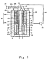
- Fig. 1 is a sectional view that schematically shows a configuration of a hydrogen generator and a fuel cell system according to a first embodiment of the invention.
- the system of this embodiment has a cylindrical body 3 that serves as a casing thereof.
- the cylindrical body 3 has a concentric double circular-cylindrical structure composed of an inner cylinder (partition wall) 1 and an outer cylinder (partition wall) 2 with their axes extending in a vertical direction. The upper and lower ends of the cylindrical body 3 are closed.
- a combustor 4 constituted by a burner is provided at the center of the inside of the inner cylinder 1, and a combustion gas passage 5 is formed between the combustor 4 and the inner cylinder 1 so as to extend along the inner periphery of the inner cylinder 1.
- the combustion gas passage 5 is in communication with the outside (the atmosphere) through an outlet (not shown).
- a cylindrical space formed between the large diameter portion 30b of the partition cylinder 30 and the inner cylinder 1 and a reforming catalyst 7 that fills up this space constitute a reformer 8.
- An outlet 34 is provided to open in the large diameter portion 30b of the partition cylinder 30 that defines the outer periphery of the lower end portion of the reformer 8.
- a cylindrical carbon monoxide reducer 10 is disposed at the inner periphery of the upper portion of the outer cylinder 2 so as to enclose the preheat-evaporator 6.
- a separating wall (partition wall) 47 is formed within the cylindrical body 3, which is composed of a cylindrical vertical wall 47a extending from the upper wall of the cylinder body 3 downwardly along the upper portion of the outer cylinder 2 and an annular horizontal wall 47b extending horizontally from the lower end of the vertical wall 47a to the outer cylinder 2.
- the space defined by the separating wall 47, the upper wall of the cylinder body 3 and the upper portion of the outer cylinder 2 and a carbon monoxide removing catalyst 9 filling this space constitute the carbon monoxide reducer 10.
- the horizontal wall 47b of the separating wall 47 that defines the lower end of the carbon monoxide reducer 10 is provided with an open inlet 36, whereas the upper wall of the cylindrical body 3 that defines the upper end is provided with an outlet 37.
- This outlet 37 is connected to a fuel cell 14 through a reformed gas feeding pipe 38.
- the carbon monoxide reducer 10 described herein serves as a shift converter for removing carbon monoxide through a CO shift reaction using a CO shifting catalyst as the carbon monoxide removing catalyst 9
- a selective oxidization device at the stage subsequent to the shift converter, which device removes carbon monoxide through a CO selective oxidization using a CO selective oxidation catalyst as the carbon monoxide removing catalyst 9.
- the vertical wall 47a of the separating wall 47 that defines the carbon monoxide reducer section 10 is opposed to the small diameter portion 30a of the partition cylinder 30 that defines the preheat-evaporator 6, with a certain small spacing therebetween.
- the small diameter portion 30a of the partition cylinder 30, the vertical wall 47a of the separating wall 47 and the space (hereinafter referred to as "heat transmission buffering space") 48 between them constitute a heat transmission buffering section 11 between the preheat-evaporator 6 and the carbon monoxide reducer 10.
- the heat transmission buffering space 48 is communicated, at its lower end thereof, with a cylindrical reformed gas passage 40 that is a space between the reformer 8 and the outer cylinder 2.
- Water fed from the water feeder 32 and the hydrocarbon-based material gas such as city gas or LPG fed from the material gas feeding section 31 through the material gas feeding pipe 33a firstly enter the preheat-evaporator 6.
- the preheat-evaporator 6 is heated by the combustion gas through the inner cylinder 1 which combustion gas is flowing in the combustion gas passage 5.
- the reaction heat generated by the CO shift reaction or the CO selective oxidation reaction in the carbon monoxide reducer 10 is transmitted to the preheat-evaporator 6 through the heat transmission buffering section 11, so that the preheat-evaporator 6 is also heated by the heat transmitted from the carbon monoxide reducer 10.
- the material gas and water are heated when passing through the preheat-evaporator 6, so that a mixed gas containing the material gas and steam exuded from the water is produced.
- This mixed gas flows into the reformer 8 and the material gas and steam cause a steam reforming reaction with the catalytic action of the reforming catalyst 7, so that hydrogen-rich reformed gas is generated. Since the steam reforming reaction is an endothermic reaction, the reformer 8 is maintained at temperatures within the range of 600 to 700°C that are reforming reaction temperatures, by heating the reformer 8 with the combustion gas flowing in the combustion gas passage 5.
- the reformed gas generated in the reformer 8 flows from the outlet 34 at the lower end of the reformer 8 into the reformed gas passage 40 and exchanges heat with the reformer 8 when moving upward in the reformed gas passage 40 so that its temperature drops to about 280°C.
- the reformed gas flows into the carbon monoxide reducer 10 from the inlet 36 provided at the lower end thereof so that carbon monoxide contained in the reformed gas is removed as carbon dioxide by the catalytic action of the carbon monoxide removing catalyst 9.
- the carbon monoxide reducer 10 is composed of a shift converter that removes carbon monoxide through a CO shift reaction, it is desirable in view of reaction speed and reaction equilibrium that the carbon monoxide reducer 10 have a temperature gradient that varies in the flowing direction of the reformed gas with a temperature of about 280°C at the inlet 36 and a temperature of about 200°C at the outlet 37.
- the carbon monoxide reducer 10 is opposed to the preheat-evaporator 6 in parallel with the flowing direction of the reformed gas and exchanges heat with the water flowing in the preheat-evaporator 6.
- the portion of the carbon monoxide reducer 10 closer to the outlet 37 is closer to the upstream of the flow of water in the preheat-evaporator 6 and therefore a larger amount of heat is exchanged thereat. Accordingly, the CO shift reaction heat of the reformed gas, which has a temperature of about 280°C and is flowing from the inlet 36 to the carbon monoxide reducer 10, is cooled by the heat exchange with the preheat-evaporator 6 so that the temperature of the reformed gas drops to about 200°C at the outlet 37.
- the temperature gradient of the carbon monoxide reducer 10 is set to vary in the flowing direction of the reformed gas such that the temperature of the upstream side is higher than that of the downstream side.
- the carbon monoxide reducer 10 has a selective oxidization device that is provided at the stage subsequent to the reformer, for removing carbon monoxide by a CO selective oxidation reaction.
- the exothermic heat of the CO selective oxidation reaction is suppressed by the heat exchange between the reformed gas flowing in the selective oxidation device and water flowing in the preheat-evaporator 6 to thereby make the temperature of the selective oxidation device be a desirable value, i.e., about 150°C.
- the heat transmission buffering section 11 that is constituted by the two partition walls, i.e., the small diameter portion 30a of the partition cylinder 30 and the vertical wall 47a of the separating wall 47 and by the space 48 between these two partition walls.
- the carbon monoxide reducer 10 and the preheat-evaporator 6 in this embodiment do not contact each other with only one partition wall therebetween.
- the preheat-evaporator 6 side of the carbon monoxide reducer 10 can be prevented from excessively dropping in temperature by excessive cooling by the heat exchange with the water; the difference in temperature between the preheat-evaporator 6 side of the carbon monoxide reducer 10 and its opposite side can be prevented from becoming significant; and the temperature distribution of the carbon monoxide reducer 10 in its thickness direction (i.e., a direction perpendicular to the flowing direction of the reformed gas, that is, a radial direction of the cylindrical body 3) do not become significant and can be reduced. Meanwhile, the preheat-evaporator 6 is heated by the combustion gas through the inner cylinder 1 which combustion gas is flowing in the combustion gas passage 5. Therefore, even though the amount of heat transmitted from the carbon monoxide reducer 10 is thus suppressed, a sufficient amount of heat necessary for evaporating the water can be ensured.
- the temperature gradient of the carbon monoxide reducer 10 in the flowing direction of the reformed gas can be properly set as described earlier while reducing variations in the temperature distribution in the thickness direction of the carbon monoxide reducer 10, so that carbon monoxide can be stably removed from the reformed gas with high efficiency.
- the carbon monoxide reducer 10 is constituted by a shift converter and a selective oxidation device
- the CO concentration (about 10%) of the reformed gas generated by the reformer 8 can be reduced to about 0.5% by the shift converter and to about 10 ppm by the selective oxidation device.
- the hydrogen-rich reformed gas from which carbon monoxide has been removed by the carbon monoxide reducer 10, is fed from the inlet 37 to the fuel cell 14 through the reformed gas feeding pipe 38, and electric power is generated using hydrogen contained in the reformed gas and oxygen-containing oxidizing gas such as air.
- a reformed gas return pipe 41 is connected between the fuel cell 14 and the material gas feeding pipe 33b, and the reformed gas which has not been consumed in the fuel cell 14 is fed from the reformed gas return pipe 41 to the combustor 4 through the material gas feeding pipe 33b.
- the hydrogen generator of the invention since the reformed gas, from which carbon monoxide has been stably removed, can be sent out as described above, there is no chance that the catalyst of the fuel cell 14 deteriorates owing to poisoning by carbon monoxide and stable power generation can be performed over a long period of time in the fuel cell 14.
- the heat transmission buffering space 48 is formed as a space inside the cylindrical body 3 such that the space 48 is communicated at the lower end thereof with the reformed gas passage 40. Therefore, the reformed gas generated in the reformer 8 can flow into the heat transmission buffering section 11 through the reformed gas passage 40.
- the reformed gas contains steam and if this steam is condensed into water, the condensed water will flow from the heat transmission buffering space 48 into the reformed gas passage 40, so that no condensed water stagnation occurs in the heat transmission buffering space 48.
- the heat insulating layer 13 is provided so as to enclose the cylindrical body 3, thereby insulating the external side of the carbon monoxide reducer 10.
- Fig. 6(a) shows the result of a two-dimensional thermo-fluid reaction simulation conducted on a model (Comparative Example) prepared by modifying the hydrogen generator shown in Fig. 1 such that the preheat-evaporator 6 and the carbon monoxide reducer 10 are brought into direct contact with each other without interposing the heat transmission buffering section 11 therebetween.
- the simulation was made on assumption that the height of the carbon monoxide reducer 10 was set to 100mm, the temperature of the gas flowing into the carbon monoxide reducer 10 was set to 250°C, and the internal side of the carbon monoxide reducer 10 was cooled by steam. Temperatures at the internal side, center and external side of the carbon monoxide reducer 10 in the thickness direction are shown in Fig. 6(a) .
- the internal side of the carbon monoxide reducer 10 was excessively cooled and the temperature of the carbon monoxide reducer 10 significantly varies in its thickness direction, and the maximum temperature difference in the temperature distribution in the thickness direction was estimated to be about 65°C.
- Fig. 6(b) shows the result of a two-dimensional thermo-fluid reaction simulation conducted on a model that is the hydrogen generator shown in Fig. 1 having the heat transmission buffering section 11 between the preheat-evaporator 6 and the carbon monoxide reducer 10.
- This simulation was made on assumption that the height of the carbon monoxide reducer 10 was 100mm, the height of the flow control section 11 was 100mm, the temperature of the gas flowing into the carbon monoxide reducer 10 was 250°C, the flow rate of the inflow gas was equivalent to 1 kW power generation, and the internal side of the heat transmission buffering section 11 was cooled by steam. Temperatures at the internal side, center and external side of the carbon monoxide reducer 10 in the thickness direction are shown in Fig.
- Fig. 2 is a sectional view that schematically shows a configuration of a hydrogen generator and a fuel cell system according to a second embodiment of the invention.
- the heat transmission buffering space 48 is covered with the a cover plate 44 at the lower end thereof to inhibit communication with the reformed gas passage 40, and a communication port 43 is provided at the upper part of the vertical wall 47a of the separating wall 47 that defines the inner periphery of the carbon monoxide reducer 10 to allow communication between the heat transmission buffering space 48 and the carbon monoxide reducer 10.
- the other configuration is the same as that of Fig. 1 .
- the heat transmission buffering space 48 and the carbon monoxide reducer 10 are communicated with each other through the communication port 43, the reformed gas of low CO concentration from which carbon monoxide has been removed by the carbon monoxide reducer 10 stagnates in the heat transmission buffering space 48.
- the reformed gas stagnating in the heat transmission buffering space 48 exchanges heat with the water in the preheat-evaporator 6, and therefore drops in temperature.
- the reaction of the carbon monoxide reducer 10 will be adversely affected because the reformed gas, which has flown out of the reformer 8 and has high CO concentration, is stagnating in the heat transmission buffering space 48.
- the reformed gas stagnating in the heat transmission buffering space 48 is of low CO concentration and therefore the reformed gas, which has dropped in temperature, will not affect the reaction of the carbon monoxide reducer 10 even if it flows into the carbon monoxide reducer 10. Accordingly, the second embodiment enables more stable carbon monoxide removal, compared to the first embodiment shown in Fig. 1 .
- Fig. 3 is a sectional view that schematically shows a configuration of a hydrogen generator and a fuel cell system according to a third embodiment of the invention.
- the heat transmission buffering space 48 is covered with the cover plate 44 at the lower end thereof to inhibit communication with the reformed gas passage 40, and the upper wall of the cylindrical body 3 that defines the upper end of the heat transmission buffering space 48 is opened to allow communication between the heat transmission buffering space 48 and the outside of the cylindrical body 3.
- the heat transmission buffering space 48 is isolated from the inside of the cylindrical body 3.
- the heat transmission buffering space 48 is filled with a heat transmission member 12.
- the heat transmission member 12 is made of, for example, a metal having a suitably selected heat conductivity.
- the other configuration is the same as that of Fig. 1 .
- the cylindrical heat transmission member 12 is detachably attached by inserting it into the heat transmission buffering space 48 in this embodiment, the invention is not necessarily limited to such a configuration.
- the heat transmission buffering space 48 By filling the heat transmission buffering space 48 with the heat transmission member 12 in this way, cooling of the preheat-evaporator 6 side of the carbon monoxide reducer 10 can be accelerated owing to the heat transmission action of the heat transmission member 12.
- the inflow temperature and outflow temperature of the carbon monoxide reducer 10 are adjusted by selectively employing materials having different heat conductivities as the heat transmission member 12 or changing the arrangement of the heat transmission member 12, so that proper setting of the temperature gradient of the carbon monoxide reducer 10 in the flowing direction of the reformed gas can be facilitated.
- the heat transmission member 12 may be arranged so as to fill the heat transmission buffering space 48.
- the reformed gas does not flow into the heat transmission buffering space 48, so that the reformed gas does not stagnate in the heat transmission buffering space 48.
- purging is performed by replacing the gas present between the inner cylinder 1 and outer cylinder 2 of the cylindrical body 3 with purge gas prior to start-up of the hydrogen generator, the purging can be effectively carried out, because no reformed gas stagnates in the heat transmission buffering space 48. This enables it to reduce the amount of purge gas to be used thereby reducing the energy loss particularly in cases where city gas or LPG is used as the purge gas.
- Fig. 4 is a sectional view that schematically shows a configuration of a hydrogen generator and a fuel cell system according to a fourth embodiment of the invention.
- the lower part of the vertical wall 47a of the separating wall 47 projects inward, thereby forming a projecting portion 46 that extends over the entire inner periphery of the lower part of the carbon monoxide reducer 10, so the heat transmission buffering space 48 is small in width (thickness) in the lower part of the carbon monoxide reducer 10 and large in width in the upper part thereof.
- a sufficient amount of reaction heat is recovered by the water of the preheat-evaporator 6 at the upstream side of the carbon monoxide reducer 10, and excessive cooling to a specified temperature or lower is avoided while reducing variations in the temperature distribution in the thickness direction at the downstream side of the carbon monoxide reducer 10.
- Fig. 5 is a sectional view that schematically shows a configuration of a hydrogen generator and a fuel cell system according to a fifth embodiment of the invention.
- the fifth embodiment is constructed by modifying the fourth embodiment such that the projecting portion 46 formed at the lower inner peripheral part of the carbon monoxide reducer 10 is positioned adjacently to the preheat-evaporator 6 with the partition cylinder 30 therebetween, so that the heat transmission buffering section 11 is not formed between them.
- the vertical wall 47a of the separating wall 47 extends downward from the upper wall of the cylindrical body 3 to a position that is about a half of the entire height (entire length) of the carbon monoxide reducer 10 and then extends horizontally inward so as to be joined to the partition cylinder 30 (the portion that extends horizontally (hereinafter referred to as "horizontally extending portion”) corresponds to the extension portion (of the vertical wall 47a) stated in the claims).
- Reference numeral 50 designates the joint where the horizontally extending portion of the vertical wall 47a joins the partition cylinder 30.
- the upstream portion of the carbon monoxide reducer 10 exchanges heat with the preheat-evaporator 6 through only the partition cylinder 30, not only excessive heating at the upstream portion can be prevented but also the heat recovery efficiency of the water in the preheat-evaporator 6 can be increased.
- the carbon monoxide reducer 10 is excessively heated to 300°C or more in cases where a copper and zinc-based catalyst is used as the shifting catalyst of the carbon monoxide reducer 10, thermal degradation occurs in the catalyst, which adversely affects the performance of the catalyst.
- Such excessive heating can be prevented to maintain the durability of the shifting catalyst, by carrying out the heat exchange between the upstream portion corresponding to a high temperature portion of the carbon monoxide reducer 10 and the preheat-evaporator 6 with one partition wall (partition cylinder 30) interposed therebetween. Additionally, in the downstream portion of the carbon monoxide reducer 10, the amount of exchanged heat is restricted by the heat transmission buffering section 11, thereby preventing excessive cooling to a specified temperature or lower while reducing variations in the temperature distribution in the thickness direction.
- Fig. 8 is a sectional view that schematically shows a configuration of a hydrogen generator and a fuel cell system according to a sixth embodiment of the invention.
- the sixth embodiment is the best mode obtained by modifying the fifth embodiment ( Fig. 5 ).
- the vertical wall 47a of the separating wall 47 is made of metal (e.g., stainless steel).
- the vertical wall 47a of the separating wall 47 has the shape of a flanged cylinder and its upper end is a specified distance apart from the upper wall of the cylindrical body 3.
- the vertical wall 47a downwardly extends from its upper end by approximately three fourth of the distance between the upper end position and the horizontal wall 47b of the separating wall 47 and then extends horizontally inward to be joined to the partition cylinder 30 (this horizontally extending portion corresponds to the extension portion (of the vertical wall 47a) stated in the claims).
- the space defined by the cylindrical body 3, the vertical wall 47a of the separating wall 47, the partition cylinder 30 and the horizontal wall 47b of the separating wall 47 and the carbon monoxide removing catalyst 9 filled in this space constitute the carbon monoxide reducer 10.
- the upper end of the carbon monoxide removing catalyst 9 conforms to the upper end of the separating wall 47.
- the projection portion 46 of the lower inner peripheral portion of the carbon monoxide reducer 10 is adjacent to the preheat-evaporator 6 with the partition cylinder 30 therebetween, and the heat transmission buffering section 11 is not positioned between them.
- a reformed gas passage 49 for the reformed gas flowing out of the carbon monoxide reducer 10 is formed between the carbon monoxide reducer 10 and the upper wall of the cylindrical body 3, and the heat transmission buffering space 48 is communicated with this reformed gas passage 49.
- the reformed gas passage 49 is in communication with the outlet 37 provided in the upper wall of the cylindrical body 3.
- the upper end of the vertical wall 47b of the separating wall 47 that defines the carbon monoxide reducer 10 is neither connected to nor in contact with the metallic structure (the cylindrical body 3, the outer cylinder 2, and others) of the hydrogen generator which structure extends around the vertical wall 47a.
- the joint 50 between the horizontally extending portion of the vertical wall 47a of the separating wall 47 and the partition cylinder 30 is located at a position that is apart from the upstream end of the carbon monoxide removing catalyst 9 in the upstream portion of the carbon monoxide reducer 10 by one fourth of the length of the carbon monoxide removing catalyst 9.
- the position of the joint 50 is not necessarily limited to this but may be located at any position between the upstream end of the carbon monoxide removing catalyst 9 in the upstream portion of the carbon monoxide reducer 10 and the position that is apart from the upstream end by one fourth of the length of the carbon monoxide removing catalyst 9.
- the projecting portion 46 of the lower inner peripheral portion of the carbon monoxide reducer 10 is located adjacently to the preheat-evaporator 6 with one partition wall (the separating wall 47) therebetween like the fifth embodiment, so that the reaction heat generated in the upstream portion of the carbon monoxide reducer 10 can be thermally exchanged with the preheat-evaporator 6 without intervention of the heat transmission buffering section 11 and therefore an excessive temperature rise in the carbon monoxide removing catalyst 9 can be prevented.
- the vertical wall 47a of the separating wall 47 enclosing the carbon monoxide removing catalyst 9 is neither connected to nor in contact with the metallic structure surrounding it, such as the preheat-evaporator 6, so that the heat dissipation from the carbon monoxide removing catalyst 9 owing to the heat conduction through the vertical wall 47a can be suppressed.
- the temperature distribution in the thickness direction i.e., the temperature difference between the inner peripheral portion and the outer peripheral portion
- the joint 50 between the horizontally extending portion of the vertical wall 47a of the separating wall 47 and the partition cylinder 39 may be arranged as described in the sixth embodiment (including the following note).
- the optimal position for the joint 50 between the horizontally extending portion of the vertical wall 47a of the separating wall 47 and the partition cylinder 39 is determined based on the specifically assumed carbon monoxide removing catalyst 9. However, it is desirable that the joint 50 be located at a position that is between the upstream end and downstream end of the carbon monoxide reducer 10 in the flowing direction of the gas in the carbon monoxide reducer 10 and set according to the filling quantity of the carbon monoxide removing catalyst 9.
- the filling quantity of the carbon monoxide removing catalyst 9 is determined based on the amount of reformed gas generated in the hydrogen generator or the carbon monoxide removal characteristics (such as an initial characteristic and lifetime characteristic) of the carbon monoxide removing catalyst 9. More specifically, the ratio of the reaction (such as shift reaction in the case of the shifting catalyst and oxidation reaction in the case of the selective oxidation catalyst) of a catalyst that fills the carbon monoxide reducer 10 with respect to the filling length of the catalyst is substantially uniquely determined by the filling catalyst. For instance, where the filling quantity of the shifting catalyst is small, the carbon monoxide concentration at the outlet is high, compared to the case where the filling quantity of the shifting catalyst is large.
- Fig. 9 is a sectional view that schematically shows a configuration of a hydrogen generator and a fuel cell system according to a seventh embodiment of the invention.
- the seventh embodiment is constructed by modifying the configuration of the sixth embodiment (including "NOTE") such that the heat transmission buffering space 48 is provided with a cylindrical passage partition wall (hereinafter referred to as "heat transmission buffering section partition wall”) 51 that extends downwardly from the upper wall of the cylindrical body 3.
- the heat transmission buffering section partition wall 51 is formed such that its lower end is spaced apart from the horizontally extending portion of the vertical wall 47a of the separating wall 47.
- the heat transmission buffering space 48 is provided with a reformed gas passage in which the reformed gas coming out of the carbon monoxide removing catalyst 9 flows, on the inner surface of the vertical wall 47a of the separating wall 47, in a direction opposite to the flow in the carbon monoxide removing catalyst 9 and then turns around to flow along the preheat-evaporator 10 in the same direction as the flow in the carbon monoxide removing catalyst 9.
- a portion of the passage within the heat transmission buffering space 48 is filled with a high heat transmission member 57, which portion is adjacent to the preheat-evaporator 10.
- This high heat transmission member 57 is made of particles (having particle sizes in the range of e.g., ⁇ 1.0mm to ⁇ 3.0mm) containing, as a chief component, alumina or metal. According to this configuration, the reformed gas coming out of the carbon monoxide reducer 10 flows along the vertical wall 47a of the separating wall 47 and then flows in a position adjacent the preheat-evaporator 6.
- the reformed gas After the heat of the reformed gas is exchanged with and recovered by the preheat-evaporator 6, the reformed gas is discharged outwardly from the hydrogen generator as low-temperature reformed gas. Accordingly, the amount of heat taken out of the hydrogen generator by the reformed gas can be minimized, so that a hydrogen generator of high heat utilization coefficient can be realized.
- the portion of the passage of the heat transmission buffering space 48, which portion is adjacent to the preheat-evaporator 10, is filled with the high heat transmission member 57, the transmission of heat from the reformed gas can be promoted, resulting in an improvement in the heat exchange performance.
- an alternative configuration may be employed in which the portion of the passage of the heat transmission buffering space 48, which portion is adjacent to the preheat-evaporator 10, is narrowed thereby increasing the flow speed of the reformed gas to obtain improved heat exchange performance.
- Fig. 10 is a sectional view that schematically shows a configuration of a hydrogen generator and a fuel cell system according to an eighth embodiment of the invention.
- the eighth embodiment is constructed by modifying the configuration of the seventh embodiment such that the portion of the passage of the heat transmission buffering space 48, which portion is adjacent to the preheat-evaporator 6, is provided with a heat transmission fin 52 made of metal in place of the high heat transmission member 57.
- the heat transmission fin 52 is disposed on the surface of the portion of the partition cylinder 30 which portion is located between the passage of the heat transmission buffering space 48 and the preheat-evaporator 6. According to this configuration, the heat transmission area of the surface of the partition cylinder 30 that defines the preheat-evaporator 6 can be increased and, in consequence, improved heat exchange performance can be achieved without significantly increasing passage pressure losses.
- Fig. 11 is a sectional view that schematically shows a configuration of a hydrogen generator and a fuel cell system according to a ninth embodiment of the invention.
- the ninth embodiment is constructed by modifying the configuration of the seventh embodiment ( Fig. 9 ) such that the carbon monoxide reducer 10 is provided with an air feeding section 53 for supplying air and a carbon monoxide removing catalyst 54 in the carbon monoxide reducer 10 is composed of a selective oxidation catalyst.
- the reformed gas passage 40 is provided with an air feeding path 55 that is open at its downstream end and is formed so as to extend to the outside, passing through the cylindrical body 3, the heat insulating layer 13 and the outside wall.
- the air feeding section 53 Connected to the upstream end of the air feeding path 55 is the air feeding section 53.
- the air feeding section 53 feeds air to the reformed gas that flows into the selective oxidation catalyst 54 and a mixture gas of the reformed gas and air is accordingly fed to the selective oxidation catalyst 54.
- an oxidation reaction occurs such that CO contained in the mixture gas selectively reacts with oxygen contained in air, thereby reducing CO.
- heat generation due to the oxidation reaction occurs in the upstream portion of the selective oxidation catalyst 54.
- the heat transmission buffering section 11 is formed between the downstream portion of the selective oxidation catalyst 54 and the preheat-evaporator 6 and, moreover, the upper end of the vertical wall 47a of the separating wall 47 surrounding the selective oxidation catalyst is neither connected to nor in contact with the preheat-evaporator 6, heat in the downstream portion of the selective oxidation catalyst 54 does not dissipate, so that the temperature distribution in the thickness direction of the selective oxidation catalyst 54 can be suppressed. Furthermore, the reformed gas passes through the space between the heat transmission buffering section partition wall 51 of the heat transmission buffering section 11 and the preheat-evaporator 6, thereby recovering the heat of the reformed gas.
- the selective oxidation catalyst 54 can be entirely kept in a proper temperature condition from its upstream to its downstream and throughout its thickness, so that the catalyst can exert its performance to a maximum extent.
- a hydrogen generator having high heat utilization coefficient can be realized.
Landscapes
- Chemical & Material Sciences (AREA)
- Chemical Kinetics & Catalysis (AREA)
- Organic Chemistry (AREA)
- Engineering & Computer Science (AREA)
- Life Sciences & Earth Sciences (AREA)
- Combustion & Propulsion (AREA)
- Inorganic Chemistry (AREA)
- General Health & Medical Sciences (AREA)
- Health & Medical Sciences (AREA)
- Manufacturing & Machinery (AREA)
- Sustainable Development (AREA)
- Sustainable Energy (AREA)
- Electrochemistry (AREA)
- General Chemical & Material Sciences (AREA)
- Fuel Cell (AREA)
- Hydrogen, Water And Hydrids (AREA)
Applications Claiming Priority (2)
| Application Number | Priority Date | Filing Date | Title |
|---|---|---|---|
| JP2006240645 | 2006-09-05 | ||
| PCT/JP2007/067118 WO2008029755A1 (fr) | 2006-09-05 | 2007-09-03 | Appareil générateur d'hydrogène et système de pile à combustible |
Publications (3)
| Publication Number | Publication Date |
|---|---|
| EP2085354A1 true EP2085354A1 (fr) | 2009-08-05 |
| EP2085354A4 EP2085354A4 (fr) | 2011-07-06 |
| EP2085354B1 EP2085354B1 (fr) | 2019-02-20 |
Family
ID=39157182
Family Applications (1)
| Application Number | Title | Priority Date | Filing Date |
|---|---|---|---|
| EP07806591.9A Active EP2085354B1 (fr) | 2006-09-05 | 2007-09-03 | Appareil générateur d'hydrogène et système de pile à combustible |
Country Status (4)
| Country | Link |
|---|---|
| US (1) | US8257668B2 (fr) |
| EP (1) | EP2085354B1 (fr) |
| CN (1) | CN101500940B (fr) |
| WO (1) | WO2008029755A1 (fr) |
Cited By (1)
| Publication number | Priority date | Publication date | Assignee | Title |
|---|---|---|---|---|
| US20230340336A1 (en) * | 2020-08-19 | 2023-10-26 | The Regents Of The University Of California | Chemical reaction and conversion in thermally heterogeneous and non-steady-state chemical reactors |
Families Citing this family (21)
| Publication number | Priority date | Publication date | Assignee | Title |
|---|---|---|---|---|
| JP5227706B2 (ja) * | 2008-09-08 | 2013-07-03 | 本田技研工業株式会社 | 改質装置 |
| JP5600460B2 (ja) * | 2010-03-30 | 2014-10-01 | Jx日鉱日石エネルギー株式会社 | 水素製造装置及び燃料電池システム |
| JP5610812B2 (ja) | 2010-03-30 | 2014-10-22 | Jx日鉱日石エネルギー株式会社 | 水素製造装置及び燃料電池システム |
| US10960372B2 (en) * | 2012-03-08 | 2021-03-30 | Helbio S.A. | Catalytically heated fuel processor with replaceable structured supports bearing catalyst for fuel cell |
| JP5860382B2 (ja) * | 2012-11-07 | 2016-02-16 | 本田技研工業株式会社 | 燃料電池モジュール |
| JP5813616B2 (ja) * | 2012-11-07 | 2015-11-17 | 本田技研工業株式会社 | 燃料電池モジュール |
| JP5813617B2 (ja) * | 2012-11-07 | 2015-11-17 | 本田技研工業株式会社 | 燃料電池モジュール |
| US20140182601A1 (en) * | 2012-12-27 | 2014-07-03 | 3M Innovative Properties Company | Filtering face-piece respirator having rounded perimeter |
| US20160051398A1 (en) * | 2014-08-25 | 2016-02-25 | Airway Technologies, Llc | Oral appliance |
| US9843062B2 (en) | 2016-03-23 | 2017-12-12 | Energyield Llc | Vortex tube reformer for hydrogen production, separation, and integrated use |
| US9840413B2 (en) | 2015-05-18 | 2017-12-12 | Energyield Llc | Integrated reformer and syngas separator |
| EA039539B1 (ru) | 2016-11-09 | 2022-02-08 | 8 Риверз Кэпитл, Ллк | Способ выработки энергии с интегрированным производством водорода |
| CN111526935A (zh) | 2017-11-09 | 2020-08-11 | 八河流资产有限责任公司 | 用于生产和分离氢气和二氧化碳的系统和方法 |
| JP7126469B2 (ja) * | 2019-03-26 | 2022-08-26 | 大阪瓦斯株式会社 | 改質炉 |
| US11859517B2 (en) | 2019-06-13 | 2024-01-02 | 8 Rivers Capital, Llc | Power production with cogeneration of further products |
| CN111994870B (zh) * | 2020-10-28 | 2021-01-08 | 江苏铧德氢能源科技有限公司 | 燃气回流型重整制氢装置 |
| JP7672036B2 (ja) * | 2021-11-16 | 2025-05-07 | パナソニックIpマネジメント株式会社 | 水素生成装置とその製造方法 |
| US11691874B2 (en) | 2021-11-18 | 2023-07-04 | 8 Rivers Capital, Llc | Apparatuses and methods for hydrogen production |
| GB202202363D0 (en) * | 2022-02-22 | 2022-04-06 | Johnson Matthey Davy Technologies Ltd | Reactor |
| WO2023221070A1 (fr) * | 2022-05-20 | 2023-11-23 | 大连大学 | Appareil de production d'hydrogène et de méthanol avec auto-élimination de co et sa méthode d'utilisation |
| WO2025078974A2 (fr) | 2023-10-09 | 2025-04-17 | 8 Rivers Capital, Llc | Systèmes et procédés de production d'hydrogène avec capture intégrée de dioxyde de carbone |
Family Cites Families (14)
| Publication number | Priority date | Publication date | Assignee | Title |
|---|---|---|---|---|
| JPH08225301A (ja) | 1995-02-21 | 1996-09-03 | Toyota Motor Corp | メタノール改質装置 |
| CA2259386C (fr) * | 1996-06-28 | 2002-06-25 | Matsushita Electric Works, Ltd. | Appareil de modification |
| JP3808743B2 (ja) | 2000-10-10 | 2006-08-16 | 東京瓦斯株式会社 | 単管円筒式改質器 |
| CA2357960C (fr) | 2000-10-10 | 2007-01-30 | Tokyo Gas Co., Ltd. | Reformeur a cylindres et a conduite unique |
| US7182921B2 (en) * | 2001-06-04 | 2007-02-27 | Tokyo Gas Co., Ltd. | Cylindrical steam reforming unit |
| EP1324414A3 (fr) * | 2001-12-25 | 2003-11-26 | Matsushita Electric Industrial Co., Ltd. | Système de production d'hydrogène et système de piles à combustible pourvu de ce dernier |
| DE60332817D1 (de) | 2002-03-15 | 2010-07-15 | Panasonic Corp | Reformiervorrichtung und betriebsverfahren dafür |
| JP2003321206A (ja) | 2002-05-08 | 2003-11-11 | Tokyo Gas Co Ltd | 単管円筒式改質器 |
| JP2004149402A (ja) | 2002-10-10 | 2004-05-27 | Matsushita Electric Ind Co Ltd | 水素生成器とそれを備える燃料電池システム |
| DE602004028555D1 (de) * | 2003-07-29 | 2010-09-23 | Panasonic Corp | Wasserstoffgenerator und Brennstoffzellenstromversorgungssystem |
| WO2005056468A1 (fr) * | 2003-12-09 | 2005-06-23 | Matsushita Electric Industrial Co., Ltd. | Appareil de generation d'hydrogene |
| JP4762496B2 (ja) | 2004-01-06 | 2011-08-31 | 東京瓦斯株式会社 | 触媒反応装置 |
| CA2521702C (fr) * | 2004-02-12 | 2009-12-08 | Ishikawajima-Harima Heavy Industries Co., Ltd. | Appareil de reformage de carburant et methode pour demarrer ledit appareil de reformage de carburant |
| KR100551063B1 (ko) * | 2004-06-29 | 2006-02-13 | 삼성에스디아이 주식회사 | 연료 전지 시스템 |
-
2007
- 2007-09-03 US US12/307,466 patent/US8257668B2/en active Active
- 2007-09-03 EP EP07806591.9A patent/EP2085354B1/fr active Active
- 2007-09-03 WO PCT/JP2007/067118 patent/WO2008029755A1/fr not_active Ceased
- 2007-09-03 CN CN2007800302777A patent/CN101500940B/zh active Active
Cited By (1)
| Publication number | Priority date | Publication date | Assignee | Title |
|---|---|---|---|---|
| US20230340336A1 (en) * | 2020-08-19 | 2023-10-26 | The Regents Of The University Of California | Chemical reaction and conversion in thermally heterogeneous and non-steady-state chemical reactors |
Also Published As
| Publication number | Publication date |
|---|---|
| WO2008029755A1 (fr) | 2008-03-13 |
| EP2085354A4 (fr) | 2011-07-06 |
| CN101500940B (zh) | 2012-11-21 |
| CN101500940A (zh) | 2009-08-05 |
| US20100015480A1 (en) | 2010-01-21 |
| US8257668B2 (en) | 2012-09-04 |
| EP2085354B1 (fr) | 2019-02-20 |
Similar Documents
| Publication | Publication Date | Title |
|---|---|---|
| EP2085354B1 (fr) | Appareil générateur d'hydrogène et système de pile à combustible | |
| US6835482B2 (en) | Fuel reforming apparatus for polymer electrolyte membrane fuel cell | |
| JP5220445B2 (ja) | 固体酸化物形燃料電池発電システム | |
| JP5020002B2 (ja) | 水素生成装置及び燃料電池システム | |
| EP2810326B1 (fr) | Module de pile à combustible | |
| JP6037749B2 (ja) | 燃料電池モジュール | |
| EP3088828B1 (fr) | Échangeur de chaleur, procédé de fabrication d'un échangeur de chaleur et système de pile à combustible | |
| CN102237540B (zh) | 具有重整器的燃料电池系统 | |
| JP2005294207A (ja) | 燃料電池システム | |
| JP2004362800A (ja) | 燃料電池 | |
| EP3022790B1 (fr) | Module de pile à combustible | |
| JP2017048079A (ja) | 水素生成装置及びそれを用いた燃料電池システム | |
| JP2011136868A (ja) | 改質ユニットおよび燃料電池システム | |
| JP5461834B2 (ja) | 間接内部改質型固体酸化物形燃料電池の停止方法 | |
| JP2006269332A (ja) | 固体酸化物形燃料電池システム | |
| WO2005077822A1 (fr) | Appareil de reformage de carburant et méthode pour démarrer ledit appareil de reformage de carburant | |
| JP5150068B2 (ja) | 改質器および間接内部改質型固体酸化物形燃料電池 | |
| KR101316042B1 (ko) | 연료전지용 통합형 개질기 시스템 | |
| WO2007077791A1 (fr) | Pile a combustible a oxyde solide a reformage interne indirect | |
| JP2007031185A (ja) | 燃料改質装置 | |
| JP2008204662A (ja) | 燃料電池発電システム | |
| US20080171247A1 (en) | Reformer of fuel cell system | |
| EP2810327B1 (fr) | Module de pile à combustible | |
| JP2002352841A (ja) | 水蒸気改質反応器 | |
| KR20230078858A (ko) | 열교환의 최적화를 통해 안정적인 수소생산 및 일산화탄소 제거가 가능하도록 한 내구성을 갖는 고효율 연료처리장치 |
Legal Events
| Date | Code | Title | Description |
|---|---|---|---|
| PUAI | Public reference made under article 153(3) epc to a published international application that has entered the european phase |
Free format text: ORIGINAL CODE: 0009012 |
|
| 17P | Request for examination filed |
Effective date: 20090108 |
|
| AK | Designated contracting states |
Kind code of ref document: A1 Designated state(s): AT BE BG CH CY CZ DE DK EE ES FI FR GB GR HU IE IS IT LI LT LU LV MC MT NL PL PT RO SE SI SK TR |
|
| AX | Request for extension of the european patent |
Extension state: AL BA HR MK RS |
|
| DAX | Request for extension of the european patent (deleted) | ||
| RBV | Designated contracting states (corrected) |
Designated state(s): DE |
|
| A4 | Supplementary search report drawn up and despatched |
Effective date: 20110608 |
|
| 17Q | First examination report despatched |
Effective date: 20160715 |
|
| STAA | Information on the status of an ep patent application or granted ep patent |
Free format text: STATUS: EXAMINATION IS IN PROGRESS |
|
| RIC1 | Information provided on ipc code assigned before grant |
Ipc: C01B 3/38 20060101AFI20180807BHEP Ipc: B01J 8/04 20060101ALI20180807BHEP Ipc: H01M 8/0612 20160101ALI20180807BHEP |
|
| GRAP | Despatch of communication of intention to grant a patent |
Free format text: ORIGINAL CODE: EPIDOSNIGR1 |
|
| STAA | Information on the status of an ep patent application or granted ep patent |
Free format text: STATUS: GRANT OF PATENT IS INTENDED |
|
| INTG | Intention to grant announced |
Effective date: 20181011 |
|
| RIN1 | Information on inventor provided before grant (corrected) |
Inventor name: NAKAMURA, TORU C/O PANASONIC CORPORATION INTELLECT Inventor name: UKAI, KUNIHIRO C/O PANASONIC CORPORATION INTELLECT Inventor name: MUKAI, YUJI C/O PANASONIC CORPORATION INTELLECTUAL Inventor name: MAENISHI, AKIRA C/O PANASONIC CORPORATION INTELLEC |
|
| GRAS | Grant fee paid |
Free format text: ORIGINAL CODE: EPIDOSNIGR3 |
|
| GRAA | (expected) grant |
Free format text: ORIGINAL CODE: 0009210 |
|
| STAA | Information on the status of an ep patent application or granted ep patent |
Free format text: STATUS: THE PATENT HAS BEEN GRANTED |
|
| AK | Designated contracting states |
Kind code of ref document: B1 Designated state(s): DE |
|
| REG | Reference to a national code |
Ref country code: DE Ref legal event code: R096 Ref document number: 602007057634 Country of ref document: DE |
|
| REG | Reference to a national code |
Ref country code: DE Ref legal event code: R097 Ref document number: 602007057634 Country of ref document: DE |
|
| PLBE | No opposition filed within time limit |
Free format text: ORIGINAL CODE: 0009261 |
|
| STAA | Information on the status of an ep patent application or granted ep patent |
Free format text: STATUS: NO OPPOSITION FILED WITHIN TIME LIMIT |
|
| 26N | No opposition filed |
Effective date: 20191121 |
|
| PGFP | Annual fee paid to national office [announced via postgrant information from national office to epo] |
Ref country code: DE Payment date: 20250919 Year of fee payment: 19 |
|
| REG | Reference to a national code |
Ref country code: DE Ref legal event code: R084 Ref document number: 602007057634 Country of ref document: DE |