EP2085455B1 - Backsteinstruktur für eine koksofenwand - Google Patents
Backsteinstruktur für eine koksofenwand Download PDFInfo
- Publication number
- EP2085455B1 EP2085455B1 EP07849909.2A EP07849909A EP2085455B1 EP 2085455 B1 EP2085455 B1 EP 2085455B1 EP 07849909 A EP07849909 A EP 07849909A EP 2085455 B1 EP2085455 B1 EP 2085455B1
- Authority
- EP
- European Patent Office
- Prior art keywords
- stretcher
- brick
- wall
- binder
- bricks
- Prior art date
- Legal status (The legal status is an assumption and is not a legal conclusion. Google has not performed a legal analysis and makes no representation as to the accuracy of the status listed.)
- Active
Links
Images





Classifications
-
- C—CHEMISTRY; METALLURGY
- C10—PETROLEUM, GAS OR COKE INDUSTRIES; TECHNICAL GASES CONTAINING CARBON MONOXIDE; FUELS; LUBRICANTS; PEAT
- C10B—DESTRUCTIVE DISTILLATION OF CARBONACEOUS MATERIALS FOR PRODUCTION OF GAS, COKE, TAR, OR SIMILAR MATERIALS
- C10B29/00—Other details of coke ovens
- C10B29/02—Brickwork, e.g. casings, linings, walls
-
- F—MECHANICAL ENGINEERING; LIGHTING; HEATING; WEAPONS; BLASTING
- F27—FURNACES; KILNS; OVENS; RETORTS
- F27D—DETAILS OR ACCESSORIES OF FURNACES, KILNS, OVENS OR RETORTS, IN SO FAR AS THEY ARE OF KINDS OCCURRING IN MORE THAN ONE KIND OF FURNACE
- F27D1/00—Casings; Linings; Walls; Roofs
- F27D1/04—Casings; Linings; Walls; Roofs characterised by the form, e.g. shape of the bricks or blocks used
Definitions
- This invention relates to a coke oven wall brickwork structure, particularly to the part of the brickwork structure of a chamber coke oven including the stretcher brick walls partitioning the coking chambers and combustion chambers and the binder brick walls partitioning adjacent combustion chamber flues.
- the coking chambers and combustion chambers of the chamber coke oven are arranged alternately.
- the partitions separating the coking chambers and combustion chambers and the partitions separating the combustion chamber flues from each other are all formed as brickwork structures.
- the coking chambers 1 and the series of combustion chamber flues 3 are separated by partitions 4 called stretcher brick walls, and the combustion chamber flues 3 are separated from each other by partitions 5 called binder brick walls.
- the stretcher brick walls 4 can be further divided into portions where the combustion chamber flues 3 and the coking chambers 1 face one another (hereinafter sometimes called "flue facing regions 6") and portions within regions 8 on extensions of the binder walls (hereinafter sometimes called "intersecting regions 7").
- the walls of a coke oven are required to have adequate strength against thermal strain induced by uneven heating during construction, surface temperature differences during operation and the like, and various pressures such as coal expansion pressure during coking and lateral pressure during coke extrusion. They are also required to have an adequate margin of safety against buckling.
- coking in a coke oven relies on indirect heating through a single wall, air-tightness is essential not only between the combustion chamber flues and coking chambers but also between adjacent combustion chamber flues. Therefore, the individual bricks forming the coke furnace walls must have shapes that are strong against thermal deformation and external forces. In addition, they must ensure air-tightness and good thermal conductivity when assembled.
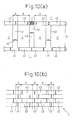
- FIGs. 10(a), 10(b) , 10(c), 10(d) and 10(e) show a typical oven wall brickwork structure.
- the structure uses three kinds of bricks: hammer brick 41 centered on an intersecting region 7 and extending across part of a stretcher brick wall 4 and part of a binder brick wall 5, stretcher brick 42 located in a stretcher brick wall 4, and binder brick 43 located in a binder brick wall 5.
- the hammer bricks 41 are arranged one every other binder brick wall. As shown in FIG. 10(b) , the hammer bricks 41 are staggered in the vertically stacked courses.
- each joint 44 includes a tongue in groove joint 45 that helps to increase the strength and improve the sealing property of the brickwork structure.
- the arrangement of the vertical joints is not continuous but offset every tier. The ordinary practice is to lay the bricks so that their coarse joints are continuous in the horizontal direction.
- joints are present in two vertical rows per flue.
- the vertical joints are not continuous. Instead, joints and stretcher bricks are arranged alternately in the vertical direction.
- cracks 51 occur in the stretcher bricks located between the joints of the facing regions, and joint gaps 52 form in the joints of the flue facing regions in contact with the cracks. Owing to the continuity of the brick cracks and the joint gaps, it frequently happens that, as shown in FIG.
- vertical through-cracks 53 form in the oven height direction of the stretcher brick walls.
- a coking chamber wall in which a vertical through-crack 53 has occurred comes under a vertical load, it may not be able to withstand the load and the cracked bricks in the stretcher brick wall may cave in.
- Japanese Patent Publication ( A) No. 2005-307003 ('003) teaches utilization of an angular U-shaped brick that faces the coking chamber and sandwiches the combustion chamber flue to structurally integrate a pair of binder brick walls and a stretcher brick wall in the oven longitudinal direction.
- the U-shaped brick is disposed at every other combustion chamber flue, neighboring U-shaped bricks are connected to a rectangular solid brick to form the stretcher brick wall of the oven.
- the stretcher brick wall has no joints, so that thermal cracks caused by joint gaps can be avoided.
- the binder brick walls and the stretcher brick walls are structurally integrated, the arrangement also exhibits an effect of offering extremely high rigidity with respect to side wall and locally concentrated load.
- the brickwork structure of '003 uses angularly U-shaped bricks to structurally unite the pair of binder brick walls and the stretcher brick wall and has a drawback in that the U-shaped brick is heavy. For easier handling during oven construction, it is generally required to keep the unit brick weight to 25 kg or less.
- the weight of the U-shaped brick taught by '003 can be held to within 25 kg by reducing the brick height to around 2/3 the ordinary size.
- use of bricks that are 2/3 the usual height would rather increase bricklaying labor because it would require the number of brick courses in the coking chamber height direction to be increased 1.5 times.
- the thinner brick profile would also cause other problems. For example, the bricks would be more susceptible to deformation during handling at the time of brickmaking and firing. The resulting impossibility of realizing a right-angled brick structure would make oven building difficult.
- the object of the present invention is to provide an oven wall brickwork structure for a chamber type coke oven including stretcher brick walls partitioning coking chambers and combustion chambers, and binder brick walls partitioning adjacent combustion chamber flues, which oven wall brickwork structure does not experience cave-in owing to vertical through-cracks in the stretcher brick wall and is easy to build.
- the gist of the invention is as set out below.
- the partitioning walls separating the coking chambers 1 and series of combustion chambers 2 are called “stretcher brick walls 4" and the partitioning walls separating the combustion chamber flues 3 from each other are called “binder brick walls 5.”
- the stretcher brick walls 4 can be further divided into portions where the flues 3 and the coking chambers 1 face one another (flue facing regions 6) and portions within regions 8 on extensions of the binder walls (intersecting regions 7).
- the coke oven wall brickwork structure requires stretcher A bricks 11 and stretcher B bricks 12.
- the stretcher A brick 11 is an L-shaped brick integrating part of the stretcher wall 4 and part of the binder brick wall 5.
- the stretcher A brick 11 includes an intersecting region 7, and further includes part of the stretcher wall in contact with one side of the intersecting region 7, and part of the binder wall in contact with the intersecting region 7.
- the L-shaped corner of the stretcher A brick 11 has, at the part thereof corresponding to the stretcher wall (corresponding to the intersecting region 7), a shoulder 14 for receiving a stretcher B brick 12.
- the stretcher wall portion end of the stretcher A brick 11 on the opposite side from the shoulder is hereinafter sometimes called the "stretcher end 15."
- the stretcher B brick 12 is a brick that forms part of the stretcher wall. As shown in FIG. 1(c) , its shape is substantially that of a rectangular solid (rectangular parallelepiped).
- first combustion chamber flues 3a and second combustion chamber flues 3b are arranged as shown in FIG. 1(a) .
- the first combustion chamber flues 3a and second combustion chamber flues 3b are alternately disposed in the series of combustion chambers arranged in parallel with the coking chambers.
- the stretcher wall separating the first combustion chamber flue 3a from the coking chamber 1 is formed by the stretcher ends 15 of two stretcher A bricks (11a, 11b) in contact with each other.
- the stretcher wall separating the second combustion chamber flue 3b from the coking chamber 1 is formed between opposing shoulders 14 of two stretcher A bricks (11a, 11c) by a stretcher B brick 12 whose opposite ends are received by the shoulders 14 of the two stretcher A bricks (11a, 11c).
- the shoulder 14 of the stretcher A brick 11 is formed in the intersecting region 7.
- the mating faces (joint 17) between the shoulder 14 of the stretcher A brick 11 and the end of the stretcher B brick 12 are situated in the intersecting region 7, i.e., in the stretcher wall within a region 8 on an extension of the binder wall.
- the series of combustion chambers are formed on both side with stretcher walls in contact the coking chambers. And both sides form brickwork structures composed of stretcher A bricks and stretcher B bricks in the foregoing manner.
- the binder brick wall 5 can be formed as shown in FIG. 2 by joining the binder wall ends of the stretcher A bricks 11 but it is also possible, as shown in FIGs. 1(a), 1(b), 1(c), 1(d) and 1(e) to interpose a separate binder brick 13 between the stretcher A bricks 11 on opposites sides. Provision of the separate binder brick 13 is preferable because it enables weight reduction of the individual stretcher A bricks.
- the binder wall is formed by two stretcher A bricks and a binder brick interposed between the two stretcher A bricks.
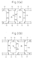
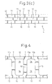
- FIGs. 3(a), 3(b) and 3(c) the first combustion chamber flues 3a and second combustion chamber flues 3b are interchanged relative to the foregoing presumption.
- a combustion chamber flue formed as a first combustion chamber flue 3a in the first course ( FIG. 3(a) ) by joining the stretcher ends of stretcher A bricks is in the second course ( FIG. 3(b) ) formed as a second combustion chamber flue 3b by installing a stretcher B brick.
- the brickwork structure separating the flues and the coking chambers is formed, as shown in FIG. 3(c) , by laying the bricks so that structures formed by contacting stretcher A bricks 11 with each other and structures formed by stretcher B bricks 12 alternate. The joints are therefore prevented from running continuously in the vertical direction.
- each L-shaped stretcher A brick 11 is connected at its stretcher end 15 to the adjacent stretcher A brick 11 and is also assembled into the associated binder brick wall 5.
- a load P acting perpendicularly to the stretcher end 15 from the coking chamber side can be borne solely by a single course of bricks without relying on the rigidity of an adjacent course or courses.
- Stretcher B bricks 12 of the adjacent courses make contact with joint region between the stretcher ends 15. Since the stretcher ends of the L-shaped stretcher A bricks 11 are joined together, a pressing load acting on the joint 16 between the stretcher ends produces a force in the direction of closing the joint 16.
- the vertical joints formed in the stretcher wall include not only the joints 16 between the stretcher ends 15 of the stretcher A bricks 11 but also the joints where the ends of the stretcher B bricks 12 and the shoulders 14 of the stretcher A bricks 11 meet (the joints 17). These latter joints are located in the intersecting regions 7, i.e., within regions 8 on extensions of the binder walls ( FIGs. 1(a), 1(b), 1(c), 1(d) and 1(e) ).
- the so-arranged joints are characterized in being resistant to formation of vertical through-cracks.
- the oven wall brickwork structure according to the present invention even if a vertical through-crack should form in a joint between the stretcher ends of stretcher A bricks 11 (a joint 16) (formed in a flue facing region 6), the crack cannot easily grow, so that the oven wall is safe from cave-in. Moreover, the probability of a vertical through-crack forming in the joint between a stretcher A brick 11 and a stretcher B brick 12 (joint 17) (formed in a intersecting region 7) is low from the start.
- the coke oven wall brickwork structure according to the invention can therefore prevent cave-in of bricks cracked as a result of vertical through-cracking.
- the dimensions of the stretcher wall formed where two stretcher A bricks 11 join at their stretcher ends will be explained with reference to FIG. 6 .
- the stretcher wall length La of the stretcher A brick 11a (distance from binder wall surface on the opposite side from the shoulder (binder surface S) to the outer extremity of stretcher end) can be the same as or different from the stretcher wall length Lb of the stretcher A brick 11b.
- the joint 16 between the stretcher ends is located at the stretcher wall center C.
- La and Lb are different, the joint is located apart from the center C.
- the joint 16 between the stretcher ends is located apart from the center C means that the stretcher wall length La is small and the stretcher wall length Lb is large, but when one or the other of the stretcher wall lengths is too long, the strength of the stretcher regions of the stretcher A bricks 11 declines.
- the length of the combustion chamber flue between the binder walls is defined as L 0
- the thickness of the stretcher region of the stretcher A brick 11 is defined as W (mm), the height of the stretcher A brick 11 as H (mm), the distance from the shoulder 14 of the stretcher A brick 11 to the surface of the binder wall on the opposite side from the shoulder (binder surface S) as B (mm), and the distance from the binder surface S to the stretcher end as stretcher length L.
- W mm
- H height of the stretcher A brick 11
- B the distance from the shoulder 14 of the stretcher A brick 11 to the surface of the binder wall on the opposite side from the shoulder (binder surface S) as B (mm)
- the distance from the binder surface S to the stretcher end as stretcher length L.
- P (kg) is the concentrated load acting on the joint between the stretcher ends of two stretcher A bricks and ⁇ b (kg/mm 2 ) is the allowable bending stress of the stretcher A brick.
- 2,000 kg is adopted as the concentrated load P.
- the brick can be further improved in strength by increasing P to the range of greater than 2,000 kg to 5,000 kg.
- Ordinary silica bricks have a ⁇ b of around 0.6 to 1.0 kg/mm 2 .
- the maximum tensile stress acts on the stretcher A brick in the vicinity of the stretcher root and the shoulder root. If the dimensions and shape of the stretcher A brick satisfy the left side of the Formulas ⁇ 1> and ⁇ 2>, the maximum tensile stress under the concentrated load can be kept within the allowable stress, occurrence of through-cracking can be inhibited, and the strength and rigidity of the stretcher A brick with respect to bending stress can be ensured. Moreover, by striking a good balance among the values of H, W and B, a well-balanced structure that minimizes brick unit weight can be established. Increasing brick height H while maintaining low weight makes it possible to reduce the number of courses, thereby improving brickwork constructability.
- brick processing (making) performance can be improved (no thermal deformation of thickness and height) to inhibit through-cracking (ensure required thickness), thereby enhancing safety through gas-leakage prevention and the like. It also becomes possible to establish the flue cross-sectional area needed for good heat transfer efficiency, and to improve brickwork constructability (reduce number of courses).
- the length L 0 of the flue between the binder walls of the combustion chamber is too small, combustion performance is degraded owing to insufficient space within the combustion chamber. If it is too large, the length of the stretcher wall increases to reduce stretcher brick rigidity, which in turn reduces the rigidity of the oven wall. These problems do not arise if the inter-binder wall length L 0 is in the range of 200 to 500 mm. If the thickness W of the stretcher region of the stretcher A brick is too small, the rigidity of the stretcher brick declines to lower the rigidity of the oven wall. If it is too large, heat transfer from the combustion chamber diminishes to lower coke oven efficiency.
- the thickness W of the stretcher region is in the range of 90 to 130 mm. If the height H of the stretcher A brick is too small, the number of brick courses in the coking chamber height direction must be increased, which increases the amount of bricklaying work. In addition, the thinner brick is more susceptible to deformation during handling at the time of brickmaking and firing. The resulting impossibility of realizing a right-angled brick structure is liable to make oven building difficult. If the height H is too large, brick handling is impeded by the increase in brick unit weight. These problems do not arise if the height H is in the range of 100 to 150 mm.
- the stretcher A brick of the invention is substantially L-shaped and includes a stretcher region facing the combustion chamber flue and a corner region that contacts the binder wall ( FIG. 7(a) ).
- the corner region 18 preferably has a curved region.
- the presence of the curved region mitigates stress concentration and increases rigidity against bending.
- the radius of curvature of the curved region is desirably equal to or greater than about 1/3 to 1/2 the thickness W of the stretcher brick (about 50 mm).
- the binder walls are sometimes equipped with ducts for passing air for multi-stage combustion conducted as an NOx countermeasure.
- this invention as shown in FIG. 8 , it is possible to provide through-holes 19 in the binder regions of the stretcher A bricks 11 or in the binder bricks 13 or in both and to form the binder wall ducts of the through-holes 19. This is preferable because the through-holes are can be used without modification as the ducts for multi-stage combustion.
- the coke oven wall brickwork structure uses stretcher A bricks to form joints in the stretcher brick wall.
- the stretcher A brick is formed to have an L-shape that straddles the stretcher wall and the binder wall, whereby it can withstand stress acting perpendicular to the stretcher brick wall. Even if a vertical through-crack should form along the stretcher wall joints, the bricks do not cave into the flue.
- brick unit weight can be reduce relative to that according to Japanese Patent Publication (A) No. 2005-307003 , so that the workload during construction can be kept low without need to reduce brick height.
Landscapes
- Chemical & Material Sciences (AREA)
- Engineering & Computer Science (AREA)
- Materials Engineering (AREA)
- Oil, Petroleum & Natural Gas (AREA)
- Organic Chemistry (AREA)
- Mechanical Engineering (AREA)
- General Engineering & Computer Science (AREA)
- Furnace Housings, Linings, Walls, And Ceilings (AREA)
Claims (7)
- Ziegelmauerwerkstruktur einer Koksofenwand, die Ziegel einer Läuferwand, die eine Wand ist, die eine Kokskammer und eine Brennkammer trennt, und Ziegel einer Binderwand umfasst, die eine Wand ist, die Brennkammer-Rauchabzugskanäle voneinander trennt, die aufweist
einen Läuferziegel A, der ein L-förmiger Ziegel ist, der integral einen Teil der Läuferwand und einen Teil der Binderwand kombiniert; und
einen Läuferziegel B, der ein Ziegel ist, der einen Teil der Läuferwand bildet;
wobei eine L-förmige Ecke des Läuferziegels A an einer Stelle davon, die der Läuferwand entspricht, mit einer Schulter ausgebildet ist, die zur Aufnahme des Läuferziegels B imstande ist, ein Läuferwandabschnittsende des Läuferziegels A auf der von der Schulter gegenüberliegenden Seite ein Läuferende bildet und ein Ineinandergreifen der Läuferenden von zwei Läuferziegeln A miteinander eine Läuferwand bildet, die einen ersten Brennkammer-Rauchabzugskanal und eine Kokskammer trennt, ein Läuferziegel B, der an seinen gegenüberliegenden Enden durch die Schultern von zwei Läuferziegeln A aufgenommen ist, die so angeordnet sind, dass ihre Schultern zueinander weisen, eine Läuferwand bildet, die einen zweiten Brennkammer-Rauchabzugskanal und die Kokskammer trennt, und der erste Brennkammer-Rauchabzugskanal und der zweite Brennkammer-Rauchabzugskanal abwechselnd angeordnet sind. - Ziegelmauerwerkstruktur einer Koksofenwand nach Anspruch 1, wobei die Binderwand durch zwei Läuferziegel A und einen Binderziegel gebildet wird, der zwischen den beiden Läuferziegeln A angeordnet ist.
- Ziegelmauerwerkstruktur einer Koksofenwand nach Anspruch 1 oder 2, wobei die Ziegelmauerwerkstruktur an der Läuferziegelwand, die den Brennkammer-Rauchabzugskanal und die Kokskammer trennt, durch abwechselndes Übereinanderlegen einer Struktur, die aus Läuferziegeln ausgebildet ist, die miteinander in Kontakt stehen, und einer Struktur gebildet wird, die aus einem Läuferziegel B gebildet wird.
- Ziegelmauerwerkstruktur einer Koksofenwand nach einem der Ansprüche 1 bis 3, wobei der Abstand zwischen Binderwänden eines Brennkammer-Rauchabzugskanals als L0 definiert ist und eine Verbindungsstelle zwischen den Läuferenden der Läuferziegel A innerhalb ± 0,05 L0 von der Mitte des Rauchabzugskanals liegt, und
wobei die folgenden Beziehungen erfüllt werden:

wobei W die Dicke des Läuferbereichs des Läuferziegels A ist, H die Höhe des Läuferziegels A ist, B der Abstand von der Schulter des Läuferziegels A zur Oberfläche der Binderwand auf der von der Schulter (Binderoberfläche S) gegenüberliegenden Seite ist, und L die Läuferlänge ist, die als der Abstand von der Binderoberfläche S zum Läuferende definiert ist,
unter der Voraussetzung, dass P die Punktlast ist, die auf die Verbindungsstelle zwischen den Läuferenden der Läuferziegel A wirkt, und einen Wert von 2000 kg bis 5000 kg aufweist, und σb die zulässige Biegespannung des Läuferziegels A ist. - Ziegelmauerwerkstruktur einer Koksofenwand nach einem der Ansprüche 1 bis 4, wobei die Länge L0 des Brennkammer-Rauchabzugskanals zwischen Binderwänden 200 bis 500 mm beträgt, die Dicke W des Läuferbereichs des Läuferziegels A 90 bis 130 mm beträgt, die Höhe H des Läuferziegels A 100 bis 150 mm beträgt und der Abstand B von der Schulter des Läuferziegels A zur Binderwandoberfläche auf der von der Schulter (Binderoberfläche S) gegenüberliegenden Seite 100 bis 250 mm beträgt.
- Ziegelmauerwerkstruktur einer Koksofenwand nach einem der Ansprüche 1 bis 5, wobei ein Eckbereich, wo sich der Läuferbereich des Läuferziegels A, der zum Brennkammer-Rauchabzugskanal weist, und die Binderziegelwand treffen, einen gekrümmten Bereich aufweist.
- Ziegelmauerwerkstruktur einer Koksofenwand nach einem der Ansprüche 1 bis 6, wobei der Binderbereich des Läuferziegels A und/oder der Binderziegel ein Durchgangsloch zum Bilden eines Kanals in der Binderwand aufweisen.
Applications Claiming Priority (2)
| Application Number | Priority Date | Filing Date | Title |
|---|---|---|---|
| JP2006314239A JP4926667B2 (ja) | 2006-11-21 | 2006-11-21 | コークス炉の炉壁煉瓦積み構造 |
| PCT/JP2007/072993 WO2008062899A1 (fr) | 2006-11-21 | 2007-11-21 | Structure en briquetage pour paroi de four à coke |
Publications (3)
| Publication Number | Publication Date |
|---|---|
| EP2085455A1 EP2085455A1 (de) | 2009-08-05 |
| EP2085455A4 EP2085455A4 (de) | 2014-04-30 |
| EP2085455B1 true EP2085455B1 (de) | 2015-01-14 |
Family
ID=39429826
Family Applications (1)
| Application Number | Title | Priority Date | Filing Date |
|---|---|---|---|
| EP07849909.2A Active EP2085455B1 (de) | 2006-11-21 | 2007-11-21 | Backsteinstruktur für eine koksofenwand |
Country Status (9)
| Country | Link |
|---|---|
| EP (1) | EP2085455B1 (de) |
| JP (1) | JP4926667B2 (de) |
| KR (1) | KR101066790B1 (de) |
| CN (1) | CN101535446B (de) |
| AU (1) | AU2007322602B2 (de) |
| BR (1) | BRPI0719022B1 (de) |
| RU (1) | RU2410408C1 (de) |
| TW (1) | TW200835782A (de) |
| WO (1) | WO2008062899A1 (de) |
Families Citing this family (4)
| Publication number | Priority date | Publication date | Assignee | Title |
|---|---|---|---|---|
| JP2010028049A (ja) * | 2008-07-24 | 2010-02-04 | Kyocera Corp | 発光装置及び照明装置 |
| US8266853B2 (en) * | 2009-05-12 | 2012-09-18 | Vanocur Refractories Llc | Corbel repairs of coke ovens |
| CN102452786A (zh) * | 2010-11-03 | 2012-05-16 | 中国中轻国际工程有限公司 | 玻璃熔窑的多层池壁接缝结构 |
| JP6524439B2 (ja) * | 2015-06-29 | 2019-06-05 | 日本製鉄株式会社 | コークス炉燃焼室用耐火物ブロックおよびコークス炉燃焼室の耐火物ブロック積み構造 |
Family Cites Families (7)
| Publication number | Priority date | Publication date | Assignee | Title |
|---|---|---|---|---|
| US1782638A (en) * | 1926-02-13 | 1930-11-25 | Totzek Fritz | Coke-oven-wall structure |
| SU11064A1 (ru) * | 1926-09-11 | 1929-09-30 | Карл Штилль | Устройство дл отоплени горизонтальных коксовальных печей с вертикальными нагревательными каналами |
| DE2416948B2 (de) * | 1974-04-08 | 1976-05-26 | Verfahren zum aufbau und zur reparatur einer kokskammerofenwand | |
| DE2430053C2 (de) * | 1974-06-22 | 1982-10-21 | Krupp-Koppers Gmbh, 4300 Essen | Heizwand für Horizontalkoksofenbatterien |
| DE4244547A1 (de) * | 1992-12-30 | 1994-07-07 | Lichtenberg Feuerfest | Formstein für die Zustellung von Koksofenkammern |
| JPH0987633A (ja) * | 1995-09-18 | 1997-03-31 | Sumitomo Metal Ind Ltd | コークス炉補修時の異物除去用開口の閉塞方法 |
| JP2005307003A (ja) * | 2004-04-21 | 2005-11-04 | Nippon Steel Corp | コークス炉炉壁の煉瓦積構造 |
-
2006
- 2006-11-21 JP JP2006314239A patent/JP4926667B2/ja active Active
-
2007
- 2007-11-21 TW TW96144077A patent/TW200835782A/zh unknown
- 2007-11-21 BR BRPI0719022A patent/BRPI0719022B1/pt active IP Right Grant
- 2007-11-21 EP EP07849909.2A patent/EP2085455B1/de active Active
- 2007-11-21 WO PCT/JP2007/072993 patent/WO2008062899A1/ja not_active Ceased
- 2007-11-21 KR KR1020097010276A patent/KR101066790B1/ko active Active
- 2007-11-21 CN CN200780041747XA patent/CN101535446B/zh active Active
- 2007-11-21 AU AU2007322602A patent/AU2007322602B2/en active Active
- 2007-11-21 RU RU2009123518/05A patent/RU2410408C1/ru active
Also Published As
| Publication number | Publication date |
|---|---|
| AU2007322602B2 (en) | 2010-09-02 |
| TWI376410B (de) | 2012-11-11 |
| RU2410408C1 (ru) | 2011-01-27 |
| EP2085455A1 (de) | 2009-08-05 |
| CN101535446A (zh) | 2009-09-16 |
| EP2085455A4 (de) | 2014-04-30 |
| TW200835782A (en) | 2008-09-01 |
| AU2007322602A1 (en) | 2008-05-29 |
| KR20090069196A (ko) | 2009-06-29 |
| JP4926667B2 (ja) | 2012-05-09 |
| WO2008062899A1 (fr) | 2008-05-29 |
| BRPI0719022B1 (pt) | 2018-10-30 |
| JP2008127472A (ja) | 2008-06-05 |
| BRPI0719022A2 (pt) | 2013-12-17 |
| CN101535446B (zh) | 2012-10-31 |
| KR101066790B1 (ko) | 2011-09-21 |
Similar Documents
| Publication | Publication Date | Title |
|---|---|---|
| KR100563900B1 (ko) | 금속 시트 파일 | |
| EP2085455B1 (de) | Backsteinstruktur für eine koksofenwand | |
| CN111630232B (zh) | 复合建筑板及壳 | |
| US2192642A (en) | Furnace construction | |
| JP2005307003A (ja) | コークス炉炉壁の煉瓦積構造 | |
| EA012996B1 (ru) | Многокамерная печь с усовершенствованными компенсационными температурными швами и кирпичи, предназначенные для реализации таких швов | |
| JP2020033402A (ja) | コークス炉構成用煉瓦およびコークス炉の煉瓦積み構造 | |
| US4842511A (en) | Carbon baking furnace--refractory construction | |
| JP4777034B2 (ja) | コークス炉炉壁の煉瓦積構造 | |
| JP5177169B2 (ja) | コークス炉炉壁の煉瓦積構造 | |
| CA1138736A (en) | Block or brick for the construction of a two-shell tile stove | |
| CN209246683U (zh) | 一种强固型石灰窑砌砖 | |
| JP7684552B2 (ja) | 室炉式コークス炉の燃焼室端部の煉瓦組積構造体 | |
| JP5491327B2 (ja) | 窯炉側壁の築炉構造 | |
| LU507835B1 (en) | Coke oven heating wall repair, replacement or construction | |
| CN223925413U (zh) | 一种带有隔热层的电炉用镁质耐火砖结构 | |
| US2142404A (en) | Interlocking brick structure | |
| CA1119400A (en) | Hot blast stove breast wall | |
| JP4975772B2 (ja) | コークス炉炉壁の煉瓦積構造 | |
| EP2628806B1 (de) | Rh-entgasungs-untergefäss | |
| RU2219343C1 (ru) | Профиль горячекатаный для крепи горных выработок | |
| CN211646774U (zh) | 狱墙伸缩缝构造 | |
| JP7214546B2 (ja) | 地中連続壁のせん断破壊防止構造 | |
| SU1765153A1 (ru) | Перекрытие коксовых печей | |
| US1725900A (en) | Wall construction |
Legal Events
| Date | Code | Title | Description |
|---|---|---|---|
| PUAI | Public reference made under article 153(3) epc to a published international application that has entered the european phase |
Free format text: ORIGINAL CODE: 0009012 |
|
| 17P | Request for examination filed |
Effective date: 20090610 |
|
| AK | Designated contracting states |
Kind code of ref document: A1 Designated state(s): AT BE BG CH CY CZ DE DK EE ES FI FR GB GR HU IE IS IT LI LT LU LV MC MT NL PL PT RO SE SI SK TR |
|
| DAX | Request for extension of the european patent (deleted) | ||
| RAP1 | Party data changed (applicant data changed or rights of an application transferred) |
Owner name: NIPPON STEEL & SUMITOMO METAL CORPORATION |
|
| A4 | Supplementary search report drawn up and despatched |
Effective date: 20140402 |
|
| RIC1 | Information provided on ipc code assigned before grant |
Ipc: C10B 29/02 20060101AFI20140327BHEP Ipc: F27D 1/04 20060101ALI20140327BHEP |
|
| GRAP | Despatch of communication of intention to grant a patent |
Free format text: ORIGINAL CODE: EPIDOSNIGR1 |
|
| INTG | Intention to grant announced |
Effective date: 20140724 |
|
| GRAS | Grant fee paid |
Free format text: ORIGINAL CODE: EPIDOSNIGR3 |
|
| GRAA | (expected) grant |
Free format text: ORIGINAL CODE: 0009210 |
|
| AK | Designated contracting states |
Kind code of ref document: B1 Designated state(s): AT BE BG CH CY CZ DE DK EE ES FI FR GB GR HU IE IS IT LI LT LU LV MC MT NL PL PT RO SE SI SK TR |
|
| REG | Reference to a national code |
Ref country code: GB Ref legal event code: FG4D |
|
| REG | Reference to a national code |
Ref country code: CH Ref legal event code: EP |
|
| REG | Reference to a national code |
Ref country code: IE Ref legal event code: FG4D |
|
| REG | Reference to a national code |
Ref country code: AT Ref legal event code: REF Ref document number: 707066 Country of ref document: AT Kind code of ref document: T Effective date: 20150215 |
|
| REG | Reference to a national code |
Ref country code: DE Ref legal event code: R096 Ref document number: 602007040079 Country of ref document: DE Effective date: 20150226 |
|
| REG | Reference to a national code |
Ref country code: NL Ref legal event code: VDEP Effective date: 20150114 |
|
| REG | Reference to a national code |
Ref country code: AT Ref legal event code: MK05 Ref document number: 707066 Country of ref document: AT Kind code of ref document: T Effective date: 20150114 |
|
| REG | Reference to a national code |
Ref country code: LT Ref legal event code: MG4D |
|
| PG25 | Lapsed in a contracting state [announced via postgrant information from national office to epo] |
Ref country code: ES Free format text: LAPSE BECAUSE OF FAILURE TO SUBMIT A TRANSLATION OF THE DESCRIPTION OR TO PAY THE FEE WITHIN THE PRESCRIBED TIME-LIMIT Effective date: 20150114 Ref country code: BG Free format text: LAPSE BECAUSE OF FAILURE TO SUBMIT A TRANSLATION OF THE DESCRIPTION OR TO PAY THE FEE WITHIN THE PRESCRIBED TIME-LIMIT Effective date: 20150414 Ref country code: LT Free format text: LAPSE BECAUSE OF FAILURE TO SUBMIT A TRANSLATION OF THE DESCRIPTION OR TO PAY THE FEE WITHIN THE PRESCRIBED TIME-LIMIT Effective date: 20150114 Ref country code: FI Free format text: LAPSE BECAUSE OF FAILURE TO SUBMIT A TRANSLATION OF THE DESCRIPTION OR TO PAY THE FEE WITHIN THE PRESCRIBED TIME-LIMIT Effective date: 20150114 Ref country code: SE Free format text: LAPSE BECAUSE OF FAILURE TO SUBMIT A TRANSLATION OF THE DESCRIPTION OR TO PAY THE FEE WITHIN THE PRESCRIBED TIME-LIMIT Effective date: 20150114 |
|
| PG25 | Lapsed in a contracting state [announced via postgrant information from national office to epo] |
Ref country code: AT Free format text: LAPSE BECAUSE OF FAILURE TO SUBMIT A TRANSLATION OF THE DESCRIPTION OR TO PAY THE FEE WITHIN THE PRESCRIBED TIME-LIMIT Effective date: 20150114 Ref country code: PL Free format text: LAPSE BECAUSE OF FAILURE TO SUBMIT A TRANSLATION OF THE DESCRIPTION OR TO PAY THE FEE WITHIN THE PRESCRIBED TIME-LIMIT Effective date: 20150114 Ref country code: LV Free format text: LAPSE BECAUSE OF FAILURE TO SUBMIT A TRANSLATION OF THE DESCRIPTION OR TO PAY THE FEE WITHIN THE PRESCRIBED TIME-LIMIT Effective date: 20150114 Ref country code: GR Free format text: LAPSE BECAUSE OF FAILURE TO SUBMIT A TRANSLATION OF THE DESCRIPTION OR TO PAY THE FEE WITHIN THE PRESCRIBED TIME-LIMIT Effective date: 20150415 Ref country code: NL Free format text: LAPSE BECAUSE OF FAILURE TO SUBMIT A TRANSLATION OF THE DESCRIPTION OR TO PAY THE FEE WITHIN THE PRESCRIBED TIME-LIMIT Effective date: 20150114 Ref country code: IS Free format text: LAPSE BECAUSE OF FAILURE TO SUBMIT A TRANSLATION OF THE DESCRIPTION OR TO PAY THE FEE WITHIN THE PRESCRIBED TIME-LIMIT Effective date: 20150514 |
|
| REG | Reference to a national code |
Ref country code: DE Ref legal event code: R097 Ref document number: 602007040079 Country of ref document: DE |
|
| PG25 | Lapsed in a contracting state [announced via postgrant information from national office to epo] |
Ref country code: SK Free format text: LAPSE BECAUSE OF FAILURE TO SUBMIT A TRANSLATION OF THE DESCRIPTION OR TO PAY THE FEE WITHIN THE PRESCRIBED TIME-LIMIT Effective date: 20150114 Ref country code: EE Free format text: LAPSE BECAUSE OF FAILURE TO SUBMIT A TRANSLATION OF THE DESCRIPTION OR TO PAY THE FEE WITHIN THE PRESCRIBED TIME-LIMIT Effective date: 20150114 Ref country code: RO Free format text: LAPSE BECAUSE OF FAILURE TO SUBMIT A TRANSLATION OF THE DESCRIPTION OR TO PAY THE FEE WITHIN THE PRESCRIBED TIME-LIMIT Effective date: 20150114 Ref country code: DK Free format text: LAPSE BECAUSE OF FAILURE TO SUBMIT A TRANSLATION OF THE DESCRIPTION OR TO PAY THE FEE WITHIN THE PRESCRIBED TIME-LIMIT Effective date: 20150114 Ref country code: CZ Free format text: LAPSE BECAUSE OF FAILURE TO SUBMIT A TRANSLATION OF THE DESCRIPTION OR TO PAY THE FEE WITHIN THE PRESCRIBED TIME-LIMIT Effective date: 20150114 |
|
| PLBE | No opposition filed within time limit |
Free format text: ORIGINAL CODE: 0009261 |
|
| STAA | Information on the status of an ep patent application or granted ep patent |
Free format text: STATUS: NO OPPOSITION FILED WITHIN TIME LIMIT |
|
| 26N | No opposition filed |
Effective date: 20151015 |
|
| PG25 | Lapsed in a contracting state [announced via postgrant information from national office to epo] |
Ref country code: SI Free format text: LAPSE BECAUSE OF FAILURE TO SUBMIT A TRANSLATION OF THE DESCRIPTION OR TO PAY THE FEE WITHIN THE PRESCRIBED TIME-LIMIT Effective date: 20150114 |
|
| PG25 | Lapsed in a contracting state [announced via postgrant information from national office to epo] |
Ref country code: BE Free format text: LAPSE BECAUSE OF FAILURE TO SUBMIT A TRANSLATION OF THE DESCRIPTION OR TO PAY THE FEE WITHIN THE PRESCRIBED TIME-LIMIT Effective date: 20150114 |
|
| PG25 | Lapsed in a contracting state [announced via postgrant information from national office to epo] |
Ref country code: MC Free format text: LAPSE BECAUSE OF FAILURE TO SUBMIT A TRANSLATION OF THE DESCRIPTION OR TO PAY THE FEE WITHIN THE PRESCRIBED TIME-LIMIT Effective date: 20150114 Ref country code: LU Free format text: LAPSE BECAUSE OF FAILURE TO SUBMIT A TRANSLATION OF THE DESCRIPTION OR TO PAY THE FEE WITHIN THE PRESCRIBED TIME-LIMIT Effective date: 20151121 |
|
| REG | Reference to a national code |
Ref country code: CH Ref legal event code: PL |
|
| GBPC | Gb: european patent ceased through non-payment of renewal fee |
Effective date: 20151121 |
|
| PG25 | Lapsed in a contracting state [announced via postgrant information from national office to epo] |
Ref country code: CH Free format text: LAPSE BECAUSE OF NON-PAYMENT OF DUE FEES Effective date: 20151130 Ref country code: LI Free format text: LAPSE BECAUSE OF NON-PAYMENT OF DUE FEES Effective date: 20151130 |
|
| REG | Reference to a national code |
Ref country code: IE Ref legal event code: MM4A |
|
| REG | Reference to a national code |
Ref country code: FR Ref legal event code: ST Effective date: 20160729 |
|
| PG25 | Lapsed in a contracting state [announced via postgrant information from national office to epo] |
Ref country code: GB Free format text: LAPSE BECAUSE OF NON-PAYMENT OF DUE FEES Effective date: 20151121 Ref country code: IE Free format text: LAPSE BECAUSE OF NON-PAYMENT OF DUE FEES Effective date: 20151121 |
|
| PG25 | Lapsed in a contracting state [announced via postgrant information from national office to epo] |
Ref country code: FR Free format text: LAPSE BECAUSE OF NON-PAYMENT OF DUE FEES Effective date: 20151130 |
|
| PG25 | Lapsed in a contracting state [announced via postgrant information from national office to epo] |
Ref country code: HU Free format text: LAPSE BECAUSE OF FAILURE TO SUBMIT A TRANSLATION OF THE DESCRIPTION OR TO PAY THE FEE WITHIN THE PRESCRIBED TIME-LIMIT; INVALID AB INITIO Effective date: 20071121 |
|
| PG25 | Lapsed in a contracting state [announced via postgrant information from national office to epo] |
Ref country code: CY Free format text: LAPSE BECAUSE OF FAILURE TO SUBMIT A TRANSLATION OF THE DESCRIPTION OR TO PAY THE FEE WITHIN THE PRESCRIBED TIME-LIMIT Effective date: 20150114 |
|
| PG25 | Lapsed in a contracting state [announced via postgrant information from national office to epo] |
Ref country code: MT Free format text: LAPSE BECAUSE OF FAILURE TO SUBMIT A TRANSLATION OF THE DESCRIPTION OR TO PAY THE FEE WITHIN THE PRESCRIBED TIME-LIMIT Effective date: 20150114 Ref country code: TR Free format text: LAPSE BECAUSE OF FAILURE TO SUBMIT A TRANSLATION OF THE DESCRIPTION OR TO PAY THE FEE WITHIN THE PRESCRIBED TIME-LIMIT Effective date: 20150114 |
|
| PG25 | Lapsed in a contracting state [announced via postgrant information from national office to epo] |
Ref country code: PT Free format text: LAPSE BECAUSE OF FAILURE TO SUBMIT A TRANSLATION OF THE DESCRIPTION OR TO PAY THE FEE WITHIN THE PRESCRIBED TIME-LIMIT Effective date: 20150114 |
|
| REG | Reference to a national code |
Ref country code: DE Ref legal event code: R082 Ref document number: 602007040079 Country of ref document: DE Representative=s name: VOSSIUS & PARTNER PATENTANWAELTE RECHTSANWAELT, DE Ref country code: DE Ref legal event code: R081 Ref document number: 602007040079 Country of ref document: DE Owner name: NIPPON STEEL CORPORATION, JP Free format text: FORMER OWNER: NIPPON STEEL & SUMITOMO METAL CORP., TOKYO, JP |
|
| PGFP | Annual fee paid to national office [announced via postgrant information from national office to epo] |
Ref country code: DE Payment date: 20241001 Year of fee payment: 18 |
|
| PGFP | Annual fee paid to national office [announced via postgrant information from national office to epo] |
Ref country code: IT Payment date: 20241010 Year of fee payment: 18 |