EP2085509A2 - Procédé de mesure et de contrôle du niveau de puce de récipient de digestion ou d'imprégnation au moyen de la mesure de la pression de puce - Google Patents
Procédé de mesure et de contrôle du niveau de puce de récipient de digestion ou d'imprégnation au moyen de la mesure de la pression de puce Download PDFInfo
- Publication number
- EP2085509A2 EP2085509A2 EP08011872A EP08011872A EP2085509A2 EP 2085509 A2 EP2085509 A2 EP 2085509A2 EP 08011872 A EP08011872 A EP 08011872A EP 08011872 A EP08011872 A EP 08011872A EP 2085509 A2 EP2085509 A2 EP 2085509A2
- Authority
- EP
- European Patent Office
- Prior art keywords
- pressure
- chip
- vessel
- liquor
- level
- Prior art date
- Legal status (The legal status is an assumption and is not a legal conclusion. Google has not performed a legal analysis and makes no representation as to the accuracy of the status listed.)
- Withdrawn
Links
Images


Classifications
-
- D—TEXTILES; PAPER
- D21—PAPER-MAKING; PRODUCTION OF CELLULOSE
- D21C—PRODUCTION OF CELLULOSE BY REMOVING NON-CELLULOSE SUBSTANCES FROM CELLULOSE-CONTAINING MATERIALS; REGENERATION OF PULPING LIQUORS; APPARATUS THEREFOR
- D21C7/00—Digesters
- D21C7/12—Devices for regulating or controlling
-
- D—TEXTILES; PAPER
- D21—PAPER-MAKING; PRODUCTION OF CELLULOSE
- D21B—FIBROUS RAW MATERIALS OR THEIR MECHANICAL TREATMENT
- D21B1/00—Fibrous raw materials or their mechanical treatment
Definitions
- This invention relates generally to chemical treatment of lignocellulosic fibrous material in pulp production and, particularly, to automatic sensing and control systems in a chemical digester or impregnation vessel processing the fibrous material.
- Lignocellulosic material such as wood chips
- a digester or impregnation vessel Heat, pressure and liquor are also introduced to the vessel to process the material.
- the processing of wood chips may be continuous as chips are introduced to the top of the vessel while processed chips are discharged from the bottom of the vessel.
- the level of wood chips in the vessel is monitored to ensure that an appropriate amount of chips are in the vessel and that the chips are retained in the vessel for an appropriate period of time. Accurate information regarding the chip level is needed to properly regulate the flow of chips to the top of the vessel, the discharge of chips from the bottom of the vessel, and the pressure of the chips in the vessel.
- the chip level is conventionally measured by strain gauge sensors on paddles extending into the digester or impregnation vessel. Typically three or four paddles are arranged in a digester vessel. Each paddle includes strain gauge sensors that measure the forces applied by the moving chip column in the vessel to the paddles. The strain gauge sensors generate voltage signals indicative of the forces applied by the chip column to the paddle. The signals generated by the strain gauges are used to calculate a chip level in the vessel and for controlling the chip processing in the vessel.
- the strain gauges require paddles that extend into the chip flow and, thus, partially obstruct the flow.
- the strain gauges provide valid data when there is a chip flow and tend not to provide valid data when the chips are stationary in the vessel.
- the data generated by the strain gauges is highly sensitive to the chip flow rate through the vessel which may not be a constant rate.
- a novel system and method has been developed to determine the chip level in a vessel, e.g., a digester and impregnation vessel, based on chip pressure in the vessel.
- the novel system includes determining the chip pressure based on a differential of the total slurry pressure in the vessel and the hydrostatic pressure due to the liquor component of the slurry.
- a pressure sensing element has been developed for a vessel containing a slurry of lignocellulosic chip material, the element including: a first pressure sensing surface in contact with the slurry, wherein the first pressure sensing surface generates a signal representative of total static pressure of the slurry; a second pressure sensing surface generating a signal representative of a hydrostatic pressure of liquor in the slurry, and a pressure difference transmitter receiving the signals generated by the first and second pressure sensing surfaces and outputting a signal indicative of the chip pressure.
- a filter such as a screen, perforated plate, mesh or other device in front of the second pressure sensing surface may block chips and pass liquor to the second pressure sensing surface.
- a method for determining a pressure of the chips in a vessel containing a slurry of lignocellulosic material comprising: sensing a total pressure of the slurry in the vessel; sensing a hydrostatic pressure of the liquor in the vessel, and determining the pressure of the chips based on a difference of the sensed total pressure of the slurry and the sensed hydrostatic pressure of the liquor.
- a method has been developed to calibrate an algorithm to determine chip level comprising: measuring the liquor level in a vessel; measuring a chip pressure in the vessel; determining a calculated chip level using an algorithm to calculate the chip level based on the chip pressure; while varying the liquor level in the vessel, detecting a transition between a steady state chip pressure and a varying chip pressure; determining a difference existing at the transition between the liquor level and the calculated chip level; and adjusting the algorithm to compensate for the difference.
- a method for processing lignocellulosic chip material in a continuous flow vessel comprising: determining a chip pressure of the chip material based on a difference of a sensed total pressure of the slurry and a sensed pressure of the liquor; comparing the determined chip pressure of the chip material to a predetermined desired chip pressure; and adjusting a flow rate of the chip material through the vessel based on the comparison of the determined chip pressure to the predetermined desired chip pressure.
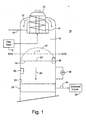
- FIGURE 1 is a schematic diagram of a treatment vessel for lignocellulosic fibrous material.
- FIGURE 2 is a schematic diagram of a front view of a pressure sensing element.
- FIGURE 3 is a schematic diagram of a cross-sectional view of the pressure sensing element.
- FIGURE 4 is a is a chart showing levels of chips and liquor in a vessel and chip pressure during a calibration process for an algorithm determining chip level.
- FIGURE 1 is a schematic diagram of a treatment vessel 10 for lignocellulosic fibrous material (referred to herein as "wood chips” or simply “chips").
- the vessel 10 may be, for example, a digesting vessel in a pulping system, or may be one of two or more vessels, where one vessel is a digesting vessel and the other vessel is an impregnation vessel.
- Chemical digesters and impregnation vessels are typically used to convert wood chips into a cellulose pulp from which paper products may be made. These vessels apply pressure, heat and cooking liquor to the chips.
- the digester and impregnation vessels are generally vertical columns often having heights greater than about 30 meters (100 feet).
- the vessels may be used in continuous flow processes, in which a slurry of wood chips and liquor is continually introduced and discharged to and from the vessel.
- the vessel may be used in batch processes wherein a slurry is sequentially introduced to the vessel, processed and discharged.
- a conventional chip feed system 12 provides a generally continuous flow of woods chips to a top separator 14 at the top of the vessel 10.
- the feed system mixes the chips with white liquor to form a slurry that flows to the top separator 14.
- the chips are discharged 13 from the top (or bottom) of the separator and a portion of the liquor is extracted 15 from the separator and vessel.
- the vessel may be a vapor-phase digester or a hydraulic digester.
- a hydraulic vessel is typically filled completely with cooking liquor to the top of the vessel 14.
- a vapor phase vessel typically has an upper gas filled region 16 above the upper level chips and liquor in the vessel.
- the chips form an upper surface 17 that is generally referred to as the chip level of the vessel.
- the chip level may be at, above or below the liquor level 18 in a vapor phase vessel.
- the chip level is typically below the liquor level, which fills the vessel during normal chip processing operations.
- the chip level 17 may be generally horizontal and may have an upper concave surface.
- An average elevation of the chip level is designated as L 1 .
- the chips With the chip level 17 and the liquor level 18 (which is designated as L 2 ), the chips compact under the hydrostatic pressure of the liquor and the weight of the chip column in the vessel. In a continuous flow vessel, the chips migrate downward from the chip level 17 towards the bottom of the vessel.
- liquor extraction screens 22 may be arranged on the sidewall 24 of the vessel. A portion 25 of the liquor in the vessel is extracted through the screens 22 and, at least temporarily, removed from the vessel. The treated wood chips are discharged from the bottom of the vessel 10 for further treatment.
- a pressure sensing element 26 is placed inside the vessel or on the vessel sidewall 24.
- the pressure sensing element is positioned above the uppermost extraction screens 22 and below the lowermost level of the chips during normal continuous flow operation of the vessel.
- the pressure sensing element 26 provides data regarding the pressures in the vessel and particularly the total pressure of the slurry in the vessel, the hydrostatic pressure of the liquor in the slurry, and indirectly the pressure attributable to the chips in the slurry.
- the measured chip pressure is used to determine a calculated chip level 17 in the vessel, where the calculated chip level L 1 is an average level of the upper chip surface 17.
- the total static pressure in the vessel is the sum of the hydrostatic pressure the liquor and the weight of the chip column above that elevation (referred to herein as the "static chip pressure” or just “chip pressure”).
- the chip pressure indicates the amount of chip compaction in the vessel at the elevation in the vessel at which the pressure is determined.
- the total static pressure of the slurry may be determined as the static pressure applied by the slurry to a unit area at a given depth in the vessel. In a hydraulic or vapor phase vessel, the total static pressure should vary in direct proportion to the depth of the slurry. Similarly, the static chip pressure should vary in direct proportion to the distance between the chip level and the elevation at which the static pressure is measured.
- the upper level of the chips in a vessel can be determined from a pressure measurement and the elevation in the vessel at which the pressure is measured.
- the chip level determination may be influenced by the liquor level in the vessel and, thus, measuring the liquor level may be useful in determining chip level.
- the total static pressure of the slurry is the combination of the hydrostatic pressure of the liquor and the static chip pressure.
- the hydrostatic pressure of the liquor is much larger than the static chip pressure and, thus, the hydrostatic pressure of the liquor is only slightly smaller than the total static pressure of the slurry.
- the pressure element 26 directly measures the large values of the hydrostatic pressure of the liquor and the static pressure of the slurry. The difference between the total static pressure of the slurry and the hydrostatic pressure of the liquor is used to determine the static chip pressure.
- FIGURES 2 and 3 are schematic diagrams of a front view and cross-sectional view of the pressure sensing element 26.
- the pressure sensing element 26 includes a first pressure sensor surface 28 in direct contact with the slurry of wood chips and liquor, and a second pressure sensor surface 30 in direct contact with only the liquor and not the chips.
- the pressure sensor surfaces 28, 30 may be each a diaphragm.
- a filter 32 such as a screen used in the extraction screen, perforated plate, mesh or porous disc, may shield the second pressure sensor surface 30 from the chip flow and allow liquor to flow through to the surface 30.
- the first and second pressure sensing surfaces may be attached to an inside surface of the sidewall 24 of the vessel or to a portal in the sidewall of the vessel.
- the pressure sensing element 26 may include a substrate or housing mounted in or to the vessel wall and that supports the first and second pressure sensor surfaces 28, 30.
- the pressure sensor surfaces 28, 30 may be each be mounted in an aperture 34 in the sidewall 24 of the vessel.
- a cylinder 36 mounted in the vessel wall or the substrate of the pressure sensing element may support the filter 32 and provide a chamber for the fluid pressing against the second pressure sensor surface 30.
- the first and second pressure sensor surfaces 28, 30, are preferably near each other and part of the same pressure sensing element 26.
- the pressure sensing element may be one of many types of sensors commonly used to measure liquid level in the tank or vessel. Depending on its function, the pressure sensing element may not require a filter to block the flow of chips.
- the chip filter 32 may be a screen, perforated plate, mesh, honeycombed plate or other device that blocks the flow of chips and allows passage of the liquor to the pressure sensor surface 30.
- the openings, e.g., apertures, slots or passages, in the filter are sufficiently narrow to block chips. Liquor passes through the filter and applies pressure to the second pressure sensor surface 30.
- the two pressure sensing surfaces 28, 30 are preferably at the same elevation, e.g., height, in the vessel to ensure equal liquor hydrostatic pressure on both sensing surfaces.
- the pressure sensing surfaces may be at an elevation in the vessel five to ten meters below the normal chip level.
- the sensing element surfaces are also preferably installed above the uppermost extraction screens 22 in the vessel.
- the exact installation location in a vessel, distance between the sensors and the manner of installation of the sensing surfaces 28, 30 and their associated pressure element 26 is a matter of design choice and may be defined by the design and construction of the digester or impregnation vessel and type of the digester. For example, if one of the pressure sensing surfaces is installed in an aperture in the sidewall of the vessel, the horizontal distance between the surface 30 in the aperture and the surface 28 on the sidewall may be greater than if the two surfaces 28, 30 are mounted on the sidewall.
- the sensing elements 26 may be installed on the inside wall 24 of the vessel or on the digester wall, or alternatively inside the vessel such as on an outside wall of a center pipe in the vessel or on a post extending from the outside wall 24 to inside the vessel. Further, the pressure sensing elements 26 should be installed so that the velocity and momentum of the chips have a minimal affect to the measured pressure signal.
- the sensor surfaces 28, 30 should preferably be arranged at an angle between parallel to the direction of the chip flow, e.g., the chip velocity vector (see slurry flow direction arrow 20) or 10 degrees inclined to the chip velocity vector (see arrow 20).
- each of the pressure sensing surfaces 28, 30, and particularly the surface 28 that is in contact with wood chips should preferably be relatively large, such as within twenty percent of 0.1 meters squared (m 2 ).
- the large surface area of the surface of the pressure sensing surface 28 provides sufficient contact area to sense the chips that tend to contact the surface at various angles, have different chip shapes and sizes, and may be more or less dense in the slurry in the vessel.
- the surface areas of the pressure sensing surfaces 28 and 30 may be different. For example, the surface of sensing surface 30 that is not in contact with chips may have a smaller area than the surface of sensing element 28 that is in contact with the chips. If the surface areas of the pressure sensing surfaces 28, 30 are different, the electronics of the pressure sensor are set up to account for the surface areas of the sensing elements and to determine the pressure given the area of the surfaces.
- the relatively large surface area, e.g., 0.1 m 2 , of the sensing surfaces 28, 30 minimizes the effect of variations in these parameters. Accordingly, large surface area sensing surfaces minimize undesirable influences on the signals generated by the surfaces that could degrade the accuracy of the pressure measurements.
- the parameters of contact angle, chip shape, and the density of chips may vary with time during the process in the vessel.
- the second pressure sensor surface 30 measures the hydrostatic pressure of the liquor.
- the second pressure sensor surface 30 does not measure the pressure of the chips, because the sensor surface 30 is behind a chip filter 32 and is shielded from the chips.
- the static pressure due to the chips is determined from the difference between the measurements of the hydrostatic liquor pressure sensed by pressure sensor surface 30 and the total static pressure made by pressure sensor surface 28.
- the pressure sensing element 26 may includes a DP sensor 35 having as inputs capillary pressure tubes 36, 38 that are hydraulically coupled to the pressure sensing surfaces 28, 30.
- the DP sensor measures the static pressure in both tubes 36, 38 and outputs a signal representative of the difference between the pressures in the capillary tubes.
- the tubes are each connected to a small fluid cavity 40 behind a respective one of the pressure sensing surfaces.
- the fluid filled cavities 40 serve as pressure repeaters to communicate the pressure applied to the surfaces 28, 30 to the capillary tubes.
- the surface deflects and applies a pressure in the cavity 40 and the capillary tube 36 that corresponds to the total static pressure of the slurry.
- the pressure in the cavity 40 and the capillary tube 38 is representative of the hydrostatic pressure of the liquor on the opposite side of the diaphragm.
- the liquor may be highly alkaline and at a high temperature.
- the pressure sensing surfaces 28, 30 serve as pressure repeaters transferring the pressure of the slurry and the liquor to the hydraulic liquid in the capillary tubes.
- the diaphragm surfaces 28, 30 allow the pressure of the slurry and liquor to be applied to the DP sensor 35 without exposing the sensor to the alkaline and temperatures of the liquor.
- a liquor density sensor 44 ( Fig. 1 ) to measure the liquor density (R2).
- the liquor density may be measured by using a pressure difference based sensor 45. Knowing the liquor density allows for compensations to be made in the determination of chip pressure if the liquor density changes during the processing of the chips in the vessel.
- a liquor level sensor 38 may be used to determine the liquor level 18 in the vessel. The liquor level may be used in the calculation to determine the chip level from chip pressure.
- Chip pressure affects chip compaction in the vessel.
- the chip pressure at each elevation in the vessel is an indicator of the compaction of the chips in the vessel at that elevation and lower elevations in the vessel.
- a profile of chip compaction over the entire digester length can be prepared based on the chip pressure as measured at various elevations in the vessel.
- the compaction profile can be used, for example, to determine the chip retention period in the vessel and at various zones in the vessel. For example, the compaction profile may be used to determine the retention time of chips in a cooking zone of a digester vessel.
- Chip pressure can be used to control the vessel, e.g., the flow of chips into and out of the vessel, to better stabilize the chip compaction profile in the vessel and thereby minimize variations in the quality of the processed chips discharged from the vessel.
- the chip pressure measurement provides data helpful to stabilize the impregnation or cooking processes in the vessel.
- the chip pressure data may be used by a controller for the vessel to adjust the control parameters for the vessel, e.g., flow rates of chip input and discharge to the vessel, to maintain a constant chip pressure at selected elevations in the vessel.
- a computer controller 42 may monitor the chip pressure signal output from the pressure sensing element and compare the measured chip pressure to a desired chip pressure. If the difference between the measured chip pressure and the desired chip pressure exceeds a predetermined range, e.g., within ten percent of the desired chip pressure, the controller may adjust the slurry flow rate into the top separate or the chip discharge rate from the bottom of the vessel to reduce the difference.
- the pressure sensing elements 26 may be used to monitor chip level in the vessel and control the chip pressure in the vessel. Using the data from the pressure sensing elements, an operator or an automatic control system 46 may, for example, select to control the chip level in the vessel or to control the chip pressure in the vessel. The control system may regulate the slurry flow into the vessel or discharge rate of processed chips from the vessel. If the controller 42 is in a mode to maintain the chip level within a predetermine range of elevations in the vessel, the controller may calculate the chip level based on the chip pressure and, if the calculated chip level is outside of an acceptable range of elevations, increase or reduce the slurry flow into the top separator or the chip discharge rate from the bottom of the vessel to raise or lower the chip level to the acceptable range.
- the controller 42 may compare the measured chip pressure to a range of acceptable limits for the chip pressure in the vessel and adjust the flow of chips into or out of the vessel to keep the chip pressure within these limits.
- the control system may maintain a constant chip pressure in the vessel provided that the chip level does not exceed a predetermined range of elevations in the vessel. By keeping a constant chip pressure, chip density variations can be minimized in the chip compaction profile for the vessel. Further, controlling the chip pressure in a vessel (rather than directly controlling the chip level) may be helpful in reducing the kappa number variation by compensating for the effects of chip density and air content variations and disturbances.
- the chip pressure is a function of the height of the chip column above the sensing element 26, the height of the liquor column in the vessel above the sensing element, liquor density and chip density in the vessel.
- An algorithm for determining chip pressure (PC) for a range of chip levels (L1) and liquor levels (L2) above the sensor element 22 is as follows:
- PC chip pressure (Pa - atmospheric pressure);
- L1 is the average chip level in the vessel [meters (m)];
- L2 is the liquor level in the vessel [m];
- R1 is the density of chips entrained by liquor in the vessel [kg/m 3 ];
- R2 is the density of free liquor [kg/m 3 ], and
- G is the gravitational force constant [kg/(ms 2 )].
- min ⁇ L1; L2 ⁇ indicates a selection of the smaller value of L1 and L2.
- max ⁇ L1-L2; 0 ⁇ indicates a selection of a positive value of the difference between L1 and L2 or a selection of zero if the difference is a negative value.
- the Solution 1 formula is selected if the liquor level is above the chip level and the Solution 2 formula is selected if the chip level is above the liquor level.
- a determination may be made using both the Solution 1 and 2 formulas, and the checking if the pre-condition for L1 and L2 relationship is valid.
- the result obtained by the valid formula (Solution 1 or 2) is then selected as the correct chip level estimate L1.
- a measured liquor density R2 from sensor 44 or 45 may be used to estimate of the density of liquor impregnated wood chips (R1) using the following formula:
- R ⁇ 1 Eps * RW + 1 - Eps * R ⁇ 2
- EPS and RW are wood type specific parameters; Eps is the volume fraction of solid wood material in a porous wood chip; (1-Eps) is the volume fraction of liquor in a porous wood chip, and RW is solid wood density.
- Eps may be in a range of 0.6 to 0.75, and RW may be in a range of 1300 kg/m 3 to 1650 kg/m3. It is assumed that wood chips are fully penetrated by liquor and no air remains inside wood chip.
- FIGURE 4 is a chart 50 illustrating a chip level calibration technique.
- the horizontal axis represents time (nos. 1 to 39) in the operation of the vessel.
- the vertical axis 52 on the left hand side of the chart represents the height of the vessel, where the vessel is approximately 12 meters high.
- the vertical axis 54 on the right hand side of the chart represents static pressure of the chips within the vessel in kilo (1,000) of Pascal (Newtons per square meter).
- the chip level calculated based on the data from the pressure sensing element 26 may be calibrated using the liquor level data collected by liquor level sensor 38 (see Fig. 1 ).
- the liquor level data is directly measured by the liquor level sensor and is treated as being accurate and suitable for use as a reference value for purposes of calibrating the chip level determination.
- the calibration process varies the amount of liquor in the vessel such that the liquor level (line 58 in chart 4) rises above and then falls below the actual chip level.
- the actual chip level is preferably held constant during the calibration process.
- the chip level is determined (line 56) based on the chip pressure (line 60) using the algorithms described above.
- the algorithm of Solution 2 indicates that chip level (L1) is a function of liquor level (L2) when the liquor level is below the chip level.
- the algorithm of Solution 1 indicates that the chip pressure does not vary with liquor level while the liquor level is above the chip level.
- the chip pressure should transition from a constant value to a changing value or vice versa. Assuming a constant chip level, the chip pressure 60 should begin to change when a falling liquor level 58 passes through the chip level.
- the chip pressure should continue to change while the liquor level rises up to the chip level and thereafter the chip pressure should remain constant as the liquor level rises above the chip level.
- the pressure sensing element senses for changes 62, 68 in static chip pressure 60 while the liquor level is raised and lowered above and below a constant chip level. While the liquor level is above the chip level, the chip pressure 60 should remain constant (see time period 1 to t1 in Figure 4 ). At t1, the chip pressure begins to change 62 by transitioning from a constant pressure to a rising pressure. At that moment (t1), the liquor level is equal to the actual chip level. Because at t1 the determined chip level 56 should equal the measured chip level 56, the associated chip pressure change 62 is used to identify a calibration event for the determination of chip level. Any difference 64 at t1 between the determined chip level 56 and the measured liquor level 58 indicates an error in the algorithms used to determine chip level 56.
- the measured liquor level 58 at t1 is treated as representing the actual chip level and the difference 64 is deemed an error in the chip level algorithms.
- the liquor level 58 is lowered further to about, for example, one meter below the chip level.
- the algorithms (Solution 1 and 2) for determining chip level are adjusted, such as by adjusting either or both of the calibration constants k1 and k2 in Solutions 1 and 2.
- the adjustment to the Solutions 1 and 2 causes the determined chip level to increase 66 by 0.5 meters at time t2.
- the actual chip level is not changed and only the determined chip level changes at transition point 66.
- the actual and determined chip level remain constant and the liquor level transitions from a constant low level to a rising level.
- the static chip pressure 60 drops because the liquor level is below the chip level.
- the dropping chip pressure is modeled by the algorithm of Solution 2.
- the cessation in the dropping chip pressure at t3, is taken as an indication that the liquor level is equal to the chip level and as a calibration event.
- this second calibration event (t3) there is no error between the determined chip level 70 and the measured liquor level. The lack of an error indicates that the determined chip level is providing an accurate indication of the actual chip level and the calibration process is completed.
- Potential benefits and improvements to determining pressure of the chips, using the chip pressure to estimate chip levels include: a continuous and reliable chip level measurement signal without need of a strain gauge or the calculations associated with strain gauges; a single pressure sensing element that provides data over a large operational range of the vessel; a reliable chip level signal even when the flow through the vessel is stagnant, such as during vessel shut-down; a chip level signal that is not influenced by chip velocity or the treated chip production rate of the vessel; a uniform and common pressure sensing element configuration for a variety of types of vessels (in other words, the pressure sensing element may be used in a variety of types of vessels); an accurate chip pressure signal for stabilizing the digester operation; an accurate chip pressure measurement to determine chip compaction profiles; on-line calibration by slowly ramping either chip or liquor level to a set point to detect chip pressure signal when levels are identical; lower component and instrumentation costs, and lower commissioning and start-up costs.
Landscapes
- Engineering & Computer Science (AREA)
- Mechanical Engineering (AREA)
- Paper (AREA)
Applications Claiming Priority (2)
| Application Number | Priority Date | Filing Date | Title |
|---|---|---|---|
| US12/024,654 US20080135384A1 (en) | 2006-03-20 | 2008-02-01 | Automated Leveling Apparatus |
| US12/107,179 US20090188641A1 (en) | 2008-01-30 | 2008-04-22 | Method and system for measuring and controlling digester or impregnation vessel chip level by measuring chip pressure |
Publications (2)
| Publication Number | Publication Date |
|---|---|
| EP2085509A2 true EP2085509A2 (fr) | 2009-08-05 |
| EP2085509A3 EP2085509A3 (fr) | 2010-12-29 |
Family
ID=40668419
Family Applications (1)
| Application Number | Title | Priority Date | Filing Date |
|---|---|---|---|
| EP08011872A Withdrawn EP2085509A3 (fr) | 2008-02-01 | 2008-07-01 | Procédé de mesure et de contrôle du niveau de puce de récipient de digestion ou d'imprégnation au moyen de la mesure de la pression de puce |
Country Status (1)
| Country | Link |
|---|---|
| EP (1) | EP2085509A3 (fr) |
Cited By (1)
| Publication number | Priority date | Publication date | Assignee | Title |
|---|---|---|---|---|
| WO2016112203A1 (fr) * | 2015-01-07 | 2016-07-14 | Andritz Inc. | Système et procédé pour la surveillance et la commande de multiples zones de traitement dans des récipients sous pression |
Family Cites Families (7)
| Publication number | Priority date | Publication date | Assignee | Title |
|---|---|---|---|---|
| FI71178C (fi) * | 1984-11-08 | 1988-05-18 | Rauma Repola Oy | Foerfarande foer reglering av syreblekningsprocess. |
| US5209822A (en) * | 1991-10-21 | 1993-05-11 | Ingersoll-Rand Company | Method for controlling liquid level in a knot drainer |
| SE500994C2 (sv) * | 1993-03-02 | 1994-10-17 | Iggesund Tools Ab | Förfarande för styrning av en defibreringsprocess medelst mätning av den tillförda flisens bulkdensitet |
| US6132556A (en) * | 1993-05-04 | 2000-10-17 | Andritz-Ahlstrom Inc. | Method of controlling pulp digester pressure via liquor extraction |
| US5547546A (en) * | 1994-10-04 | 1996-08-20 | Ahlstrom Machinery Inc. | Chip bin with steaming control and a gas vent containing a vacuum and pressure relief device |
| US6368453B1 (en) * | 1999-03-18 | 2002-04-09 | Andritz Inc. | Chip feeding to a comminuted cellulosic fibrous material treatment vessel |
| FI123011B (fi) * | 2005-01-05 | 2012-09-28 | Metso Paper Inc | Menetelmä selluloosamassan keittoprosessin säätämiseksi |
-
2008
- 2008-07-01 EP EP08011872A patent/EP2085509A3/fr not_active Withdrawn
Cited By (1)
| Publication number | Priority date | Publication date | Assignee | Title |
|---|---|---|---|---|
| WO2016112203A1 (fr) * | 2015-01-07 | 2016-07-14 | Andritz Inc. | Système et procédé pour la surveillance et la commande de multiples zones de traitement dans des récipients sous pression |
Also Published As
| Publication number | Publication date |
|---|---|
| EP2085509A3 (fr) | 2010-12-29 |
Similar Documents
| Publication | Publication Date | Title |
|---|---|---|
| US20090188641A1 (en) | Method and system for measuring and controlling digester or impregnation vessel chip level by measuring chip pressure | |
| US6952963B2 (en) | Method for detecting a liquid level in a container in a circuit and a dialysis machine for actuating the method | |
| Rüdisüli et al. | Bubble characterization in a fluidized bed by means of optical probes | |
| RU2365750C1 (ru) | Способ измерений дебитов, контроля и управления технологией добычи продукции нефтяных скважин и установка для его осуществления | |
| US4765945A (en) | Method and apparatus for measuring the filling level in a reactor pressure vessel of a boiling-water reactor | |
| CN104976988B (zh) | 一种隧道大高程差沉降测量系统 | |
| CN102066697B (zh) | 带液位检测装置的凝汽式汽轮机和调节液位的方法 | |
| EP2085509A2 (fr) | Procédé de mesure et de contrôle du niveau de puce de récipient de digestion ou d'imprégnation au moyen de la mesure de la pression de puce | |
| US20130327126A1 (en) | Porosity measurement | |
| US6523395B1 (en) | Method and measuring apparatus for measuring freeness | |
| US4408486A (en) | Bell nipple densitometer method and apparatus | |
| US6165370A (en) | Pressure screen monitoring apparatus and method | |
| CN1208612C (zh) | 测量游离度的方法和测量装置 | |
| US4677851A (en) | Method and apparatus for monitoring the density of a liquid | |
| EP1762830A2 (fr) | Système de mesure de niveau de liquide comprenant une chambre de condensation au design amélioré | |
| US5954922A (en) | Method and apparatus for determining pulp permeability and compressibility for controlling papermaking process | |
| CA1337998C (fr) | Methode de mesure fiable de la consistance de la pate a papier a l'aide de capteurs piezoresistifs | |
| RU2133023C1 (ru) | Способ автоматического контроля уровня и плотности раствора в выпарном аппарате | |
| US4348117A (en) | Apparatus and method for measuring boiling or flash pressure of pressurized fluid | |
| US4221632A (en) | Method and apparatus for determining the location of the chip level in a pulping digester | |
| US6481279B1 (en) | Absolute inventory control by radial force measurement | |
| CN116297007B (zh) | 大坝灌浆智能监测方法及装置 | |
| JP3987454B2 (ja) | 流動液体中の気体含有量測定装置、並びに、消泡剤注入用ポンプの制御装置 | |
| JPS62223387A (ja) | パルプ製造用蒸解釜のハンギング監視装置 | |
| CN102105776B (zh) | 滤水性测量 |
Legal Events
| Date | Code | Title | Description |
|---|---|---|---|
| PUAI | Public reference made under article 153(3) epc to a published international application that has entered the european phase |
Free format text: ORIGINAL CODE: 0009012 |
|
| AK | Designated contracting states |
Kind code of ref document: A2 Designated state(s): AT BE BG CH CY CZ DE DK EE ES FI FR GB GR HR HU IE IS IT LI LT LU LV MC MT NL NO PL PT RO SE SI SK TR |
|
| AX | Request for extension of the european patent |
Extension state: AL BA MK RS |
|
| PUAL | Search report despatched |
Free format text: ORIGINAL CODE: 0009013 |
|
| AK | Designated contracting states |
Kind code of ref document: A3 Designated state(s): AT BE BG CH CY CZ DE DK EE ES FI FR GB GR HR HU IE IS IT LI LT LU LV MC MT NL NO PL PT RO SE SI SK TR |
|
| AX | Request for extension of the european patent |
Extension state: AL BA MK RS |
|
| RIC1 | Information provided on ipc code assigned before grant |
Ipc: D21B 1/34 20060101ALI20101119BHEP Ipc: D21C 7/12 20060101AFI20090630BHEP |
|
| STAA | Information on the status of an ep patent application or granted ep patent |
Free format text: STATUS: THE APPLICATION IS DEEMED TO BE WITHDRAWN |
|
| AKY | No designation fees paid | ||
| REG | Reference to a national code |
Ref country code: DE Ref legal event code: R108 |
|
| 18D | Application deemed to be withdrawn |
Effective date: 20110201 |
|
| REG | Reference to a national code |
Ref country code: DE Ref legal event code: R108 Effective date: 20110907 |