EP2085517A2 - Bearbeitungsmaschine für Schienenstrecken - Google Patents
Bearbeitungsmaschine für Schienenstrecken Download PDFInfo
- Publication number
- EP2085517A2 EP2085517A2 EP09151631A EP09151631A EP2085517A2 EP 2085517 A2 EP2085517 A2 EP 2085517A2 EP 09151631 A EP09151631 A EP 09151631A EP 09151631 A EP09151631 A EP 09151631A EP 2085517 A2 EP2085517 A2 EP 2085517A2
- Authority
- EP
- European Patent Office
- Prior art keywords
- unit
- working
- track
- relative
- machine
- Prior art date
- Legal status (The legal status is an assumption and is not a legal conclusion. Google has not performed a legal analysis and makes no representation as to the accuracy of the status listed.)
- Withdrawn
Links
Images


Classifications
-
- E—FIXED CONSTRUCTIONS
- E01—CONSTRUCTION OF ROADS, RAILWAYS, OR BRIDGES
- E01B—PERMANENT WAY; PERMANENT-WAY TOOLS; MACHINES FOR MAKING RAILWAYS OF ALL KINDS
- E01B27/00—Placing, renewing, working, cleaning, or taking-up the ballast, with or without concurrent work on the track; Devices therefor; Packing sleepers
- E01B27/12—Packing sleepers, with or without concurrent work on the track; Compacting track-carrying ballast
- E01B27/13—Packing sleepers, with or without concurrent work on the track
-
- E—FIXED CONSTRUCTIONS
- E01—CONSTRUCTION OF ROADS, RAILWAYS, OR BRIDGES
- E01B—PERMANENT WAY; PERMANENT-WAY TOOLS; MACHINES FOR MAKING RAILWAYS OF ALL KINDS
- E01B27/00—Placing, renewing, working, cleaning, or taking-up the ballast, with or without concurrent work on the track; Devices therefor; Packing sleepers
- E01B27/04—Removing the ballast; Machines therefor, whether or not additionally adapted for taking-up ballast
Definitions
- the present invention relates to a working machine to be used for working operations on railway tracks and, more preferably, it pertains to a compaction and ballast removal machine for railway tracks.
- the invention falls within the sector of working machines for building and maintenance of railway tracks, and in particular it is centred on compacting operations, i.e. operations concerning pressing of ballast portions included between two consecutive sleepers, and on ballast removal operations, i.e. removal of the crushed stones in contact with and under the flange of each rail at the empty-space regions between the sleepers.
- compaction machines which have a slidable truck resting on rails and two presser elements mounted on the truck and hydraulically operated by the power supplied from an endothermic engine.
- the truck is brought to position by a manual action of an operator who controls whether each of the two presser elements is positioned in a correct manner above the crushed stones included between two sleepers in succession and actuates the presser elements to carry out compaction of said crushed stones.
- the ballast removal machines or ballast removers of known type comprise a slidable truck resting on rails and two elements oscillating around respective axes parallel to the rails and having curved lower ends adapted to be fitted between one of the rails and the underlying crushed stones to remove the crushed stones in excess and generate a gap of a 3 cm thickness or more.
- the oscillating elements are hydraulically driven by the power supplied from an endothermic engine mounted on the truck. In this case too, the truck is brought to position by a manual action by an operator who controls whether each of the two oscillating elements is positioned in a correct manner above the crushed stones included between two sleepers in succession and actuates the oscillating elements to carry out ballast removal of the crushed stones under each rail.
- Said compaction and ballast removal machines have a drawback in that they require manual intervention by an operator which is necessary for correctly positioning the truck relative to the sleepers, so as to enable movement of the compacting elements and the oscillating elements respectively, without the same interfering with the sleepers.
- a minimum time is required by the operator for manually positioning the trucks, as possible misalignments between the trucks and the sleepers are to be corrected and this adversely affects the productivity of the two above described machines.
- more time is required for the compacting operation than for the ballast removal operation and, taking into account the minimum time that is needed for correct positioning of the trucks, a productivity of about 800 meters of track for each working day is obtained.
- Also known are automatic machines comprising a self-propelled railway vehicle equipped with a compacting device.
- the vehicle moves forward in a discontinuous manner and stops at each work cycle of the compacting device.
- An automatic mechanism may be also provided for detecting the correct positioning of the compacting device and adjusting the position of the compacting device which, for each operating cycle, corrects possible misalignments of the compacting elements relative to the track.
- the main aim of the invention is to make available a compaction and ballast removal machine for railway tracks that has a high productivity per hour.
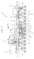
- a compaction and ballast removal machine for railway tracks in accordance with the present invention has been generally identified by reference numeral 1.
- the track is represented by a rail "R” and a succession of sleepers “T” spaced apart from each other by a distance "L” that is maintained as much as possible close to a predetermined value, but that inevitably suffers for a deviation from this value, due to positioning errors during the step of laying the track.
- the machine according to the invention can be preferably used for tracks of high-speed railway lines, for which the distance "L" between sleepers must be of 60 cm.
- the machine 1 comprises a car 2 having a frame 3 resting on wheels 3a, a driver's cab 4 mounted on frame 3 and a power unit 5 mounted on frame 3 as well.
- Car 2 can be of a substantially known type, and will not be herein described in detail.
- car 2 is of the type with two axles as shown in the drawings and mainly aims at quickly bringing the work equipment (compaction and ballast removal equipment) to the intervention region, and also aims at accommodating a technician and possibly supplying a sufficient mass during the compacting step.
- car 2 is moved forward along the direction of arrow "A" during the working steps of the machine 1.
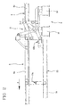
- the machine 1 is provided, under frame 3, with a supporting truck 6 having a front axle 6a and a rear axle 6b provided with railway wheels for engagement with the track, in such a manner that the supporting truck 6 can be slidably carried by the track.
- the supporting truck 6 is made of tubular metal elements, in particular a pair of longitudinal members 6c parallel to the rail "R" and two or more crosspieces not shown as they are perpendicular to the longitudinal members 6c and therefore cannot be seen.
- the wheels 6a, 6b are disposed at the front and rear ends of the supporting truck 6 relative to the advancing direction "A".
- the lifting means 7 acting on the supporting truck 6 to lift it up from the track when the machine 1 is being transferred or, more generally, when use of the machine 1 is not required for the compaction and ballast removal operations.
- the lifting means comprises oil-pressure cylinders operated by the power unit 5 and acting at the front and rear ends of the supporting truck 6.
- the oil-pressure cylinders are at least two in number for each end of the supporting truck 6.
- retaining means acting between frame 3 and the supporting truck 6 to prevent sliding of the supporting truck 6 relative to frame 3 along a direction parallel to the track.
- each longitudinal member 6c has a C-shaped guide facing the opposite longitudinal member 6c and slideably mounted between the two C-shaped guides is a portion of said slide 8, preferably an upper portion 8c, in such a manner that slide 8 appears to be guided and at the same time supported by the longitudinal members 6c of the supporting truck 6.
- Slide 8 too consists of a structure of the tubular metal type and is welded.
- second retaining means preferably one or more oil-pressure pistons operated by the power unit 5 and acting on opposite sides between slide 8 and the supporting truck 6 in order to enable mutual (forward or backward) sliding of said slide and truck during operation of the machine 1 and to lock them in a mutual steady position, for the purpose of allowing safe transfer of the machine 1, for example.
- a compaction unit 9 is installed on slide 8 and in particular on an end thereof opposite to the advancing direction "A" of the machine 1 ( Fig. 1 ); said unit 9 has two compacting elements 10 steadily spaced apart from each other by a distance substantially equal to the predetermined distance "L” existing between two sleepers "T".
- the compaction unit 9 comprises an articulated kinematic mechanism 11, preferably an articulated quadrilateral, acting between slide 8 and the compacting elements 10 to keep the latter oriented in a constant horizontal direction.
- the compaction unit 9 is of a substantially known type and will not be further described.
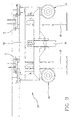
- the machine further comprises a ballast removing unit 12 operatively coupled to the compaction unit 9 to carry out ballast removal on a track portion that will be subsequently submitted to a compacting operation by means of said compaction unit 9.
- the ballast removing unit 12 comprises a ballast removing truck which is suitable to directly run on rails "R" by means of respective rolling members 14 which preferably comprise frusto-conical wheels of reduced sizes, as shown in the accompanying drawings.
- the ballast removing truck 13 is equipped with two pairs of ballast removing elements 15 arranged in such a manner that each pair is adapted to act on a respective rail "R".
- the ballast removing elements 15 can oscillate around respective oscillation axes "Y" parallel to each other and to the rails "R” for taking a work position at which they are inserted between the rail flange and the underlying crushed stones, and a rest position at which they move away from the rail and approach each other to enable transfer or advancing of the machine 1.
- the ballast removing elements 15 are of a substantially known type and therefore description of same will not be further analysed in depth.
- the ballast removing truck 13 too consists of a tubular metal structure that is welded.
- the ballast removing truck 13 comprises a respective pair of grasping jaws "P1" each of which is disposed at a position facing a rail "R” for reasons to be explained in the following.
- the ballast removing truck 13 can move on the track independently of slide 8 and of the supporting truck.
- suitable engagement portions 13a Fig. 2
- said engagement portions 13a comprise protrusions formed on slide 8 and adapted to be coupled to corresponding portions of the ballast removing truck 13 during raising of the supporting truck 6.
- slide 8 has a portal-shaped upper conformation defining an underlying space in which the ballast removing truck 13 is slidably housed.
- the machine 1 further comprises actuating means 16 acting between slide 8 and the ballast removing truck 13 for varying and/or steadily determining a mutual location of same along the direction denoted at A and parallel to the tracks during operation of the machine 1.
- the actuating means 16 comprises a oil-pressure operated adjustment piston 16a driven by the power unit 5 and having a first end rotatably fastened to slide 8 and a second end rotatably fastened to the ballast removing truck 13. Operation of said actuating means 16 carries out a mutual displacement between the ballast removing truck 13 and slide 8 while locking of the actuating means 16 gives rise to a (substantially stiff) steady coupling between the ballast removing truck 13 and slide 8 to a predetermined distance.
- the ballast removing truck 13 and slide 8 are integral with each other along a direction parallel to the track and therefore can only, translate by the same distance and jointly.
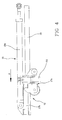
- the machine 1 further comprises an auxiliary truck slidably movable on the track to run close to and away from the ballast removing truck 13 and slide 8.
- the auxiliary truck 17, as shown in detail in Fig. 4 comprises a pair of slidable supports 17a, each of which is movable on a respective rail "R" by means of wheels, only one of which is shown in Fig. 4 , and a towing frame 17b connecting the slidable supports 17a and carried by said slidable supports 17a.
- Each of the slidable supports 17a is equipped with a respective pair of grasping jaws "P2" to be engaged with the corresponding underlying rail "R", for reasons to be explained in the following.
- the towing frame 17b is preferably rigidly connected to said slidable supports 17a. Both the grasping jaws "P1" of the ballast removing truck 13 and the grasping jaws "P2" of the slidable supports 17a are driven by oil-pressure actuators connected to and fluid-operated by the power unit 5.
- the machine 1 comprises advancing means 18 acting between the towing frame 17b and slide 8 so that they move close to and/or away from each other, or also in order to steadily fix a mutual position of same.
- the advancing means 18 can act between the towing frame 17b and the ballast removing truck 13.
- the advancing means 18 comprises a main oil-pressure piston 18a operated by the power unit 5 and having a first end rotatably connected to a central portion of the towing frame 17b, i.e. a portion of the towing frame 17b disposed at the track centre line, and a second end rotatably connected to slide 8.
- the towing frame 17b has a jutting out portion 19 slidably coupled, along a direction parallel to the track, to a guide portion 20 of slide 8 in such a manner that the jutting out portion 19 and guide portion 20 define a coupling of the sleeve type.
- the machine 1 is designed to work in an automatic and co-ordinate manner, utilising movements defined by couplings and mechanical abutments of the different parts that are movable relative to each other (as clarified in the following and shown in Figs. 6a-6d ); it should be noted, however, that in an alternative embodiment a system can be provided which comprises a processing unit the function of which is to control and govern operation of the compacting unit 9, the ballast removing unit 12, the actuators of the grasping jaws "P1" and “P2” and the actuating and advancing means, 16 and 18 respectively.
- the ballast removing unit 12 is equipped with sensor means (not shown) designed to detect a point indicating the centre line of a sleeper "T" during the advancing motion of the ballast removing unit 12 along the track. This enables the instant at which the ballast removing unit 12 exactly comes astride a sleeper "T” to be determined and, therefore, the instant at which the ballast removing elements 15 are disposed exactly astride the sleeper "T". Starting from that position, the ballast removing elements 15 can operate on the crushed stones surrounding the sleeper "T" without interfering with said sleeper.
- centre line of sleeper "T” it is intended the imaginary line dividing sleeper "T” into two symmetric parts perpendicularly to the major extension direction of the track.
- said sensor means is of the inductive type and detects metal elements being part of sleeper "T", such as bolts, track bolts, or portions of the attachment plate present on sleeper "T".
- said sensor means will be connected to the processing unit that will be able to store data relating to the centred position of the ballast removing unit 12 detected by the sensor means, so as to use these data again when in the following step the compaction unit 9 in turn will be located astride the same sleeper "T". In this way, it will not be necessary to correct the position of the compaction unit 9 as the data previously detected by the ballast removing unit 12 can be utilised.
- the machine 1 is transferred onto the track portion for which the operations concerning compaction of the crushed stones and ballast removal are provided to be carried out.
- the compaction unit 9 is operated in such a manner that the compacting elements 10 can work in a centred position relative to a sleeper "T".
- This manoeuvring that therefore adjusts positioning of slide 8 along the track in a precise manner, can be carried out manually, possibly with use, for co-operation, of said second retaining means (oil-pressure pistons acting from opposite positions) capable of driving a translation of the compaction unit 9 during the first centring.
- said means is shut down so that it does not interfere any longer with the following automatic movement of the machine.
- the described operation is not a problem because it is the only operation involving manual adjustment that is required and it exclusively takes place at the beginning of the machine setting up, while all the following operating steps carried out by the machine 1 are automatic.
- the adjustment piston 16a and main piston 18a are locked to a fixed position so as to make the slide 8, ballast removing truck 13 and auxiliary truck 17 integral with each other, while the grasping jaws "P2" of the slidable supports 17a are stably closed on the rail "R” so as to fasten both the slide 8 and the ballast removing truck 13 to a steady position.
- the compacting elements 10 can be safely operated starting compaction of the crushed stones at the sides of sleeper "T".
- the adjustment piston 16a is released and it moves the ballast removing truck 13 relative to slide 8 until bringing the ballast removing truck 13 close to a predetermined reference location ( Fig. 6 ).
- This reference location is preferably defined by an abutment position of the ballast removing truck 13 relative to slide 8, and more preferably obtained by mutual contact between two locators 30a, 30b shown by way of example and only for explanatory purposes in Fig. 6a where one of them is fastened to slide 8 and the other to the ballast removing truck 13.
- said abutment position is obtained by a maximum moving backward of the ballast removing truck 13 against the compaction unit relative to the advancing direction "A" of the machine 1.
- Fig. 6a helps in understanding the above description and shows a sequence of three consecutive sleepers "Tl"-"T3".
- distance “2L” represents the ideal distance (or project distance) between the centre line of sleeper T1 and the centre line of sleeper T'3 (ideally represented in chain line), should these sleepers be positioned on their path with no error.
- the two units would be to distance 2L from each other and could work astride the respective sleepers and at each cycle would advance by the distance 2L, so as to be positioned astride the following sleeper pair, respectively.
- the positioning error x of the real sleeper relative to the ideal sleeper can be both a positive error (i.e. a more forward position relative to the advancing direction A, as shown in Figs. 6a-6d ), and a negative error (i.e. the real sleeper is in a backward position relative to the ideal one along the advancing direction A).
- the mid-line axis of the 15 and the mid-line axis of the compacting elements 10 in said reference location are provided to be to their relative minimum distance equal to the ideal or project distance of the sleepers (for instance, T'3-T1) minus the maximum admissible positioning error "X" between said sleepers (position shown in Fig. 6a ).
- T'3-T1 the ideal or project distance of the sleepers
- X the maximum admissible positioning error
- the ballast removing truck 13 From this position of relative minimum distance between the mid-line axes, the ballast removing truck 13 will be able to move relative to the compaction unit 9 along the advancing way and direction A by a distance equal to at least (and generally slightly higher than) 2X, i.e. from the position of maximum error to the right of the project position to the position of maximum error to the left of the project position.
- the maximum stroke of the ballast removing truck 13 carried out by the adjustment piston 16a is equal to at least twice the maximum admissible error relating to distance "L" between the sleepers.
- the reference location defines a statistically extreme position, i.e. it represents a condition of maximum error by defect (2L-X).
- the ballast removing truck 13 is moved forward by the adjustment piston 16a along the track and in particular in the same way as the advancing direction "A" of the machine, until the sensor means detects that the ballast removing truck 13 is in a centred position relative to the second sleeper "T3" following sleeper "T1" on which the compaction unit 9 is operating.
- Corresponding to this position is an error value "x" (see Fig. 6b ); in case of use of a railway machine provided with an electronic control, the error "x" is sent to the processing unit and stored therein to be subsequently used. Shifting of the ballast removing truck 13 is allowed because the main piston 18a, that is presently locked, is connected to slide 8, while the ballast removing truck 13 can move being only governed by the adjustment piston 16a.
- the adjustment piston 16a is locked while jaws "P2" of the slidable supports 17a are released.
- the ballast removing truck 13 is fastened to rail "R” and slide 8 is locked to the ballast removing truck 13 since the adjustment piston 16a is locked.
- the main piston 18a is activated and it extends causing the auxiliary truck 17 to move forward in the advancing direction "A" of the machine, i.e. causing the auxiliary truck 17 to move away from slide 8 (i.e. from the compaction unit 9) and from the ballast removing truck 13 ( Fig. 6c ).
- auxiliary truck 17 By operating in this manner the auxiliary truck 17 will move forward by the distance 2L between two ideal sleepers, +/- the positioning error "x" of sleeper T3 already detected by the ballast removing unit 13.
- the stroke of the main piston 18a, or stroke of the compaction unit 9 is equal to the amount "2L+/-x", i.e. it is equal to the distance between the centre line of sleepers ideally laid, increased by the previously determined error "x" (or reduced by error "x", because error "x" can be by excess or by defect).
- the centre line of the compacting elements 10 is automatically in alignment with the centre line of sleeper "T3" relative to which the ballast removing elements 15 had been centred in the previous step, and consequently a further step for adjustment of the position of the compaction unit 9 is not necessary.
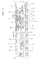
- the compacting elements 15 can therefore start a new step of compacting the crushed stones surrounding sleeper "T3" while the adjustment piston 16a is activated again (said piston being first brought to the end-of-stroke position to the right, i.e. to the distance "2L-X" from the mid-line axis of the compactor, and then the ballast removing truck 13 being driven in translation until the sensors detect the centre line of the following sleeper of interest) so as to align the ballast removing elements 15 relative to the underlying sleeper "T5", reaching a configuration of the type shown in Fig. 8 . As a matter of fact, the step sequence 6a-6d is repeated.
- the present invention can be advantageously used not only on compaction-ballast removal machines but also on machines designed to carry out other types of simultaneous working operations, more specifically machines having a first unit adapted to perform a first working and a second unit adapted to perform a second working and where one of the two operations calls for a longer intervention time than the other.
- the present invention achieves the intended purposes and overcomes the drawbacks encountered in the known art.
- determining the positioning error by means of the ballast removing unit and using said error value for the subsequent compacting operation this greatly reduces the required time for carrying out a compacting- ballast removing cycle.
- the ballast removing operation calls for a lower time than the compacting operation and in this context the invention aims at utilising the interval between completion of the ballast removing operation and completion of the compacting operation for performing the necessary surveys in order to determine said error value.
- the productivity of the machine according to the invention is substantially doubled as compared with that of the traditional machines, reaching a productivity of about 1 km of treated track for each working hour.
- the slidable mounting of the compacting and ballast removing units on the car allows said car to move at a constant speed without impairing the ballast removing and compacting operations, so that advancing of the machine is made more smooth and fluent, the intermittent advancing of the whole machine provided in the known art being eliminated.
Landscapes
- Engineering & Computer Science (AREA)
- Architecture (AREA)
- Civil Engineering (AREA)
- Structural Engineering (AREA)
- Machines For Laying And Maintaining Railways (AREA)
Applications Claiming Priority (1)
| Application Number | Priority Date | Filing Date | Title |
|---|---|---|---|
| ITMI20080139 ITMI20080139A1 (it) | 2008-01-30 | 2008-01-30 | Macchina operatrice per binari ferroviari |
Publications (2)
| Publication Number | Publication Date |
|---|---|
| EP2085517A2 true EP2085517A2 (de) | 2009-08-05 |
| EP2085517A3 EP2085517A3 (de) | 2011-04-20 |
Family
ID=40290152
Family Applications (1)
| Application Number | Title | Priority Date | Filing Date |
|---|---|---|---|
| EP09151631A Withdrawn EP2085517A3 (de) | 2008-01-30 | 2009-01-29 | Bearbeitungsmaschine für Schienenstrecken |
Country Status (2)
| Country | Link |
|---|---|
| EP (1) | EP2085517A3 (de) |
| IT (1) | ITMI20080139A1 (de) |
Cited By (1)
| Publication number | Priority date | Publication date | Assignee | Title |
|---|---|---|---|---|
| WO2016025154A1 (en) * | 2014-08-12 | 2016-02-18 | Harsco Technologies LLC | Rail vehicle having roller clamp assembly and towing arm |
Family Cites Families (3)
| Publication number | Priority date | Publication date | Assignee | Title |
|---|---|---|---|---|
| AT309505B (de) * | 1968-05-14 | 1973-08-27 | Plasser Bahnbaumasch Franz | Fahrbare Maschine zum Verdichten der Schotterbettung eines Gleises |
| AT345325B (de) * | 1975-06-20 | 1978-09-11 | Plasser Bahnbaumasch Franz | Gleisstopfmaschine, insbesondere gleisstopf- und nivelliermaschine |
| AT327268B (de) * | 1973-12-17 | 1976-01-26 | Plasser Bahnbaumasch Franz | Fahrbare maschine zum verdichten der schotterbettung eines gleises |
-
2008
- 2008-01-30 IT ITMI20080139 patent/ITMI20080139A1/it unknown
-
2009
- 2009-01-29 EP EP09151631A patent/EP2085517A3/de not_active Withdrawn
Cited By (2)
| Publication number | Priority date | Publication date | Assignee | Title |
|---|---|---|---|---|
| WO2016025154A1 (en) * | 2014-08-12 | 2016-02-18 | Harsco Technologies LLC | Rail vehicle having roller clamp assembly and towing arm |
| US9605386B2 (en) | 2014-08-12 | 2017-03-28 | Harsco Corporation | Rail vehicle having roller clamp assembly and towing arm |
Also Published As
| Publication number | Publication date |
|---|---|
| ITMI20080139A1 (it) | 2009-07-31 |
| EP2085517A3 (de) | 2011-04-20 |
Similar Documents
| Publication | Publication Date | Title |
|---|---|---|
| US5992329A (en) | Machine for welding at least one run of rail | |
| CA2288921C (en) | A method of tamping a track | |
| US5007350A (en) | Universal mobile track leveling, lining and tamping machine | |
| US4534295A (en) | Track tamping, leveling and lining operating unit | |
| US4301738A (en) | Apparatus for the replacement of rails of a track | |
| CA1092442A (en) | Tie preplating method and apparatus | |
| US4457234A (en) | Track lifting and lining device | |
| US4315129A (en) | Mobile apparatus for welding studs to rail base plates | |
| US4928599A (en) | Continuously advancing track leveling, lining and tamping machine | |
| DK152849B (da) | Koerbar sporunderstopningsmaskine, isaer maskine til samtidig nivellering og opretning af sporlegemers skinner. | |
| US5007349A (en) | Mobile track leveling, lining and tamping machine | |
| US4903608A (en) | Machine for laterally displacing a track | |
| JPH0130964B2 (de) | ||
| US8025013B2 (en) | Moving platform on rail vehicle | |
| CA1235330A (en) | Continuously advancing track leveling, lining and tamping machine | |
| US3286648A (en) | Rail renewal process | |
| SU1366066A3 (ru) | Передвижная выправочно-подбивочная машина | |
| US5778794A (en) | Machine for laying a railroad track having multiple-part carrier frame connected by a disengageable joint | |
| EP2971356A1 (de) | Schienenlager | |
| EP2085517A2 (de) | Bearbeitungsmaschine für Schienenstrecken | |
| US3943857A (en) | Track surfacing | |
| US5299505A (en) | Ballast tamping machine having pivotable and extendable auxiliary lifting and lining unit for branch track | |
| CN116276014A (zh) | 一种扣件螺栓松紧装置及作业方法 | |
| SU1297735A3 (ru) | Выправочно-подбивочно-отделочна машина | |
| JP7220839B2 (ja) | 軌きょう扛上装置 |
Legal Events
| Date | Code | Title | Description |
|---|---|---|---|
| PUAI | Public reference made under article 153(3) epc to a published international application that has entered the european phase |
Free format text: ORIGINAL CODE: 0009012 |
|
| AK | Designated contracting states |
Kind code of ref document: A2 Designated state(s): AT BE BG CH CY CZ DE DK EE ES FI FR GB GR HR HU IE IS IT LI LT LU LV MC MK MT NL NO PL PT RO SE SI SK TR |
|
| AX | Request for extension of the european patent |
Extension state: AL BA RS |
|
| PUAL | Search report despatched |
Free format text: ORIGINAL CODE: 0009013 |
|
| AK | Designated contracting states |
Kind code of ref document: A3 Designated state(s): AT BE BG CH CY CZ DE DK EE ES FI FR GB GR HR HU IE IS IT LI LT LU LV MC MK MT NL NO PL PT RO SE SI SK TR |
|
| AX | Request for extension of the european patent |
Extension state: AL BA RS |
|
| RIC1 | Information provided on ipc code assigned before grant |
Ipc: E01B 27/04 20060101ALI20110311BHEP Ipc: E01B 27/13 20060101AFI20110311BHEP |
|
| AKY | No designation fees paid | ||
| REG | Reference to a national code |
Ref country code: DE Ref legal event code: R108 |
|
| REG | Reference to a national code |
Ref country code: DE Ref legal event code: R108 Effective date: 20111228 |
|
| STAA | Information on the status of an ep patent application or granted ep patent |
Free format text: STATUS: THE APPLICATION IS DEEMED TO BE WITHDRAWN |
|
| 18D | Application deemed to be withdrawn |
Effective date: 20111021 |