EP2085529A2 - Vorrichtung zur Bereitstellung einer Hydraulikdichtung und -verbindung, insbesondere für zwei zusammenhängende Konstruktionssegmente eines Gebäudes - Google Patents
Vorrichtung zur Bereitstellung einer Hydraulikdichtung und -verbindung, insbesondere für zwei zusammenhängende Konstruktionssegmente eines Gebäudes Download PDFInfo
- Publication number
- EP2085529A2 EP2085529A2 EP08170748A EP08170748A EP2085529A2 EP 2085529 A2 EP2085529 A2 EP 2085529A2 EP 08170748 A EP08170748 A EP 08170748A EP 08170748 A EP08170748 A EP 08170748A EP 2085529 A2 EP2085529 A2 EP 2085529A2
- Authority
- EP
- European Patent Office
- Prior art keywords
- modular elements
- elements
- interconnection
- modular
- segments
- Prior art date
- Legal status (The legal status is an assumption and is not a legal conclusion. Google has not performed a legal analysis and makes no representation as to the accuracy of the status listed.)
- Granted
Links
- 230000006835 compression Effects 0.000 claims abstract description 23
- 238000007906 compression Methods 0.000 claims abstract description 23
- 239000000463 material Substances 0.000 claims abstract description 16
- 238000004519 manufacturing process Methods 0.000 claims description 7
- 229920000915 polyvinyl chloride Polymers 0.000 claims description 7
- 239000004800 polyvinyl chloride Substances 0.000 claims description 7
- 229920002943 EPDM rubber Polymers 0.000 claims description 4
- 229920003023 plastic Polymers 0.000 claims description 3
- 239000004033 plastic Substances 0.000 claims description 3
- 244000043261 Hevea brasiliensis Species 0.000 claims description 2
- 229920003052 natural elastomer Polymers 0.000 claims description 2
- 229920001194 natural rubber Polymers 0.000 claims description 2
- 229920002635 polyurethane Polymers 0.000 claims description 2
- 239000004814 polyurethane Substances 0.000 claims description 2
- 229920003051 synthetic elastomer Polymers 0.000 claims description 2
- 239000005061 synthetic rubber Substances 0.000 claims description 2
- XLYOFNOQVPJJNP-UHFFFAOYSA-N water Substances O XLYOFNOQVPJJNP-UHFFFAOYSA-N 0.000 description 14
- 238000009434 installation Methods 0.000 description 10
- 230000008595 infiltration Effects 0.000 description 7
- 238000001764 infiltration Methods 0.000 description 7
- 238000005266 casting Methods 0.000 description 5
- 239000004567 concrete Substances 0.000 description 5
- 239000011347 resin Substances 0.000 description 4
- 229920005989 resin Polymers 0.000 description 4
- 238000003466 welding Methods 0.000 description 3
- 230000004888 barrier function Effects 0.000 description 2
- 238000009415 formwork Methods 0.000 description 2
- 230000000670 limiting effect Effects 0.000 description 2
- 239000011150 reinforced concrete Substances 0.000 description 2
- 238000003860 storage Methods 0.000 description 2
- 229910000831 Steel Inorganic materials 0.000 description 1
- 208000027418 Wounds and injury Diseases 0.000 description 1
- 239000000853 adhesive Substances 0.000 description 1
- 230000001070 adhesive effect Effects 0.000 description 1
- 238000007664 blowing Methods 0.000 description 1
- 238000010276 construction Methods 0.000 description 1
- 230000008878 coupling Effects 0.000 description 1
- 238000010168 coupling process Methods 0.000 description 1
- 238000005859 coupling reaction Methods 0.000 description 1
- 230000006378 damage Effects 0.000 description 1
- 230000000694 effects Effects 0.000 description 1
- 230000005489 elastic deformation Effects 0.000 description 1
- 230000007613 environmental effect Effects 0.000 description 1
- 208000014674 injury Diseases 0.000 description 1
- 238000012423 maintenance Methods 0.000 description 1
- 239000002184 metal Substances 0.000 description 1
- 238000000034 method Methods 0.000 description 1
- 238000012986 modification Methods 0.000 description 1
- 230000004048 modification Effects 0.000 description 1
- 238000009417 prefabrication Methods 0.000 description 1
- 230000008569 process Effects 0.000 description 1
- 239000010959 steel Substances 0.000 description 1
Images



Classifications
-
- E—FIXED CONSTRUCTIONS
- E04—BUILDING
- E04B—GENERAL BUILDING CONSTRUCTIONS; WALLS, e.g. PARTITIONS; ROOFS; FLOORS; CEILINGS; INSULATION OR OTHER PROTECTION OF BUILDINGS
- E04B1/00—Constructions in general; Structures which are not restricted either to walls, e.g. partitions, or floors or ceilings or roofs
- E04B1/62—Insulation or other protection; Elements or use of specified material therefor
- E04B1/66—Sealings
- E04B1/68—Sealings of joints, e.g. expansion joints
- E04B1/6806—Waterstops
-
- E—FIXED CONSTRUCTIONS
- E04—BUILDING
- E04B—GENERAL BUILDING CONSTRUCTIONS; WALLS, e.g. PARTITIONS; ROOFS; FLOORS; CEILINGS; INSULATION OR OTHER PROTECTION OF BUILDINGS
- E04B1/00—Constructions in general; Structures which are not restricted either to walls, e.g. partitions, or floors or ceilings or roofs
- E04B1/62—Insulation or other protection; Elements or use of specified material therefor
- E04B1/66—Sealings
- E04B1/68—Sealings of joints, e.g. expansion joints
- E04B1/6812—Compressable seals of solid form
-
- E—FIXED CONSTRUCTIONS
- E04—BUILDING
- E04B—GENERAL BUILDING CONSTRUCTIONS; WALLS, e.g. PARTITIONS; ROOFS; FLOORS; CEILINGS; INSULATION OR OTHER PROTECTION OF BUILDINGS
- E04B1/00—Constructions in general; Structures which are not restricted either to walls, e.g. partitions, or floors or ceilings or roofs
- E04B1/62—Insulation or other protection; Elements or use of specified material therefor
- E04B1/66—Sealings
- E04B1/68—Sealings of joints, e.g. expansion joints
- E04B1/6813—Compressable seals of hollow form
Definitions
- the present invention relates to a device for providing a hydraulic seal and interconnection, particularly for two contiguous constructive segments of a building.
- strips made of plastic material whose central region has a tubular or bulb-like shape in order to facilitate the elastic deformations of such strip in the direction of the axis that connects the two segments; during the mutual movements of the two constructive segments connected by the strip, the central region of such strip can thus be deformed elastically even by a large extent, and can therefore follow, without the risk of breaking, the dimensional variations of the channel formed between such segments.
- connection between two contiguous strips occurs by mutually welding, for example by blowing air at high temperature or by means of an appropriately provided welding plate, two transverse ends of the two strips, and this is awkward and dangerous and requires a long time and a certain skill on the part of the installation technician. Moreover, this welding cannot be performed in the presence of water in the channel formed between the two constructive segments.
- the aim of the present invention is to solve the above noted technical problems, eliminating the drawbacks of the cited background art, by providing a device that allows to prevent infiltrations of water in the interspace or channel formed between two contiguous constructive segments of a building.
- an object of the invention is to ensure the seal between two contiguous constructive segments even in case of slight variations in their mutual distance.
- Another object of the invention is to provide a device which can be applied both to prefabricated segments and to segments provided directly on site.
- Another object of the invention is to provide a device which can be installed on site easily and quickly and without risks for the safety of the installation technician.
- Another object of the invention is to provide a device which can be installed even in the presence of water in the interspace or channel formed between the two constructive segments.
- Another object of the invention is to provide a device which can be used independently of the distance of the segments to be connected, of the pressure of the water to which they are subjected, and of the extent of the mutual movements to which they will be subj ected.
- Another object of the invention is to provide a device that is structurally simple and has low manufacturing costs.
- a device for providing a hydraulic seal and interconnection particularly for two contiguous constructive segments of a building, characterized in that it comprises a plurality of modular elements made of elastically deformable material, which can be mutually associated in series and are arranged so that their lateral surfaces face said constructive segments, said modular elements being closed in a vise-like configuration between at least two elements for interconnection and compression, which are arranged respectively adjacent to the upper surface and the lower surface of said modular elements.
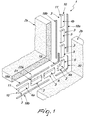
- the reference numeral 1 designates a device for providing a hydraulic seal and interconnection, particularly for two contiguous constructive segments 2a, 2b of a building.
- the device 1 comprises a plurality of modular elements 3 made of elastically deformable material, which can be mutually associated in series with respect to each other and are arranged so that their lateral surfaces 4a and 4b face the constructive segments 2a and 2b.
- the modular elements 3 can be made of natural rubber or synthetic rubber, such as for example the material known by the acronym PVC (Poly Vinyl Chloride) or the material known by the acronym EPDM (Ethylene Propylene Diene Monomer), or polyurethane, molded or poured.
- PVC Poly Vinyl Chloride
- EPDM Ethylene Propylene Diene Monomer
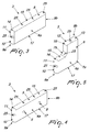
- a first embodiment of modular element 3, illustrated for example in Figure 3 is constituted by a first block 5, which is substantially shaped like a parallelepiped and can be interposed between two constructive segments 2a and 2b in their straight portions.
- An angular modular element 3, illustrated for example in Figure 5 is constituted by a second block 6, which in a side view is approximately L-shaped, preferably with an outer vertex 7a and an inner vertex 7b which are rounded, and can be interposed between two constructive segments 2a and 2b at the 90° bends of their perimetric edge.
- the modular elements 3 can in any case have, in a side view, the desired shape, for example a curved shape, so as to adapt to the specific profile of the constructive segments 2a, 2b to be connected.
- protrusions 8 protrude from the lateral surfaces 4a and 4b of the modular elements 3, preferably have an approximately T-shaped transverse cross-section and can be embedded in the constructive segments 2a and 2b during concrete casting in order to couple the modular elements 3 to the segments 2a and 2b and facilitate the installation of the device 1.
- the protrusions 8 can be provided monolithically with the respective modular element 3, or can be associated with the latter by means of appropriately provided fixing means, such as for example appropriately provided adhesives, or by interlocking.
- the modular elements 3 have, at a first end 9a thereof, one or more first teeth 10 and/or one or more first seats 11, which can be associated respectively with a corresponding number of complementarily shaped second seats 12 and/or second teeth 13, provided at a second end 9b of one separate modular element 3.
- the modular elements 3 have, at and along part of the first end 9a, a first tooth 10, which is followed axially by a complementarily shaped first seat 11.
- a first recess 14 is thus provided which forms the first seat 11, which has a preferably approximately elliptical plan shape and is obtained starting from an upper surface 15 of the modular element 3 and affects it along approximately half of its height.
- the first recess 14, and therefore the first seat 11 and the first tooth 10 formed by them can have a substantially rectangular or square plan shape.
- a second recess 16 which is similar to the first recess 14 and forms a second seat 12, which is shaped complementarily to the first tooth 10, and a second tooth 13, which is shaped complementarily to the first seat 11.
- the various modular elements 3 can be connected axially in series to each other by arranging the first tooth 10 and the contiguous first seat 11 of one modular element 3 respectively in engagement with the second seat 12 and the adjacent second tooth 13 of one distinct and contiguous modular element 3.
- the engagement of the first and second teeth 10 and 13 respectively in the first and second seats 11 and 12 increases the length and the tortuousness of the contact surface between two contiguous modular elements 3, making any infiltration of water in the interspace between the two constructive segments 2a and 2b, through such contact surface, more difficult.
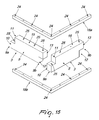
- the mutual engagement of the first and second teeth 10 and 13 respectively in the first and second seats 11 and 12 allows to connect in series to each other two modular elements 3, arranging them so that their longitudinal axes are both mutually aligned, as shown for example in Figures 1 and 2 , and mutually inclined, as shown for example in Figure 15 , maintaining the continuity of the connection between the modular elements 3; in this manner it is thus possible to use the device 1 according to the invention to provide the interconnection and hydraulic seal between two constructive segments 2a and 2b, whose mutually facing perimetric edges have, in plan view, a desired profile.
- Each pair of the mutually contiguous modular elements 3 is interposed between at least two interconnection and compression elements, which are arranged respectively adjacent to the upper surface 15 and a lower surface 17 of the modular elements 3.
- the interconnection and compression elements comprise two first profiles 18a, 18b, which are substantially mutually identical; the first profiles 18a and 18b are advantageously approximately rectilinear, have a preferably approximately square transverse cross-section and are narrower than the first blocks 5.
- first profiles 18a, 18b can have a desired shape in plan view, so as to be able to mutually connect in series the modular elements 3 according to a desired arrangement in plan view; for example, Figure 15 illustrates the case in which the first profiles 18a and 18b have a substantially L-shaped plan configuration, so as to be able to mutually connect two modular elements 3 that are arranged, in plan view, approximately at right angles to each other.
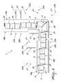
- such interconnection and compression elements further comprise a second profile 19, which is approximately L-shaped in a side view, with a rounded wing connection region, and is at least partially shaped complementarily with respect to the upper surface 15 of the second blocks 6, so that it can be positioned adjacent to it during use.
- the interconnection and compression elements further comprise a third profile 20, which is approximately L-shaped in a side view with a rounded wing connection region, and is at least partially shaped complementarily with respect to the lower surface 17 of the second blocks 6, so that during use it can be arranged adjacent thereto.
- the second profile 19 and the third profile 20 protrude, with their free ends, approximately at right angles from the first end 9a and from the second end 9b of the second block 6, so that they can be arranged adjacent to the upper surface 15 or lower surface 17 of two additional first blocks 5, which are axially associated in series respectively with the first and second ends 9a and 9b of the second block 6.
- the mutual distance of such interconnection and compression elements can be modified selectively by way of appropriately provided adjustment means, so as to reduce or increase elastically the height of the modular elements 3 and accordingly respectively increase or reduce elastically their width, so as to adjust the pressure of the lateral surfaces 4a and 4b thereof against the constructive segments 2a and 2b.
- such adjustment means are constituted by tension elements 21, with appropriately threaded ends 21a, 21b of which it is possible to associate respectively two nuts 22a, 22b, with the optional interposition of appropriately provided washers 23a, 23b; the tension elements 21 can be inserted in appropriately provided first holes 24, which are formed transversely to the first, second and third profiles, and in facing second holes 25, which are provided axially with respect to the modular elements 3.
- At least two second holes 25 are formed respectively axially with respect to the first tooth 10 and the second tooth 13, in such a position that they face each other once two modular elements 3 are associated.
- At least one second hole 25 is formed at the inner vertex 7b and at the outer vertex 7a of the second block 6.
- the device 1 can be used to mutually connect two prefabricated constructive segments 2a and 2b.
- a plurality of modular elements 3 can be arranged in series to each other so as to follow the mutually facing perimetric edges of the two constructive segments 2a and 2b, and can thus be mutually connected by means of the interconnection and compression elements.
- the compression of the modular elements 3 also causes their simultaneous widening in the direction of the axis that connects the two constructive segments 2a and 2b, so that the lateral surfaces 4a and 4b of the modular elements 3 abut against the mutually facing surfaces of the segments 2a and 2b, coupling by friction to them.
- the compression of the modular elements 3 further causes their simultaneous elongation in a longitudinal direction, thus increasing the fastening between two contiguous modular elements 3.
- the modular elements 3, fixed to them by way of the protrusions 8, can be compressed, by means of the interconnection and compression elements, until the desired contact pressure is achieved between the lateral surfaces 4a and 4b thereof and the mutually facing surfaces of the constructive segments 2a and 2b.
- the contact pressure is adjusted so that the modular elements 3, after their installation, are compressed elastically in the direction of the line that connects the two constructive segments 2a and 2b, so that if the distance between the segments increases, for example due to thermal expansions or ground movements, the modular elements 3 expand laterally, remaining in contact with the constructive segments 2a and 2b and thus ensuring that the hydraulic seal is maintained.
- the invention has achieved the proposed aim and objects, a device for providing a hydraulic seal and interconnection, particularly for two contiguous constructive segments of a building, having been provided which is capable of preventing effectively water infiltrations into the interspace or channel formed between the constructive segments.
- the device according to the invention allows to calibrate even locally the pressure on the segments, so as to adjust the hydraulic seal as a function for example of the depth of use.
- the device according to the invention can be disassembled and/or adjusted even after its installation on site, thus allowing easy maintenance thereof and allowing the possibility to modify the contact pressure at a chosen time depending for example on any variations in the environmental conditions.
- connection among the various modular elements can be provided easily and quickly by way of the interconnection and compression elements and therefore does not require the use of tools with hot parts, which therefore are potentially dangerous for the user, as instead occurs for strips of plastic material of the known type; this increases speed and convenience in installation, reduces the risk of injury to the installation technician, and further allows installation even in the presence of water in the interspace formed between the two constructive segments.
- the device according to the invention further allows to provide directly on site any form and length of the seal, both in a horizontal direction and in a vertical direction, without the need for external prefabrication and by using a limited variety of modular elements.
- the hydraulic seal between them and the two constructive segments can be achieved independently of the material of which the segments are made; this allows to use the device according to the invention also in combination with constructive segments made of materials other than reinforced concrete, such as for example steel.
- the modular components by way of their limited dimensions, can be transported and installed easily even in tight spaces that are difficult to reach.
- the device according to the invention being constituted by modular elements that can be mutually associated in the desired manner, adapts without problems to any mismatches between the design and the real building.
- hydraulic seal is achieved independently of the length of the channel formed between the two constructive segments.
- the production costs of the device according to the invention remain modest, since the device is provided only by means of components that are easy to manufacture and/or assemble.
- the second profile 19 and the third profile 20 can be shorter respectively than the upper surface 15 and lower surface 17 of the second block 6, so that they can be associated with the latter only respectively at the inner vertex 7b and at the outer vertex 7a thereof, without protruding from the first or second end of the second block 6.
- modular elements 3 and the interconnection and compression elements can have the desired plan shape, so as to allow to connect them in series according to the desired plan configuration.
Landscapes
- Engineering & Computer Science (AREA)
- Architecture (AREA)
- Physics & Mathematics (AREA)
- Electromagnetism (AREA)
- Civil Engineering (AREA)
- Structural Engineering (AREA)
- Gasket Seals (AREA)
- Installation Of Indoor Wiring (AREA)
Applications Claiming Priority (1)
| Application Number | Priority Date | Filing Date | Title |
|---|---|---|---|
| ITVE20080006 ITVE20080006A1 (it) | 2008-01-30 | 2008-01-30 | Dispositivo di interconnessione e tenuta idraulica, particolarmente per due conci costruttivi contigui di una struttura edile |
Publications (3)
| Publication Number | Publication Date |
|---|---|
| EP2085529A2 true EP2085529A2 (de) | 2009-08-05 |
| EP2085529A3 EP2085529A3 (de) | 2011-08-10 |
| EP2085529B1 EP2085529B1 (de) | 2012-08-22 |
Family
ID=40290474
Family Applications (1)
| Application Number | Title | Priority Date | Filing Date |
|---|---|---|---|
| EP20080170748 Not-in-force EP2085529B1 (de) | 2008-01-30 | 2008-12-04 | Vorrichtung zur Bereitstellung einer Hydraulikdichtung und -verbindung, insbesondere für zwei zusammenhängende Konstruktionssegmente eines Gebäudes |
Country Status (2)
| Country | Link |
|---|---|
| EP (1) | EP2085529B1 (de) |
| IT (1) | ITVE20080006A1 (de) |
Cited By (2)
| Publication number | Priority date | Publication date | Assignee | Title |
|---|---|---|---|---|
| EP2913470A4 (de) * | 2012-10-26 | 2016-08-03 | Korea Inst Construction Tech | Füllmaterial, fenster und füllverfahren |
| EP3524744A1 (de) * | 2018-02-08 | 2019-08-14 | glatthaar-technology gmbh & co. kg | Pressdichtung, dichtungsanordnung und bauwerk mit pressdichtung |
Family Cites Families (5)
| Publication number | Priority date | Publication date | Assignee | Title |
|---|---|---|---|---|
| US2374186A (en) * | 1941-03-04 | 1945-04-24 | Albert C Fischer | Extrusion controlled water-stop expansion joint |
| GB1067976A (en) * | 1965-03-05 | 1967-05-10 | Redfern Holdings Ltd | Improvements in joint sealing gaskets for building panels |
| DE4123282A1 (de) * | 1991-07-13 | 1993-01-14 | Irbit Research & Consulting Ag | Dichtelement |
| IT1279338B1 (it) * | 1995-07-28 | 1997-12-09 | Volteco Spa | Barriera anti-acqua particolarmente per opere in calcestruzzo |
| DE10146678A1 (de) * | 2001-09-21 | 2003-04-10 | Zementol Gmbh | Fugenband für Betonbauwerke |
-
2008
- 2008-01-30 IT ITVE20080006 patent/ITVE20080006A1/it unknown
- 2008-12-04 EP EP20080170748 patent/EP2085529B1/de not_active Not-in-force
Cited By (2)
| Publication number | Priority date | Publication date | Assignee | Title |
|---|---|---|---|---|
| EP2913470A4 (de) * | 2012-10-26 | 2016-08-03 | Korea Inst Construction Tech | Füllmaterial, fenster und füllverfahren |
| EP3524744A1 (de) * | 2018-02-08 | 2019-08-14 | glatthaar-technology gmbh & co. kg | Pressdichtung, dichtungsanordnung und bauwerk mit pressdichtung |
Also Published As
| Publication number | Publication date |
|---|---|
| EP2085529B1 (de) | 2012-08-22 |
| EP2085529A3 (de) | 2011-08-10 |
| ITVE20080006A1 (it) | 2009-07-31 |
Similar Documents
| Publication | Publication Date | Title |
|---|---|---|
| KR101975763B1 (ko) | 양방향 정착 커플러와 인서트 고정장치 및 고점착 유연성 겔 방수재를 이용한 암거 구조물 시공방법 | |
| KR101125549B1 (ko) | 단열재가 부착된 트러스 데크 플레이트를 이용한 슬래브 시공방법 | |
| KR101258188B1 (ko) | 건축물 콘크리트벽 단열재 연결장치 | |
| KR101493767B1 (ko) | 곡률 조정이 가능한 곡선형 psc거더 제작용 강재거푸집 및 이를 이용한 곡선형 psc거더 제작방법 | |
| KR102259453B1 (ko) | 건축용 벽체 일체형 거푸집 조립체 | |
| KR101165563B1 (ko) | 프리캐스트 콘크리트용 가변형 강재형틀 | |
| EP2085529B1 (de) | Vorrichtung zur Bereitstellung einer Hydraulikdichtung und -verbindung, insbesondere für zwei zusammenhängende Konstruktionssegmente eines Gebäudes | |
| KR20080004691U (ko) | 유형 측구 제조용 거푸집 | |
| CA2748486A1 (en) | Construction system for buildings | |
| KR101549418B1 (ko) | 쐐기 형상의 지수판 및 이를 사용하는 콘크리트 슬래브 타설용 매립형 신축이음매 거푸집 | |
| KR20190081117A (ko) | 양중·설치가 용이한 합성 프리캐스트 벽체 시스템 | |
| KR20150131904A (ko) | 긴장 겸용 강재를 이용한 프리캐스트 콘크리트 그레이팅용 수로 세그먼트 구조물 및 이의 시공방법 | |
| KR101854653B1 (ko) | 노출콘크리트 공법 기반 콘크리트 구조물 시공방법 | |
| KR101431749B1 (ko) | 미분리형 블록 거푸집 조립체 | |
| KR20190062806A (ko) | 수평전단보강수단을 이용한 이중합성 pc벽체 구조 | |
| US20070056242A1 (en) | Connector for concrete panels | |
| GB2394968A (en) | Elements for constructing underground chambers | |
| KR101437672B1 (ko) | 조립식 피시빔 교량 구조물 및 그 시공방법 | |
| KR101301073B1 (ko) | 긴장재를 이용한 부벽식 개거수로 및 그 시공방법 | |
| KR101741070B1 (ko) | 그레이팅 | |
| KR100438401B1 (ko) | 보일러 온돌판넬 | |
| JP5258662B2 (ja) | 外壁パネル間目地接合部構造 | |
| KR101059542B1 (ko) | 맨홀 | |
| KR20000067735A (ko) | 콘크리트 구조물용 슬래브판 | |
| KR101812560B1 (ko) | 건축 시공방법 |
Legal Events
| Date | Code | Title | Description |
|---|---|---|---|
| PUAI | Public reference made under article 153(3) epc to a published international application that has entered the european phase |
Free format text: ORIGINAL CODE: 0009012 |
|
| AK | Designated contracting states |
Kind code of ref document: A2 Designated state(s): AT BE BG CH CY CZ DE DK EE ES FI FR GB GR HR HU IE IS IT LI LT LU LV MC MT NL NO PL PT RO SE SI SK TR |
|
| AX | Request for extension of the european patent |
Extension state: AL BA MK RS |
|
| PUAL | Search report despatched |
Free format text: ORIGINAL CODE: 0009013 |
|
| AK | Designated contracting states |
Kind code of ref document: A3 Designated state(s): AT BE BG CH CY CZ DE DK EE ES FI FR GB GR HR HU IE IS IT LI LT LU LV MC MT NL NO PL PT RO SE SI SK TR |
|
| AX | Request for extension of the european patent |
Extension state: AL BA MK RS |
|
| RIC1 | Information provided on ipc code assigned before grant |
Ipc: E04B 1/68 20060101AFI20110706BHEP |
|
| 17P | Request for examination filed |
Effective date: 20110922 |
|
| GRAP | Despatch of communication of intention to grant a patent |
Free format text: ORIGINAL CODE: EPIDOSNIGR1 |
|
| AKX | Designation fees paid |
Designated state(s): AT BE BG CH CY CZ DE DK EE ES FI FR GB GR HR HU IE IS IT LI LT LU LV MC MT NL NO PL PT RO SE SI SK TR |
|
| GRAS | Grant fee paid |
Free format text: ORIGINAL CODE: EPIDOSNIGR3 |
|
| GRAA | (expected) grant |
Free format text: ORIGINAL CODE: 0009210 |
|
| AK | Designated contracting states |
Kind code of ref document: B1 Designated state(s): AT BE BG CH CY CZ DE DK EE ES FI FR GB GR HR HU IE IS IT LI LT LU LV MC MT NL NO PL PT RO SE SI SK TR |
|
| REG | Reference to a national code |
Ref country code: GB Ref legal event code: FG4D |
|
| REG | Reference to a national code |
Ref country code: CH Ref legal event code: EP |
|
| REG | Reference to a national code |
Ref country code: IE Ref legal event code: FG4D |
|
| REG | Reference to a national code |
Ref country code: AT Ref legal event code: REF Ref document number: 572115 Country of ref document: AT Kind code of ref document: T Effective date: 20120915 |
|
| REG | Reference to a national code |
Ref country code: CH Ref legal event code: NV Representative=s name: BRAUNPAT BRAUN EDER AG |
|
| REG | Reference to a national code |
Ref country code: DE Ref legal event code: R096 Ref document number: 602008018171 Country of ref document: DE Effective date: 20121018 |
|
| REG | Reference to a national code |
Ref country code: NL Ref legal event code: VDEP Effective date: 20120822 |
|
| REG | Reference to a national code |
Ref country code: AT Ref legal event code: MK05 Ref document number: 572115 Country of ref document: AT Kind code of ref document: T Effective date: 20120822 |
|
| REG | Reference to a national code |
Ref country code: LT Ref legal event code: MG4D Effective date: 20120822 |
|
| PG25 | Lapsed in a contracting state [announced via postgrant information from national office to epo] |
Ref country code: AT Free format text: LAPSE BECAUSE OF FAILURE TO SUBMIT A TRANSLATION OF THE DESCRIPTION OR TO PAY THE FEE WITHIN THE PRESCRIBED TIME-LIMIT Effective date: 20120822 Ref country code: CY Free format text: LAPSE BECAUSE OF FAILURE TO SUBMIT A TRANSLATION OF THE DESCRIPTION OR TO PAY THE FEE WITHIN THE PRESCRIBED TIME-LIMIT Effective date: 20120822 Ref country code: HR Free format text: LAPSE BECAUSE OF FAILURE TO SUBMIT A TRANSLATION OF THE DESCRIPTION OR TO PAY THE FEE WITHIN THE PRESCRIBED TIME-LIMIT Effective date: 20120822 Ref country code: FI Free format text: LAPSE BECAUSE OF FAILURE TO SUBMIT A TRANSLATION OF THE DESCRIPTION OR TO PAY THE FEE WITHIN THE PRESCRIBED TIME-LIMIT Effective date: 20120822 Ref country code: NO Free format text: LAPSE BECAUSE OF FAILURE TO SUBMIT A TRANSLATION OF THE DESCRIPTION OR TO PAY THE FEE WITHIN THE PRESCRIBED TIME-LIMIT Effective date: 20121122 Ref country code: LT Free format text: LAPSE BECAUSE OF FAILURE TO SUBMIT A TRANSLATION OF THE DESCRIPTION OR TO PAY THE FEE WITHIN THE PRESCRIBED TIME-LIMIT Effective date: 20120822 Ref country code: IS Free format text: LAPSE BECAUSE OF FAILURE TO SUBMIT A TRANSLATION OF THE DESCRIPTION OR TO PAY THE FEE WITHIN THE PRESCRIBED TIME-LIMIT Effective date: 20121222 |
|
| PG25 | Lapsed in a contracting state [announced via postgrant information from national office to epo] |
Ref country code: BE Free format text: LAPSE BECAUSE OF FAILURE TO SUBMIT A TRANSLATION OF THE DESCRIPTION OR TO PAY THE FEE WITHIN THE PRESCRIBED TIME-LIMIT Effective date: 20120822 Ref country code: PT Free format text: LAPSE BECAUSE OF FAILURE TO SUBMIT A TRANSLATION OF THE DESCRIPTION OR TO PAY THE FEE WITHIN THE PRESCRIBED TIME-LIMIT Effective date: 20121224 Ref country code: SE Free format text: LAPSE BECAUSE OF FAILURE TO SUBMIT A TRANSLATION OF THE DESCRIPTION OR TO PAY THE FEE WITHIN THE PRESCRIBED TIME-LIMIT Effective date: 20120822 Ref country code: GR Free format text: LAPSE BECAUSE OF FAILURE TO SUBMIT A TRANSLATION OF THE DESCRIPTION OR TO PAY THE FEE WITHIN THE PRESCRIBED TIME-LIMIT Effective date: 20121123 Ref country code: SI Free format text: LAPSE BECAUSE OF FAILURE TO SUBMIT A TRANSLATION OF THE DESCRIPTION OR TO PAY THE FEE WITHIN THE PRESCRIBED TIME-LIMIT Effective date: 20120822 Ref country code: LV Free format text: LAPSE BECAUSE OF FAILURE TO SUBMIT A TRANSLATION OF THE DESCRIPTION OR TO PAY THE FEE WITHIN THE PRESCRIBED TIME-LIMIT Effective date: 20120822 |
|
| PG25 | Lapsed in a contracting state [announced via postgrant information from national office to epo] |
Ref country code: NL Free format text: LAPSE BECAUSE OF FAILURE TO SUBMIT A TRANSLATION OF THE DESCRIPTION OR TO PAY THE FEE WITHIN THE PRESCRIBED TIME-LIMIT Effective date: 20120822 |
|
| PG25 | Lapsed in a contracting state [announced via postgrant information from national office to epo] |
Ref country code: DK Free format text: LAPSE BECAUSE OF FAILURE TO SUBMIT A TRANSLATION OF THE DESCRIPTION OR TO PAY THE FEE WITHIN THE PRESCRIBED TIME-LIMIT Effective date: 20120822 Ref country code: CZ Free format text: LAPSE BECAUSE OF FAILURE TO SUBMIT A TRANSLATION OF THE DESCRIPTION OR TO PAY THE FEE WITHIN THE PRESCRIBED TIME-LIMIT Effective date: 20120822 Ref country code: RO Free format text: LAPSE BECAUSE OF FAILURE TO SUBMIT A TRANSLATION OF THE DESCRIPTION OR TO PAY THE FEE WITHIN THE PRESCRIBED TIME-LIMIT Effective date: 20120822 Ref country code: ES Free format text: LAPSE BECAUSE OF FAILURE TO SUBMIT A TRANSLATION OF THE DESCRIPTION OR TO PAY THE FEE WITHIN THE PRESCRIBED TIME-LIMIT Effective date: 20121203 Ref country code: EE Free format text: LAPSE BECAUSE OF FAILURE TO SUBMIT A TRANSLATION OF THE DESCRIPTION OR TO PAY THE FEE WITHIN THE PRESCRIBED TIME-LIMIT Effective date: 20120822 |
|
| PG25 | Lapsed in a contracting state [announced via postgrant information from national office to epo] |
Ref country code: PL Free format text: LAPSE BECAUSE OF FAILURE TO SUBMIT A TRANSLATION OF THE DESCRIPTION OR TO PAY THE FEE WITHIN THE PRESCRIBED TIME-LIMIT Effective date: 20120822 Ref country code: SK Free format text: LAPSE BECAUSE OF FAILURE TO SUBMIT A TRANSLATION OF THE DESCRIPTION OR TO PAY THE FEE WITHIN THE PRESCRIBED TIME-LIMIT Effective date: 20120822 |
|
| PLBE | No opposition filed within time limit |
Free format text: ORIGINAL CODE: 0009261 |
|
| STAA | Information on the status of an ep patent application or granted ep patent |
Free format text: STATUS: NO OPPOSITION FILED WITHIN TIME LIMIT |
|
| 26N | No opposition filed |
Effective date: 20130523 |
|
| PG25 | Lapsed in a contracting state [announced via postgrant information from national office to epo] |
Ref country code: MC Free format text: LAPSE BECAUSE OF NON-PAYMENT OF DUE FEES Effective date: 20121231 Ref country code: BG Free format text: LAPSE BECAUSE OF FAILURE TO SUBMIT A TRANSLATION OF THE DESCRIPTION OR TO PAY THE FEE WITHIN THE PRESCRIBED TIME-LIMIT Effective date: 20121122 |
|
| REG | Reference to a national code |
Ref country code: DE Ref legal event code: R097 Ref document number: 602008018171 Country of ref document: DE Effective date: 20130523 |
|
| REG | Reference to a national code |
Ref country code: IE Ref legal event code: MM4A |
|
| PG25 | Lapsed in a contracting state [announced via postgrant information from national office to epo] |
Ref country code: IE Free format text: LAPSE BECAUSE OF NON-PAYMENT OF DUE FEES Effective date: 20121204 |
|
| PG25 | Lapsed in a contracting state [announced via postgrant information from national office to epo] |
Ref country code: MT Free format text: LAPSE BECAUSE OF FAILURE TO SUBMIT A TRANSLATION OF THE DESCRIPTION OR TO PAY THE FEE WITHIN THE PRESCRIBED TIME-LIMIT Effective date: 20120822 |
|
| PG25 | Lapsed in a contracting state [announced via postgrant information from national office to epo] |
Ref country code: TR Free format text: LAPSE BECAUSE OF FAILURE TO SUBMIT A TRANSLATION OF THE DESCRIPTION OR TO PAY THE FEE WITHIN THE PRESCRIBED TIME-LIMIT Effective date: 20120822 |
|
| PG25 | Lapsed in a contracting state [announced via postgrant information from national office to epo] |
Ref country code: LU Free format text: LAPSE BECAUSE OF NON-PAYMENT OF DUE FEES Effective date: 20121204 |
|
| PG25 | Lapsed in a contracting state [announced via postgrant information from national office to epo] |
Ref country code: HU Free format text: LAPSE BECAUSE OF FAILURE TO SUBMIT A TRANSLATION OF THE DESCRIPTION OR TO PAY THE FEE WITHIN THE PRESCRIBED TIME-LIMIT Effective date: 20081204 |
|
| REG | Reference to a national code |
Ref country code: DE Ref legal event code: R082 Ref document number: 602008018171 Country of ref document: DE Representative=s name: GRAMM, LINS & PARTNER PATENT- UND RECHTSANWAEL, DE |
|
| REG | Reference to a national code |
Ref country code: FR Ref legal event code: PLFP Year of fee payment: 8 |
|
| PGFP | Annual fee paid to national office [announced via postgrant information from national office to epo] |
Ref country code: CH Payment date: 20151229 Year of fee payment: 8 Ref country code: GB Payment date: 20151027 Year of fee payment: 8 |
|
| PGFP | Annual fee paid to national office [announced via postgrant information from national office to epo] |
Ref country code: FR Payment date: 20151023 Year of fee payment: 8 |
|
| PGFP | Annual fee paid to national office [announced via postgrant information from national office to epo] |
Ref country code: DE Payment date: 20151223 Year of fee payment: 8 |
|
| REG | Reference to a national code |
Ref country code: DE Ref legal event code: R119 Ref document number: 602008018171 Country of ref document: DE |
|
| REG | Reference to a national code |
Ref country code: CH Ref legal event code: PL |
|
| GBPC | Gb: european patent ceased through non-payment of renewal fee |
Effective date: 20161204 |
|
| REG | Reference to a national code |
Ref country code: FR Ref legal event code: ST Effective date: 20170831 |
|
| PG25 | Lapsed in a contracting state [announced via postgrant information from national office to epo] |
Ref country code: LI Free format text: LAPSE BECAUSE OF NON-PAYMENT OF DUE FEES Effective date: 20161231 Ref country code: CH Free format text: LAPSE BECAUSE OF NON-PAYMENT OF DUE FEES Effective date: 20161231 Ref country code: FR Free format text: LAPSE BECAUSE OF NON-PAYMENT OF DUE FEES Effective date: 20170102 |
|
| PG25 | Lapsed in a contracting state [announced via postgrant information from national office to epo] |
Ref country code: DE Free format text: LAPSE BECAUSE OF NON-PAYMENT OF DUE FEES Effective date: 20170701 Ref country code: GB Free format text: LAPSE BECAUSE OF NON-PAYMENT OF DUE FEES Effective date: 20161204 |
|
| PGFP | Annual fee paid to national office [announced via postgrant information from national office to epo] |
Ref country code: IT Payment date: 20191210 Year of fee payment: 12 |
|
| PG25 | Lapsed in a contracting state [announced via postgrant information from national office to epo] |
Ref country code: IT Free format text: LAPSE BECAUSE OF NON-PAYMENT OF DUE FEES Effective date: 20201204 |