EP2085530A1 - Ceiling frame for holding ceiling panels having a cross runner with a locally impressed nose section - Google Patents
Ceiling frame for holding ceiling panels having a cross runner with a locally impressed nose section Download PDFInfo
- Publication number
- EP2085530A1 EP2085530A1 EP08075069A EP08075069A EP2085530A1 EP 2085530 A1 EP2085530 A1 EP 2085530A1 EP 08075069 A EP08075069 A EP 08075069A EP 08075069 A EP08075069 A EP 08075069A EP 2085530 A1 EP2085530 A1 EP 2085530A1
- Authority
- EP
- European Patent Office
- Prior art keywords
- folding line
- hollow profile
- impression
- nose section
- cross runner
- Prior art date
- Legal status (The legal status is an assumption and is not a legal conclusion. Google has not performed a legal analysis and makes no representation as to the accuracy of the status listed.)
- Withdrawn
Links
- 230000008878 coupling Effects 0.000 claims abstract description 12
- 238000010168 coupling process Methods 0.000 claims abstract description 12
- 238000005859 coupling reaction Methods 0.000 claims abstract description 12
- 238000004080 punching Methods 0.000 claims description 9
- 238000004519 manufacturing process Methods 0.000 claims description 4
- 239000000463 material Substances 0.000 claims description 4
- 238000000034 method Methods 0.000 claims 3
- 238000005452 bending Methods 0.000 description 10
- 230000000694 effects Effects 0.000 description 3
- 229910000831 Steel Inorganic materials 0.000 description 1
- 238000005520 cutting process Methods 0.000 description 1
- 230000001419 dependent effect Effects 0.000 description 1
- 230000003292 diminished effect Effects 0.000 description 1
- 238000006073 displacement reaction Methods 0.000 description 1
- 238000010438 heat treatment Methods 0.000 description 1
- 238000003825 pressing Methods 0.000 description 1
- 239000010959 steel Substances 0.000 description 1
Images

Classifications
-
- E—FIXED CONSTRUCTIONS
- E04—BUILDING
- E04B—GENERAL BUILDING CONSTRUCTIONS; WALLS, e.g. PARTITIONS; ROOFS; FLOORS; CEILINGS; INSULATION OR OTHER PROTECTION OF BUILDINGS
- E04B9/00—Ceilings; Construction of ceilings, e.g. false ceilings; Ceiling construction with regard to insulation
- E04B9/06—Ceilings; Construction of ceilings, e.g. false ceilings; Ceiling construction with regard to insulation characterised by constructional features of the supporting construction, e.g. cross section or material of framework members
- E04B9/08—Ceilings; Construction of ceilings, e.g. false ceilings; Ceiling construction with regard to insulation characterised by constructional features of the supporting construction, e.g. cross section or material of framework members having the capability of expansion, e.g. in case of fire
-
- E—FIXED CONSTRUCTIONS
- E04—BUILDING
- E04B—GENERAL BUILDING CONSTRUCTIONS; WALLS, e.g. PARTITIONS; ROOFS; FLOORS; CEILINGS; INSULATION OR OTHER PROTECTION OF BUILDINGS
- E04B9/00—Ceilings; Construction of ceilings, e.g. false ceilings; Ceiling construction with regard to insulation
- E04B9/06—Ceilings; Construction of ceilings, e.g. false ceilings; Ceiling construction with regard to insulation characterised by constructional features of the supporting construction, e.g. cross section or material of framework members
- E04B9/12—Connections between non-parallel members of the supporting construction
- E04B9/122—Connections between non-parallel members of the supporting construction one member passing through the other member, both members laying at least partly in the same plane
Definitions
- the present invention relates to a ceiling frame for holding ceiling panels with an integrated heat expansion system, as well as to a method for producing such a ceiling frame.
- EP-1 703 034 shows a ceiling frame comprising a plurality of main runners and cross runners for connecting the main runners with each other.
- Each runner comprises an upright longitudinally extending web having flanges extending in opposite sideway directions at its lower end for supporting edges of ceiling panels upon, and has a longitudinally extending hollow profile at its upper end for providing strength.
- Each cross runner comprises heat expansion nose sections at its free end parts. Each of these heat expansion nose sections comprises a free end part of the hollow profile which has been separated from the web by a first cut-out which is extending in the longitudinal direction up till an intended vertical folding line. A second cut-out has been provided in the top face of the hollow profile at the location of the intended folding line.
- the heat expansion nose section permits expansion of the ceiling frame in the case of for example heat and/or fire, and thus limits the risk of deformations, like buckling, of the ceiling frame. Should such a heat expansion nose section not be provided then the heat retardant properties of the ceiling would considerably be diminished, for example because the heat could then more easily penetrate the space above the ceiling panels, and because the ceiling panels would then be prone to fall down out of the frame.
- a disadvantage of the ceiling frame of EP-1 703 034 is that its expansion behaviour has appeared to fluctuate considerably. Also its cross runner is somewhat difficult and expensive to produce. During mounting of the cross runners between the main runners, the mechanic needs to put a downward pressure on the nose section in order to have coupling means between the runners to properly connect with each other. With this the risk exists that the nose section is accidentally bent in an undesired direction or even becomes damaged. Furthermore the risk exists that the mechanic hurts himself because of sharp edges of the second cut-out.
- the present invention aims to at least partially overcome the abovementioned disadvantages, or to provide a usable alternative.
- the invention aims to provide a ceiling frame which is user-friendly during mounting, relatively cheap to produce, and fully reliable when subjected to excessive heat.
- the ceiling frame comprises a plurality of main runners, and at least one cross runner having a longitudinal direction and coupling means for coupling the main runners with each other.
- the cross runner comprises an upright longitudinally extending web having flanges extending in opposite sideways directions at its lower end for supporting edges of ceiling panels upon, and having a longitudinally extending hollow profile at its upper end for providing strength.
- the cross runner further comprises a heat expansion nose section provided on one or both of its free end parts.
- the heat expansion nose section forms an integral part of the cross runner, and comprises a free end part of the hollow profile which has been separated by a cut from (part of) the web lying below. The cut is at least partially extending in the longitudinal direction up till an intended folding line.
- An impression is provided in the nose section at the location of this folding line. The impression extends over the entire height of the hollow profile of the nose section including its top face. The impression itself forms the folding line around which the nose section is able to bend sideways relatively easy.
- the nose section according to the invention is very stable and strong in the longitudinal and downward direction, while at the same time it is flexural weak in the sideways direction.
- the deformation behaviour of the nose section and thus also an important part of the expansion behaviour of the entire ceiling frame, can be kept quite constant, leading to predictable and reliable results during use, and in particular when subjected to excessive heat caused by fire.
- the cross runner with the nose section according to the invention is relatively easy and cheap to produce.
- the nose section is able to be bent away sideways in a reliable and relatively easy way around the provided impression. Expansions of the cross runners caused by excessive heating can be reliably absorbed without the ceiling frame in its entirety deforming too much.
- the expansion force in the cross runner necessary for having the nose section to bend away sideways is relatively low.
- An additional advantage is that the nose section can also be bent away sideways and back again manually relatively easy and for a number of times without the risk of damaging or even accidentally breaking of the nose section. This makes it possible for a cross runner to be removed and placed back again between main runners of an already mounted ceiling frame. Because the top face of the nose section no longer needs to be provided with a cut-out, the ceiling frame becomes more user-friendly because it does not have sharp cutting edges at places where a mechanic needs to place his fingers and needs to exert downwards and forward pressure during mounting of the system.
- the coupling means are designed in such a way that they permit sliding movement of the cross runner with respect to the main runner in the longitudinal direction of the cross runner as soon as the nose section has been bent out of the way, that is to say as soon as the nose section is folded sideways around its impression forming the folding line.
- the coupling means may be formed by a hook shaped part at the free end of the cross profile which can be hooked into a slit which is present in the main runner.
- the hook shaped part After the nose section has been bent sideways, the hook shaped part has the freedom to further slide into the slit and thus take up a certain amount of expansion or displacement in the longitudinal direction of the cross runner. Thus deformations, like buckling, of the runners in the case of excessive heat is advantageously prevented.
- the impression has a longitudinal direction with an axis which extends at an angle with respect to the longitudinal direction of the cross runner. More in particular this angle lies between 70-80 degrees.
- This slanting position of the impression has the advantage that the nose section during the sideways bending also moves upwards somewhat. This makes it more easy for the cross profile to move upwards somewhat during the expansion. This is particularly important and advantageous in the case of the flanges of the cross runners and the flanges of the main runners abutting against one another in the starting position.
- the cut is not only extending in the longitudinal direction of the cross runner, but also partially extending in the direction of said impression forming said folding line.
- the impression may be achieved by locally impressing the hollow profile at the location of the intended folding line such that opposite wall parts of the hollow profile over the entire height thereof have been compressed towards one another.
- the impression has been provided on only one side of the nose section, in particular with a depth somewhat past the center face of said upright web.
- the nose section may be slightly pre-bend towards one side, making its sideways deformation behaviour more constant and the forces necessary therefore lower. This effect can be increased if the impression has been made by a pressing operation oppositely directed to a punching direction for forming the cut. The deformations on the nose section thus are opposite. If expansion forces in the longitudinal direction of the cross runner appear, a bending moment in the nose section occurs which has the effect of bending away the nose section toward one side only.
- the operations of making the impression in the nose section and punching out the cut may be performed simultaneously or after one another.
- the invention also relates to a cross runner according to claim 10, and to a method for producing such a cross runner according to claim 11.
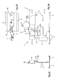
- the main runner has been given the reference numeral 1 and the cross runner the reference numeral 2.
- the runners 1, 2 each comprise an upright longitudinally extending web 3 having flanges 4 extending in opposite sideways directions at its lower end for supporting edges of ceiling panels 5 upon, and having a longitudinally extending hollow profile 6 at its upper end for providing strength.
- the cross runner 2 comprises a coupling hook 7 which can be hooked into a slit 8 provided in the main runner 1.
- fig. 1 the situation is shown in which a cross runner 2 has already been hooked onto the main runner 1 from one side, whereas another cross runner 2 still needs to be hooked onto this main runner 1 from the other side. Both cross runners 2 hook into the same slit 8 of the main runner 1.
- the cross runner 2 further comprises a heat expansion nose section 10.
- the nose section 10 comprises a free end part 11 of the hollow profile 6 which at its lower side is bounded by a cut 12.
- the cut 12 has a first part 12a extending in the longitudinal direction of the cross runner 2 through its web 3, and a second part 12b extending in a slanted upward direction of approximately 75 degrees through both the web 3 and partly into the hollow profile 6.
- the nose section 10 is provided with a concavely shaped longitudinal impression 15.
- the impression 15 extends over the entire height of the hollow profile 6, including its top face 16, and substantially in the same slanting direction as the second part 12b of the cut.
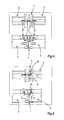
- the impression 15 preferably has been made by locally impressing the hollow profile 6 at the location of the folding line 17 by exerting pressure from one side upon the hollow profile 6 over its entire height.
- the pressure causes opposite wall parts of the hollow profile 6 to be compressed towards one another over the entire height of the hollow profile 6.
- the pressure causes the top face of the hollow profile 6 to be deformed upwardly at the location of the impression 15. Because the impression 15 is made by exerting pressure from one side upon the hollow profile 6, the compressed wall parts have come to lie eccentrically from the center of the cross runner 2 ( fig. 3b ), in particular past the center face of the web 3.
- the cut 12 can be obtained by performing a punching operation on the cross runner 2.
- the pressure for making the impression 15 is exerted in a direction opposite to a punching direction for forming the cut 12 and/or for (de-)forming other parts of the cross runner 2. This might provide for counter forces during manufacturing and/or might pre-bend the nose section 10 slightly in a desired bending direction.
- the hook 7 together with the slit 8 are constructed such that they have the freedom to slide in the longitudinal direction of the cross runner 2, the cross runner 2 is free to expand and/or move in its longitudinal direction with respect to the main runner 1 as soon as the nose section 10 has cleared the way and no longer fully abuts with its front face against the main runner 1. Since the hook 7 also has the freedom to move somewhat upwards with respect to the slit 8, the flanges 4 of the cross runner 2 have the freedom to slide over the facing flange 4' of the main runner 1. The fact that the impression 15, the second part 12b of the cut and thus the folding line 17 are positioned at an angle with respect to the horizontal aids in this upward movement, because the nose section 10 also moves upward somewhat during its sideways bending movement.
- the second part 12b of the cut goes through a lower part of the impression 15, in particular through at least the lower half of the impression 15.
- This has the advantage of limiting the bending force needed for the bending movement.
- the length of the second part 12b of the cut going through the lower part of the impression 15, may be altered in dependency of the shape, height, material, thickness, etc. of the hollow profile 6, that is to say of the original bending resistance of the hollow profile 6 which possibly needs to be limited.
- the cross runner 2 can be made in several ways, but preferably is roll-formed out of a strip of steel material. After this roll-forming step, the punching operations may be performed for forming the cuts, the impressions, the hook, etc.
- the dimensions of the various parts may be different and/or the runners may be manufactured out of other materials and/or may have differently shaped webs, flanges and/or hollow profiles.
- other kinds of coupling means are possible between the main runner and the cross runners.
- the impressions and the cuts may also be achieved in another way.
- the cuts may also be formed by cut-outs. Also it is possible for the cut to only extend in the longitudinal direction of the cross runner, and not to also partially extend in the direction of the impression.
- the invention provides a user-friendly ceiling frame which is both easy to handle during mounting and stable and reliable during use.
Landscapes
- Engineering & Computer Science (AREA)
- Architecture (AREA)
- Physics & Mathematics (AREA)
- Electromagnetism (AREA)
- Civil Engineering (AREA)
- Structural Engineering (AREA)
- Building Environments (AREA)
- Residential Or Office Buildings (AREA)
- Body Structure For Vehicles (AREA)
- Bending Of Plates, Rods, And Pipes (AREA)
Priority Applications (4)
| Application Number | Priority Date | Filing Date | Title |
|---|---|---|---|
| EP08075069A EP2085530A1 (en) | 2008-01-29 | 2008-01-29 | Ceiling frame for holding ceiling panels having a cross runner with a locally impressed nose section |
| EP09151424.0A EP2085531B1 (en) | 2008-01-29 | 2009-01-27 | Cross runner for use in a ceiling frame with a locally impressed nose section |
| ES09151424.0T ES2537968T3 (es) | 2008-01-29 | 2009-01-27 | Riel transversal para su uso en una estructura de techo con una sección saliente estampada localmente |
| PL09151424T PL2085531T3 (pl) | 2008-01-29 | 2009-01-27 | Profil poprzeczny do zastosowania w ramie sufitowej z miejscowo zagłębionym segmentem głowicowym |
Applications Claiming Priority (1)
| Application Number | Priority Date | Filing Date | Title |
|---|---|---|---|
| EP08075069A EP2085530A1 (en) | 2008-01-29 | 2008-01-29 | Ceiling frame for holding ceiling panels having a cross runner with a locally impressed nose section |
Publications (1)
| Publication Number | Publication Date |
|---|---|
| EP2085530A1 true EP2085530A1 (en) | 2009-08-05 |
Family
ID=39563589
Family Applications (2)
| Application Number | Title | Priority Date | Filing Date |
|---|---|---|---|
| EP08075069A Withdrawn EP2085530A1 (en) | 2008-01-29 | 2008-01-29 | Ceiling frame for holding ceiling panels having a cross runner with a locally impressed nose section |
| EP09151424.0A Active EP2085531B1 (en) | 2008-01-29 | 2009-01-27 | Cross runner for use in a ceiling frame with a locally impressed nose section |
Family Applications After (1)
| Application Number | Title | Priority Date | Filing Date |
|---|---|---|---|
| EP09151424.0A Active EP2085531B1 (en) | 2008-01-29 | 2009-01-27 | Cross runner for use in a ceiling frame with a locally impressed nose section |
Country Status (3)
| Country | Link |
|---|---|
| EP (2) | EP2085530A1 (pl) |
| ES (1) | ES2537968T3 (pl) |
| PL (1) | PL2085531T3 (pl) |
Families Citing this family (3)
| Publication number | Priority date | Publication date | Assignee | Title |
|---|---|---|---|---|
| RU2658927C1 (ru) * | 2017-09-21 | 2018-06-26 | Александр Васильевич Гущин | Универсальная декоративная подвесная рамочная потолочная и стеновая система |
| RU2663519C1 (ru) * | 2017-12-04 | 2018-08-07 | Александр Васильевич Гущин | Универсальная декоративная подвесная рамочная потолочная система на гибких подвесах |
| RU2694635C1 (ru) * | 2018-08-09 | 2019-07-16 | Александр Васильевич Гущин | Усовершенствованная универсальная подвесная рамочная потолочная и стеновая система из панелей с гибким декоративным материалом и способ его крепления |
Citations (7)
| Publication number | Priority date | Publication date | Assignee | Title |
|---|---|---|---|---|
| US3965631A (en) * | 1974-08-01 | 1976-06-29 | Roblin Hope's Industries, Inc. | Fire rated grid-member with controlled expansion means |
| US4106878A (en) * | 1977-02-04 | 1978-08-15 | National Rolling Mills Company | Fire-rated ceiling grid cross joint |
| US4364686A (en) * | 1980-11-17 | 1982-12-21 | Lok Products Company | Locking device for grid system |
| GB2164074A (en) * | 1984-09-06 | 1986-03-12 | Donn Inc | Ceiling grid runner accommodating thermal expansion due to fire |
| US4713919A (en) * | 1986-09-05 | 1987-12-22 | National Rolling Mills Inc. | Laser welded ceiling grid members |
| EP1167649A2 (en) * | 2000-07-01 | 2002-01-02 | Worthington Armstrong Venture | Compression relief section |
| EP1703034A1 (en) | 2005-03-18 | 2006-09-20 | Chicago Metallic Continental | Ceiling suspension system |
Family Cites Families (1)
| Publication number | Priority date | Publication date | Assignee | Title |
|---|---|---|---|---|
| US3496690A (en) * | 1967-04-17 | 1970-02-24 | Chicago Metallic Sash Co | Main runner part |
-
2008
- 2008-01-29 EP EP08075069A patent/EP2085530A1/en not_active Withdrawn
-
2009
- 2009-01-27 EP EP09151424.0A patent/EP2085531B1/en active Active
- 2009-01-27 ES ES09151424.0T patent/ES2537968T3/es active Active
- 2009-01-27 PL PL09151424T patent/PL2085531T3/pl unknown
Patent Citations (8)
| Publication number | Priority date | Publication date | Assignee | Title |
|---|---|---|---|---|
| US3965631A (en) * | 1974-08-01 | 1976-06-29 | Roblin Hope's Industries, Inc. | Fire rated grid-member with controlled expansion means |
| US3965631B1 (pl) * | 1974-08-01 | 1987-03-31 | ||
| US4106878A (en) * | 1977-02-04 | 1978-08-15 | National Rolling Mills Company | Fire-rated ceiling grid cross joint |
| US4364686A (en) * | 1980-11-17 | 1982-12-21 | Lok Products Company | Locking device for grid system |
| GB2164074A (en) * | 1984-09-06 | 1986-03-12 | Donn Inc | Ceiling grid runner accommodating thermal expansion due to fire |
| US4713919A (en) * | 1986-09-05 | 1987-12-22 | National Rolling Mills Inc. | Laser welded ceiling grid members |
| EP1167649A2 (en) * | 2000-07-01 | 2002-01-02 | Worthington Armstrong Venture | Compression relief section |
| EP1703034A1 (en) | 2005-03-18 | 2006-09-20 | Chicago Metallic Continental | Ceiling suspension system |
Also Published As
| Publication number | Publication date |
|---|---|
| EP2085531B1 (en) | 2015-03-18 |
| PL2085531T3 (pl) | 2015-08-31 |
| ES2537968T3 (es) | 2015-06-16 |
| EP2085531A2 (en) | 2009-08-05 |
| EP2085531A3 (en) | 2013-09-04 |
Similar Documents
| Publication | Publication Date | Title |
|---|---|---|
| EP1978175B1 (en) | Beam for a drywall ceiling soffit | |
| US11193268B2 (en) | Joist hanger | |
| US9091078B2 (en) | Attachment device for sheet type construction siding | |
| US6484980B2 (en) | Field bendable tab for electrical box support | |
| CN104350219B (zh) | 格栅龙骨的周边装饰夹子 | |
| JP6427163B2 (ja) | 涙滴状切込み及びオフセットした切込み付きブリッジコネクタ | |
| DK171516B1 (da) | Fremgangsmåde til fremstilling af længdeindstillelig stangkobling | |
| EP2956594B1 (en) | Support metal structure of a false ceiling | |
| CN101351602A (zh) | 用于吊顶的网格t形件 | |
| EP2753768B1 (en) | Cross runner connector | |
| WO2011103043A1 (en) | Hurricane tie fastener and method of use | |
| EP2085531B1 (en) | Cross runner for use in a ceiling frame with a locally impressed nose section | |
| WO2015091244A1 (de) | Schubladenwandelement | |
| CN104937186A (zh) | 用于周边装饰的夹子 | |
| US8590160B2 (en) | Grid runner cap anchoring lance | |
| EP2398605B1 (en) | Method for twisting hollow bars | |
| TW514693B (en) | Metal roof truss | |
| ITFI940015A1 (it) | "una traversa in profilato tubolare per il collegamento dei montanti in scaffalature metalliche" | |
| BE1023594B1 (nl) | Metalen dak- en/of gevelbedekking en werkwijze voor het bedekken van een dak en/of gevel | |
| EP4382224A1 (en) | Improved method for manufacturing ventilation grilles | |
| KR20240002009U (ko) | 롤 블라인드 스냅의 전후 조절설치용 브래킷 조립체 | |
| JP3071246U (ja) | 雪辷り止めアングル用金具 | |
| JP3697119B2 (ja) | 建築用板の接続構造 | |
| EP1412594A2 (en) | Bendale sections with one or more fixable sliding walls | |
| JP2008285813A (ja) | 天井板用吊持杆の連結機構 |
Legal Events
| Date | Code | Title | Description |
|---|---|---|---|
| PUAI | Public reference made under article 153(3) epc to a published international application that has entered the european phase |
Free format text: ORIGINAL CODE: 0009012 |
|
| AK | Designated contracting states |
Kind code of ref document: A1 Designated state(s): AT BE BG CH CY CZ DE DK EE ES FI FR GB GR HR HU IE IS IT LI LT LU LV MC MT NL NO PL PT RO SE SI SK TR |
|
| AX | Request for extension of the european patent |
Extension state: AL BA MK RS |
|
| AKX | Designation fees paid | ||
| REG | Reference to a national code |
Ref country code: DE Ref legal event code: 8566 |
|
| STAA | Information on the status of an ep patent application or granted ep patent |
Free format text: STATUS: THE APPLICATION IS DEEMED TO BE WITHDRAWN |
|
| 18D | Application deemed to be withdrawn |
Effective date: 20100206 |