EP2085564A2 - Dispositif d'entraînement doté d'un accouplement à patinage ou d'un frein - Google Patents
Dispositif d'entraînement doté d'un accouplement à patinage ou d'un frein Download PDFInfo
- Publication number
- EP2085564A2 EP2085564A2 EP09001269A EP09001269A EP2085564A2 EP 2085564 A2 EP2085564 A2 EP 2085564A2 EP 09001269 A EP09001269 A EP 09001269A EP 09001269 A EP09001269 A EP 09001269A EP 2085564 A2 EP2085564 A2 EP 2085564A2
- Authority
- EP
- European Patent Office
- Prior art keywords
- drive device
- rotation
- shaft
- der
- drive
- Prior art date
- Legal status (The legal status is an assumption and is not a legal conclusion. Google has not performed a legal analysis and makes no representation as to the accuracy of the status listed.)
- Withdrawn
Links
- 238000004804 winding Methods 0.000 claims description 12
- 230000000694 effects Effects 0.000 description 2
- 230000002093 peripheral effect Effects 0.000 description 2
- 235000010678 Paulownia tomentosa Nutrition 0.000 description 1
- 240000002834 Paulownia tomentosa Species 0.000 description 1
- 230000006978 adaptation Effects 0.000 description 1
- 230000005540 biological transmission Effects 0.000 description 1
- 238000009434 installation Methods 0.000 description 1
- 239000010985 leather Substances 0.000 description 1
- 239000002184 metal Substances 0.000 description 1
Images




Classifications
-
- E—FIXED CONSTRUCTIONS
- E06—DOORS, WINDOWS, SHUTTERS, OR ROLLER BLINDS IN GENERAL; LADDERS
- E06B—FIXED OR MOVABLE CLOSURES FOR OPENINGS IN BUILDINGS, VEHICLES, FENCES OR LIKE ENCLOSURES IN GENERAL, e.g. DOORS, WINDOWS, BLINDS, GATES
- E06B9/00—Screening or protective devices for wall or similar openings, with or without operating or securing mechanisms; Closures of similar construction
- E06B9/56—Operating, guiding or securing devices or arrangements for roll-type closures; Spring drums; Tape drums; Counterweighting arrangements therefor
- E06B9/68—Operating devices or mechanisms, e.g. with electric drive
-
- E—FIXED CONSTRUCTIONS
- E06—DOORS, WINDOWS, SHUTTERS, OR ROLLER BLINDS IN GENERAL; LADDERS
- E06B—FIXED OR MOVABLE CLOSURES FOR OPENINGS IN BUILDINGS, VEHICLES, FENCES OR LIKE ENCLOSURES IN GENERAL, e.g. DOORS, WINDOWS, BLINDS, GATES
- E06B9/00—Screening or protective devices for wall or similar openings, with or without operating or securing mechanisms; Closures of similar construction
- E06B9/56—Operating, guiding or securing devices or arrangements for roll-type closures; Spring drums; Tape drums; Counterweighting arrangements therefor
- E06B9/80—Safety measures against dropping or unauthorised opening; Braking or immobilising devices; Devices for limiting unrolling
-
- F—MECHANICAL ENGINEERING; LIGHTING; HEATING; WEAPONS; BLASTING
- F16—ENGINEERING ELEMENTS AND UNITS; GENERAL MEASURES FOR PRODUCING AND MAINTAINING EFFECTIVE FUNCTIONING OF MACHINES OR INSTALLATIONS; THERMAL INSULATION IN GENERAL
- F16D—COUPLINGS FOR TRANSMITTING ROTATION; CLUTCHES; BRAKES
- F16D41/00—Freewheels or freewheel clutches
- F16D41/20—Freewheels or freewheel clutches with expandable or contractable clamping ring or band
- F16D41/206—Freewheels or freewheel clutches with expandable or contractable clamping ring or band having axially adjacent coils, e.g. helical wrap-springs
-
- F—MECHANICAL ENGINEERING; LIGHTING; HEATING; WEAPONS; BLASTING
- F16—ENGINEERING ELEMENTS AND UNITS; GENERAL MEASURES FOR PRODUCING AND MAINTAINING EFFECTIVE FUNCTIONING OF MACHINES OR INSTALLATIONS; THERMAL INSULATION IN GENERAL
- F16D—COUPLINGS FOR TRANSMITTING ROTATION; CLUTCHES; BRAKES
- F16D7/00—Slip couplings, e.g. slipping on overload, for absorbing shock
- F16D7/02—Slip couplings, e.g. slipping on overload, for absorbing shock of the friction type
- F16D7/022—Slip couplings, e.g. slipping on overload, for absorbing shock of the friction type with a helical band or equivalent member co-operating with a cylindrical torque limiting coupling surface
-
- E—FIXED CONSTRUCTIONS
- E05—LOCKS; KEYS; WINDOW OR DOOR FITTINGS; SAFES
- E05Y—INDEXING SCHEME ASSOCIATED WITH SUBCLASSES E05D AND E05F, RELATING TO CONSTRUCTION ELEMENTS, ELECTRIC CONTROL, POWER SUPPLY, POWER SIGNAL OR TRANSMISSION, USER INTERFACES, MOUNTING OR COUPLING, DETAILS, ACCESSORIES, AUXILIARY OPERATIONS NOT OTHERWISE PROVIDED FOR, APPLICATION THEREOF
- E05Y2201/00—Constructional elements; Accessories therefor
- E05Y2201/40—Motors; Magnets; Springs; Weights; Accessories therefor
- E05Y2201/47—Springs
- E05Y2201/49—Wrap springs
-
- E—FIXED CONSTRUCTIONS
- E05—LOCKS; KEYS; WINDOW OR DOOR FITTINGS; SAFES
- E05Y—INDEXING SCHEME ASSOCIATED WITH SUBCLASSES E05D AND E05F, RELATING TO CONSTRUCTION ELEMENTS, ELECTRIC CONTROL, POWER SUPPLY, POWER SIGNAL OR TRANSMISSION, USER INTERFACES, MOUNTING OR COUPLING, DETAILS, ACCESSORIES, AUXILIARY OPERATIONS NOT OTHERWISE PROVIDED FOR, APPLICATION THEREOF
- E05Y2800/00—Details, accessories and auxiliary operations not otherwise provided for
- E05Y2800/20—Combinations of elements
- E05Y2800/21—Combinations of elements of identical elements, e.g. of identical compression springs
-
- E—FIXED CONSTRUCTIONS
- E05—LOCKS; KEYS; WINDOW OR DOOR FITTINGS; SAFES
- E05Y—INDEXING SCHEME ASSOCIATED WITH SUBCLASSES E05D AND E05F, RELATING TO CONSTRUCTION ELEMENTS, ELECTRIC CONTROL, POWER SUPPLY, POWER SIGNAL OR TRANSMISSION, USER INTERFACES, MOUNTING OR COUPLING, DETAILS, ACCESSORIES, AUXILIARY OPERATIONS NOT OTHERWISE PROVIDED FOR, APPLICATION THEREOF
- E05Y2900/00—Application of doors, windows, wings or fittings thereof
Definitions
- the invention relates to a drive device with a slip clutch or brake according to the preamble of claim 1.
- Such a device for a slip clutch is preferably used on the output side of the drive and drive side of the winding shaft of awning, shutters, blinds or the like.
- the slip clutch consists of two part clutches, which act in two opposite directions of rotation.
- the partial clutches can have release moments which are designed differently for both directions of rotation.
- the partial clutches each work with a gear designed as a ring gear, each associated with at least one centrally arranged spring element, which is designed as a metal strip. Also in these devices, the release moments are chosen such that the slip clutch serves as overload protection in both directions of rotation.
- the object of the invention is to avoid this explained false effect in a device referred to in the preamble of claim 1.
- the coil springs acting in both directions exert different braking torques. This results in an adaptation to the forces acting on the drive device.
- a plurality of coil springs are provided for one direction of rotation or for both directions of rotation. Thus, the required braking force with coil springs same or different type can be easily adjusted.
- the claimed slip clutch can also be used in a transmission, wherein the drive unit is a driven shaft and the output unit is a worm.
- Another application would be housed in a linkage slip clutch, a shaft with a drill pipe via the coil springs can be coupled, the spring ends are mounted in the drill pipe.
- the invention can be applied to a brake having a continuous drive from a worm, on whose shaft the coil springs are arranged, whose ends are mounted in a control housing.
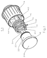
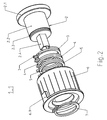
- a first embodiment of a drive device 1.1 for the winding shaft of a shutter, a blind or an awning is in the FIGS. 1 to 12 shown.
- the drive device 1.1 consists of a drive unit which is designed as a driver shaft 2, three coil springs acting as drag springs 3, 4 and 5, an output unit which is designed as a tube driver 6, and a securing ring. 7
- the driving shaft 2 includes (see also the Figures 3-5 ) successively a disc 2.1, a shaft 2.2, arranged at the end of the shaft 2.2 annular groove 2.3 and a square piece 2.4.
- the drive shaft 2 may be connected in a manner not shown with a hand crank or a motor.
- Each coil spring 3-5 (see also the Figures 6-8 ) comprises almost two turns and carries at its ends bent end pieces, such as the end pieces 3.1 and 3.2 of the coil spring 3.
- the coil springs - 4 +5 have the same installation position, while the coil spring 3 180 ° is mounted turned around the spring end 3.1.
- the coil springs 3-5 are preferably pushed under bias on the shaft 2.2, wherein they touch the peripheral surface of the shaft 2.2.
- each coil spring with different turns / sense of winding and / or only with a bent end piece such as the end pieces 3.1 and 3.2 be configured.
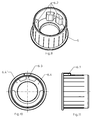
- the pipe driver 6 (see also the Figures 9-12 ) is provided on the outer circumference with a locking piece 6.1, which engages when plugging the Rohrmit mecanics in a winding shaft, not shown, for the curtain, so that the Rohrmit legislative 6 is radially connected to the winding shaft.
- the pipe driver 6 has on its inner circumference a plurality of circular projections 6.2, are formed by the grooves 6.3, 6.4 and 6.4 '. In these grooves engage the end pieces (for example, 3.1, 3.2) of the coil springs 3-5.
- the coil springs 3-5 brake in one direction of rotation and slip through after a first torque X is overcome. This torque X arises from the sum of the closing moments of the springs 4 + 5 plus the opening moment of the spring 3.
- the coil springs slow down 3-5 and slip through after a second torque Y is overcome.
- This moment Y arises from the sum of the opening torques of the springs 4 + 5 plus the closing moment of the spring 3.
- the first torque and the second torque can be dimensioned differently.
- the driver shaft 2 is secured in the pipe driver 6 by the securing ring 7, which engages in the annular groove 2.3.
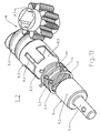
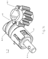
- a second embodiment of the drive device 1.2 is in the Figures 13 . 14 shown.
- the drive device 1.2 from a drive unit 8 in the form of a worm gear, which consists of a gear 8.1, a screw 8.2, in which engages the gear 8.1, and connected to the screw 8.2 tubular housing 8.3, from three acting as drag springs coil springs 3, 4 and 5 and formed from an output unit 9, which includes an output shaft 9.1 and a cylinder 9.2 connected thereto.
- the coil springs 3-5 are preferably biased onto the shaft 9.2, touching the peripheral surface of the shaft 9.2.
- the design and dimensioning of the coil springs correspond to the first embodiment.
- the tubular housing 8.3 has outwardly open, axially parallel slots 8.4, 8.5 and 8.5 ', in which again engage the end pieces (for example 3.1, 3.2 of the coil springs 3-5).
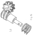
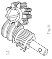
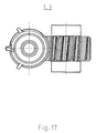
- FIGS. 15 and 16 a similar third embodiment for a brake drive device and a similar fourth embodiment of a linkage are shown.
Landscapes
- Engineering & Computer Science (AREA)
- General Engineering & Computer Science (AREA)
- Structural Engineering (AREA)
- Mechanical Engineering (AREA)
- Architecture (AREA)
- Civil Engineering (AREA)
- Operating, Guiding And Securing Of Roll- Type Closing Members (AREA)
Applications Claiming Priority (1)
| Application Number | Priority Date | Filing Date | Title |
|---|---|---|---|
| DE102008006805 | 2008-01-30 |
Publications (2)
| Publication Number | Publication Date |
|---|---|
| EP2085564A2 true EP2085564A2 (fr) | 2009-08-05 |
| EP2085564A3 EP2085564A3 (fr) | 2013-05-15 |
Family
ID=40600288
Family Applications (1)
| Application Number | Title | Priority Date | Filing Date |
|---|---|---|---|
| EP09001269.1A Withdrawn EP2085564A3 (fr) | 2008-01-30 | 2009-01-30 | Dispositif d'entraînement doté d'un accouplement à patinage ou d'un frein |
Country Status (1)
| Country | Link |
|---|---|
| EP (1) | EP2085564A3 (fr) |
Cited By (7)
| Publication number | Priority date | Publication date | Assignee | Title |
|---|---|---|---|---|
| WO2011018223A3 (fr) * | 2009-08-13 | 2011-09-15 | Gerhard Geiger Gmbh & Co. | Mécanisme de transmission |
| US20130220044A1 (en) * | 2011-11-25 | 2013-08-29 | Yu-Che Wen | Slat controller of window blind |
| US20160369558A1 (en) * | 2015-06-19 | 2016-12-22 | Lutron Electronics Co., Inc. | Variable resistance brake for use with a roller tube of a window treatment |
| DE102019131220A1 (de) * | 2019-10-02 | 2021-04-08 | Liebherr-Hausgeräte Lienz Gmbh | Rutschkupplung |
| DE102021130103A1 (de) | 2021-11-18 | 2023-05-25 | Grass Gmbh | Antriebsvorrichtung mit einem elektrischen Motor zum Bewegen eines beweglichen Möbelteils relativ zu einem Möblekorpus |
| US20240369108A1 (en) * | 2018-07-24 | 2024-11-07 | Borgwarner Inc. | Torque limiting coupler for an electric motor shaft |
| US12528410B2 (en) * | 2022-04-13 | 2026-01-20 | Motherson Innovations Company Limited | Clutch gear, actuator, rear view device and vehicle |
Citations (6)
| Publication number | Priority date | Publication date | Assignee | Title |
|---|---|---|---|---|
| DE3726715A1 (de) | 1986-08-13 | 1988-02-18 | Planya Ag | Einrichtung mit einem rafflamellenstore |
| EP0503161A2 (fr) | 1991-03-09 | 1992-09-16 | V. Kann Rasmussen Industri A/S | Arbre d'enroulement avec accouplement à glissement |
| EP0813646A1 (fr) | 1995-03-06 | 1997-12-29 | V. Kann Rasmussen Industri A/S | Dispositif de commande destine a un agencement de stores |
| WO1999025946A1 (fr) | 1997-11-18 | 1999-05-27 | Ren Judkins | Frein a deblocage pour stores et autres couvre-fenetres |
| DE20102734U1 (de) | 2001-02-16 | 2001-09-06 | Bernhard Böckner GmbH & Co.KG, Herstellungs- und Vertriebsgesellschaft, 35463 Fernwald | Vorrichtung zum Antrieb von verstellbaren Jalousien |
| EP1686231A1 (fr) | 2005-01-14 | 2006-08-02 | Griesser Holding AG | Dispositif de prévention de dommages à des volets |
Family Cites Families (2)
| Publication number | Priority date | Publication date | Assignee | Title |
|---|---|---|---|---|
| JPS58191327A (ja) * | 1982-05-04 | 1983-11-08 | Aisin Seiki Co Ltd | スプリングカツプラ装置 |
| DE202007007502U1 (de) * | 2006-06-06 | 2007-09-06 | Gerhard Geiger Gmbh & Co. | Bremse mit Überlastkupplung für Untersetzungsgetriebe |
-
2009
- 2009-01-30 EP EP09001269.1A patent/EP2085564A3/fr not_active Withdrawn
Patent Citations (7)
| Publication number | Priority date | Publication date | Assignee | Title |
|---|---|---|---|---|
| DE3726715A1 (de) | 1986-08-13 | 1988-02-18 | Planya Ag | Einrichtung mit einem rafflamellenstore |
| EP0503161A2 (fr) | 1991-03-09 | 1992-09-16 | V. Kann Rasmussen Industri A/S | Arbre d'enroulement avec accouplement à glissement |
| DE4107611A1 (de) | 1991-03-09 | 1992-09-17 | Rasmussen Kann Ind As | Wickelwelle mit rutschkupplung |
| EP0813646A1 (fr) | 1995-03-06 | 1997-12-29 | V. Kann Rasmussen Industri A/S | Dispositif de commande destine a un agencement de stores |
| WO1999025946A1 (fr) | 1997-11-18 | 1999-05-27 | Ren Judkins | Frein a deblocage pour stores et autres couvre-fenetres |
| DE20102734U1 (de) | 2001-02-16 | 2001-09-06 | Bernhard Böckner GmbH & Co.KG, Herstellungs- und Vertriebsgesellschaft, 35463 Fernwald | Vorrichtung zum Antrieb von verstellbaren Jalousien |
| EP1686231A1 (fr) | 2005-01-14 | 2006-08-02 | Griesser Holding AG | Dispositif de prévention de dommages à des volets |
Cited By (9)
| Publication number | Priority date | Publication date | Assignee | Title |
|---|---|---|---|---|
| WO2011018223A3 (fr) * | 2009-08-13 | 2011-09-15 | Gerhard Geiger Gmbh & Co. | Mécanisme de transmission |
| US20130220044A1 (en) * | 2011-11-25 | 2013-08-29 | Yu-Che Wen | Slat controller of window blind |
| US8910696B2 (en) * | 2011-11-25 | 2014-12-16 | Nien Made Enterprise Co., Ltd. | Slat controller of window blind |
| US20160369558A1 (en) * | 2015-06-19 | 2016-12-22 | Lutron Electronics Co., Inc. | Variable resistance brake for use with a roller tube of a window treatment |
| US20240369108A1 (en) * | 2018-07-24 | 2024-11-07 | Borgwarner Inc. | Torque limiting coupler for an electric motor shaft |
| US12560206B2 (en) * | 2018-07-24 | 2026-02-24 | Borgwarner Inc. | Torque limiting coupler for an electric motor shaft |
| DE102019131220A1 (de) * | 2019-10-02 | 2021-04-08 | Liebherr-Hausgeräte Lienz Gmbh | Rutschkupplung |
| DE102021130103A1 (de) | 2021-11-18 | 2023-05-25 | Grass Gmbh | Antriebsvorrichtung mit einem elektrischen Motor zum Bewegen eines beweglichen Möbelteils relativ zu einem Möblekorpus |
| US12528410B2 (en) * | 2022-04-13 | 2026-01-20 | Motherson Innovations Company Limited | Clutch gear, actuator, rear view device and vehicle |
Also Published As
| Publication number | Publication date |
|---|---|
| EP2085564A3 (fr) | 2013-05-15 |
Similar Documents
| Publication | Publication Date | Title |
|---|---|---|
| DE69908866T2 (de) | Wickelvorrichtung | |
| EP1921246B1 (fr) | Dispositif de butée pour le mouvement d'ouverture et de fermeture d'une installation d'obscurcissement | |
| DE102015217164B4 (de) | Baugruppe mit einer Reibeinrichtung | |
| DE2913887A1 (de) | Lamellenjalousie mit vertikalen lamellen | |
| WO2012163825A1 (fr) | Arbre pourvu d'un palier | |
| DE102015220920B4 (de) | Baugruppe mit einer Reibeinrichtung | |
| DE10337629A1 (de) | Antrieb | |
| DE2913885A1 (de) | Lamellenjalousie mit senkrecht angeordneten lamellen | |
| DE102006042100B3 (de) | Antriebseinrichtung | |
| DE102009036872A1 (de) | Türeinheit | |
| DE102007051741A1 (de) | Schiebemuffe zum Schalten von Gangstufen eines Schaltgetriebes | |
| DE3420789A1 (de) | Antriebseinheit | |
| EP2314824B1 (fr) | Moteur tubulaire pour un dispositif d'obscurcissement ou analogue | |
| DE3306407A1 (de) | Antriebsvorrichtung fuer lamellenvorhaenge | |
| EP2565364A2 (fr) | Adaptateur pour l'arbre entraîné d'un dispositif d'entraînement tubulaire pour enrouler et dérouler un dispositif d'assombrissement, en particulier un store ou analogue | |
| DE102019111222A1 (de) | Luftleitvorrichtung mit Bremseinrichtung | |
| DE2830360A1 (de) | Antriebsvorrichtung fuer rolladen, jalousien, markisen o.dgl. | |
| DE4107611C2 (fr) | ||
| DE102013225361A1 (de) | Aktor zur Betätigung einer Kupplung | |
| DE102018124681A1 (de) | Vorrichtung und Verfahren zum Synchronisieren | |
| EP1898021A2 (fr) | Dispositif de propulsion pour auvents et analogues | |
| DE102016001917A1 (de) | Gurtaufroller | |
| EP1579939A1 (fr) | Outil | |
| DE102006042458B4 (de) | Antriebseinrichtung | |
| DE102008052843B4 (de) | Antriebseinheit für Verstelleinrichtungen in Kraftfahrzeugen |
Legal Events
| Date | Code | Title | Description |
|---|---|---|---|
| PUAI | Public reference made under article 153(3) epc to a published international application that has entered the european phase |
Free format text: ORIGINAL CODE: 0009012 |
|
| AK | Designated contracting states |
Kind code of ref document: A2 Designated state(s): AT BE BG CH CY CZ DE DK EE ES FI FR GB GR HR HU IE IS IT LI LT LU LV MC MK MT NL NO PL PT RO SE SI SK TR |
|
| AX | Request for extension of the european patent |
Extension state: AL BA RS |
|
| PUAL | Search report despatched |
Free format text: ORIGINAL CODE: 0009013 |
|
| AK | Designated contracting states |
Kind code of ref document: A3 Designated state(s): AT BE BG CH CY CZ DE DK EE ES FI FR GB GR HR HU IE IS IT LI LT LU LV MC MK MT NL NO PL PT RO SE SI SK TR |
|
| AX | Request for extension of the european patent |
Extension state: AL BA RS |
|
| RIC1 | Information provided on ipc code assigned before grant |
Ipc: F16D 7/02 20060101ALI20130411BHEP Ipc: E06B 9/68 20060101AFI20130411BHEP Ipc: E06B 9/80 20060101ALI20130411BHEP |
|
| AKY | No designation fees paid | ||
| REG | Reference to a national code |
Ref country code: DE Ref legal event code: R108 |
|
| REG | Reference to a national code |
Ref country code: DE Ref legal event code: R108 Effective date: 20140122 |
|
| STAA | Information on the status of an ep patent application or granted ep patent |
Free format text: STATUS: THE APPLICATION IS DEEMED TO BE WITHDRAWN |
|
| 18D | Application deemed to be withdrawn |
Effective date: 20131116 |