EP2085590A2 - Transmission de couple pour moteur d'avion et méthode pour maintenir une réduction de vitesse constante entre deux arbres en rotation - Google Patents
Transmission de couple pour moteur d'avion et méthode pour maintenir une réduction de vitesse constante entre deux arbres en rotation Download PDFInfo
- Publication number
- EP2085590A2 EP2085590A2 EP09250245A EP09250245A EP2085590A2 EP 2085590 A2 EP2085590 A2 EP 2085590A2 EP 09250245 A EP09250245 A EP 09250245A EP 09250245 A EP09250245 A EP 09250245A EP 2085590 A2 EP2085590 A2 EP 2085590A2
- Authority
- EP
- European Patent Office
- Prior art keywords
- engine
- starter
- generator
- ratio
- torque
- Prior art date
- Legal status (The legal status is an assumption and is not a legal conclusion. Google has not performed a legal analysis and makes no representation as to the accuracy of the status listed.)
- Withdrawn
Links
- 230000005540 biological transmission Effects 0.000 title claims abstract description 34
- 238000000034 method Methods 0.000 title claims abstract description 12
- 238000012546 transfer Methods 0.000 claims description 6
- 239000007789 gas Substances 0.000 description 6
- 238000012986 modification Methods 0.000 description 3
- 230000004048 modification Effects 0.000 description 3
- 239000007858 starting material Substances 0.000 description 3
- 239000003570 air Substances 0.000 description 2
- 239000000567 combustion gas Substances 0.000 description 2
- 239000012080 ambient air Substances 0.000 description 1
- 238000004891 communication Methods 0.000 description 1
- 238000010276 construction Methods 0.000 description 1
- 238000013461 design Methods 0.000 description 1
- 238000010586 diagram Methods 0.000 description 1
- 239000000446 fuel Substances 0.000 description 1
- 238000012552 review Methods 0.000 description 1
Images
Classifications
-
- F—MECHANICAL ENGINEERING; LIGHTING; HEATING; WEAPONS; BLASTING
- F02—COMBUSTION ENGINES; HOT-GAS OR COMBUSTION-PRODUCT ENGINE PLANTS
- F02C—GAS-TURBINE PLANTS; AIR INTAKES FOR JET-PROPULSION PLANTS; CONTROLLING FUEL SUPPLY IN AIR-BREATHING JET-PROPULSION PLANTS
- F02C7/00—Features, components parts, details or accessories, not provided for in, or of interest apart form groups F02C1/00 - F02C6/00; Air intakes for jet-propulsion plants
- F02C7/36—Power transmission arrangements between the different shafts of the gas turbine plant, or between the gas-turbine plant and the power user
-
- F—MECHANICAL ENGINEERING; LIGHTING; HEATING; WEAPONS; BLASTING
- F02—COMBUSTION ENGINES; HOT-GAS OR COMBUSTION-PRODUCT ENGINE PLANTS
- F02C—GAS-TURBINE PLANTS; AIR INTAKES FOR JET-PROPULSION PLANTS; CONTROLLING FUEL SUPPLY IN AIR-BREATHING JET-PROPULSION PLANTS
- F02C7/00—Features, components parts, details or accessories, not provided for in, or of interest apart form groups F02C1/00 - F02C6/00; Air intakes for jet-propulsion plants
- F02C7/26—Starting; Ignition
- F02C7/268—Starting drives for the rotor, acting directly on the rotor of the gas turbine to be started
- F02C7/275—Mechanical drives
-
- F—MECHANICAL ENGINEERING; LIGHTING; HEATING; WEAPONS; BLASTING
- F05—INDEXING SCHEMES RELATING TO ENGINES OR PUMPS IN VARIOUS SUBCLASSES OF CLASSES F01-F04
- F05D—INDEXING SCHEME FOR ASPECTS RELATING TO NON-POSITIVE-DISPLACEMENT MACHINES OR ENGINES, GAS-TURBINES OR JET-PROPULSION PLANTS
- F05D2220/00—Application
- F05D2220/70—Application in combination with
- F05D2220/76—Application in combination with an electrical generator
-
- F—MECHANICAL ENGINEERING; LIGHTING; HEATING; WEAPONS; BLASTING
- F05—INDEXING SCHEMES RELATING TO ENGINES OR PUMPS IN VARIOUS SUBCLASSES OF CLASSES F01-F04
- F05D—INDEXING SCHEME FOR ASPECTS RELATING TO NON-POSITIVE-DISPLACEMENT MACHINES OR ENGINES, GAS-TURBINES OR JET-PROPULSION PLANTS
- F05D2260/00—Function
- F05D2260/85—Starting
-
- F—MECHANICAL ENGINEERING; LIGHTING; HEATING; WEAPONS; BLASTING
- F05—INDEXING SCHEMES RELATING TO ENGINES OR PUMPS IN VARIOUS SUBCLASSES OF CLASSES F01-F04
- F05D—INDEXING SCHEME FOR ASPECTS RELATING TO NON-POSITIVE-DISPLACEMENT MACHINES OR ENGINES, GAS-TURBINES OR JET-PROPULSION PLANTS
- F05D2270/00—Control
- F05D2270/01—Purpose of the control system
- F05D2270/06—Purpose of the control system to match engine to driven device
- F05D2270/061—Purpose of the control system to match engine to driven device in particular the electrical frequency of driven generator
-
- Y—GENERAL TAGGING OF NEW TECHNOLOGICAL DEVELOPMENTS; GENERAL TAGGING OF CROSS-SECTIONAL TECHNOLOGIES SPANNING OVER SEVERAL SECTIONS OF THE IPC; TECHNICAL SUBJECTS COVERED BY FORMER USPC CROSS-REFERENCE ART COLLECTIONS [XRACs] AND DIGESTS
- Y02—TECHNOLOGIES OR APPLICATIONS FOR MITIGATION OR ADAPTATION AGAINST CLIMATE CHANGE
- Y02T—CLIMATE CHANGE MITIGATION TECHNOLOGIES RELATED TO TRANSPORTATION
- Y02T50/00—Aeronautics or air transport
- Y02T50/60—Efficient propulsion technologies, e.g. for aircraft
-
- Y—GENERAL TAGGING OF NEW TECHNOLOGICAL DEVELOPMENTS; GENERAL TAGGING OF CROSS-SECTIONAL TECHNOLOGIES SPANNING OVER SEVERAL SECTIONS OF THE IPC; TECHNICAL SUBJECTS COVERED BY FORMER USPC CROSS-REFERENCE ART COLLECTIONS [XRACs] AND DIGESTS
- Y10—TECHNICAL SUBJECTS COVERED BY FORMER USPC
- Y10T—TECHNICAL SUBJECTS COVERED BY FORMER US CLASSIFICATION
- Y10T74/00—Machine element or mechanism
- Y10T74/19—Gearing
- Y10T74/19172—Reversal of direction of power flow changes power transmission to alternate path
- Y10T74/19177—Input and output exchange functions
Definitions
- the field of invention generally relates to a torque transmission arrangement and to a method of providing a speed reduction between a starter-generator and an aircraft engine.
- the present concept provides an aircraft engine comprising a starter-generator drivingly connected to a drive shaft through a transmission, the transmission having a first speed reducing transmission ratio when driven by the starter-generator and having a second speed reducing transmission ratio when driven by the drive shaft.
- the present concept provides a bi-directional torque transmission system for use in an aircraft engine, the system comprising: a first input/output shaft; a second input/output shaft; a first set of continuously-meshed gears interposed between the first and the second input/output shaft; a second set of continuously-meshed gears interposed between the first and the second input/output shaft; a first one-way clutch associated with the first gear set, the first one-way clutch drivingly connecting together the first input/output shaft, the first gear set and the second input/output shaft upon transfer of a torque from the first input/output shaft to the second input/output shaft; and a second one-way clutch associated with the second gear set, the second one-way clutch drivingly connecting together the second input/output shaft, the second gear set and the first input/output shaft upon transfer of a torque from the second input/output shaft to the first input/output shaft.
- the present concept provides a system for transferring torque in a gas turbine engine between a starter-generator and an engine spool shaft between which the system is connected, the system comprising a first speed-reduction transmission mode in which torque is transmitted from the starter-generator to the engine spool shaft, and a second speed-reduction torque transmission mode in which torque is transmitted from the engine spool shaft to the starter-generator.
- the present concept provides a method of providing a constant speed reduction between two rotating parts in an aircraft engine, the method comprising: generating a starting torque during engine start and automatically creating a first unidirectional torque-transmission engagement between the two parts; once the engine runs on its own, interrupting the starting torque and automatically disengaging the first unidirectional torque-transmission engagement; and generating a driving torque with the running engine and automatically creating a second unidirectional torque-transmission engagement by which at least some of the driving torque is transmitted between the two parts in a direction opposite that of the starting torque.
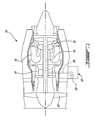
- Fig. 1 illustrates an example of a gas turbine engine 10 generally comprising in serial flow communication a fan 12 through which ambient air is propelled, a multistage compressor 14 for pressurizing the air, a combustor 16 in which the compressed air is mixed with fuel and ignited for generating an annular stream of hot combustion gases, and a turbine section 18 for extracting energy from the combustion gases.
- a high pressure compressor-turbine shaft 25 is connected by a transmission 20 (presented rather schematically in Fig. 1 ) to an electric starter-generator 23, located in this example on an accessory gearbox (AGB) 19.
- AGB accessory gearbox
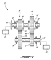
- Fig. 2 shows an example of a torque transmission system 20 as improved.
- This system 20 is designed to be used in the gas turbine engine 10. It comprises a first input/output shaft 22 and a second input/output shaft 24. Both shafts 22, 24 are parallel and juxtaposed in this example, other configurations being also possible. Each shaft 22, 24 is supported by a corresponding set of bearings 26, 28, 30, 32.
- the first input/output shaft 22 can be connected to the starter-generator 23 of the engine, while the second input/output shaft 24 can be connected to a drive shaft, for instance the engine spool shaft 25.
- These connections can be direct or indirect, using for instance including a tower shaft or other kinds of mechanical links to carry the rotational movement.
- the illustrated system 20 comprises a first set 34 of continuously-meshed gears interposed between the first and the second input/output shaft 22, 24.
- This first gear set 34 has two gears 36, 38 of different diameters.
- the first smaller gear 36 is coaxially mounted around the first input/output shaft 22 and the second larger gear 38 is coaxially mounted around the second input/output shaft 24.
- the system 20 also comprises a second set 40 of continuously-meshed gears interposed between the first and the second input/output shaft 22, 24.
- This second gear set 40 has two gears 42, 44 of different diameters.
- the first smaller gear 44 is coaxially mounted around the second input/output shaft 24 and the second larger gear 42 is coaxially mounted around the first input/output shaft 22.
- a first one-way clutch 50 associated with the first gear set 34, is provided for drivingly connecting together the first input/output shaft 22, the first gear set 34 and the second input/output shaft 24 upon transfer of a torque from the first input/output shaft 22 toward the second input/output shaft 24.
- a second one-way clutch 52 associated with the second gear set 40, is provided for drivingly connecting together the second input/output shaft 24, the second gear set 40 and the first input/output shaft 22 upon transfer of a torque from the second input/output shaft 24 toward the first input/output shaft 22.
- one of the one-way clutches 50, 52 works in the clockwise direction and the other works in the counter-clockwise direction.
- One-way clutches 50, 52 are activated by a torque provided in one direction from the input side to the output side thereof. They offer no or very little resistance in the opposite direction.
- the first one-way clutch 50 and the second one-way clutch 52 can each include a sprag.
- the sprag clutch 50 associated with the first gear set 34 is coaxially mounted between the first smaller gear 36 and the first input/output shaft 22.
- the sprag clutch 52 associated with the second gear set 40 is coaxially mounted between the second larger gear 42 and the first input/output shaft 22. Mounting one of the sprag clutches 50, 52 or even both of them on the second input/output shaft 24 would have also been possible.
- the system 20 provides a bi-directionally transmission of the torque between the starter-generator 23 to which the first input/output shaft 22 of the system 20 is mechanically connected, and the drive shaft 25 to which the second input/output shaft 24 of the system 20 is mechanically connected.
- the system 20 has a first transmission mode in which torque is transmitted at a constant first speed reducing ratio from the first input/output shaft 22 to the second input/output shaft 24, and a second torque transmission mode in which torque is transmitted at a constant second speed reducing ratio from the second input/output shaft 24 to the first input/output shaft 22.
- Torque is transmitted in the first transmission mode using the first one-way clutch 50 and the second transmission mode uses the second one-way clutch 52 to transmit the torque in the other direction.
- the first and the second speed reducing ratio may be equal or different, depending on the needs. However, using this system 20, a speed reducing ratio is provided in both directions. With the speed reducing ratio, the input shaft rotates faster than the output shaft and the torque at the output shaft is proportionally increased.
- electrical power is sent to the starter-generator 23 during engine start.
- the starter-generator 23 then generates a starting torque. This automatically creates a first unidirectional torque-transmission engagement between the starter-generator 23 and the drive shaft 25 because of the first one-way clutch 50.
- the second one-way clutch 52 is inactive since it is opposite the first one-way clutch 50.
- the present system and method allow the starter-generator to be designed to rotate at a high rotation speed when providing a starting torque while not overrunning when receiving a driving torque from the running engine to generate electrical power.
- the system and the method are not limited for use with a turbofan engine, and may be used with any suitable engine such as other gas turbine engines and even piston engines.
- the starter-generator may be located in the AGB as described, or mounted concentrically with an engine spool shaft, or provided in any other suitable configuration.
- the concept is not strictly limited to use with electric starter-generators, and any suitable starter-generator device(s) may be used.
- the stator-generator can be substituted by a non-electrical device, such as a pneumatic or hydraulic device.
- the transmission need not be mechanical, and may be hydraulic, pneumatic, magnetic, or any suitable transmission.
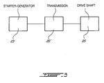
- the speed-reduction ratios of the transmission need not be constant, and a continuously variable transmission (CVT) (see 20' in Fig. 3 ) or other suitable variable transmission may be used.
- CVT continuously variable transmission
- the described transmission is also subject to modification.
- each set of gears can have more than two gears.
- the first and the second set of gears can have a different number of gears.
- the sprag clutch is only one of the possible kinds of one-way clutches and other kinds of one-way clutches can be used as well.
- the first one-way clutch and the second one-way clutch do not need to be identical. As aforesaid, mounting one of the one-way clutches or even both of them on the second input/output shaft instead of the first input/output shaft is possible. Yet, using more than two one-way clutches in the same gear set is possible.
- the input/output shafts can be coaxial.
- the gear arrangement could then be configured as an epicyclical gear arrangement, for instance.
- the expression "drive shaft” must be construed in a broad sense.
- the link between the system and the starter-generator and the shaft can be direct or indirect. For instance, the drive shaft and the system can be mechanically connected together using a tower shaft and a plurality of external gears. Still other modifications which fall within the scope of the present invention will be apparent to those skilled in the art, in light of a review of this disclosure, and such modifications are intended to fall within the scope of the appended claims.
Landscapes
- Engineering & Computer Science (AREA)
- Chemical & Material Sciences (AREA)
- Combustion & Propulsion (AREA)
- Mechanical Engineering (AREA)
- General Engineering & Computer Science (AREA)
- Connection Of Motors, Electrical Generators, Mechanical Devices, And The Like (AREA)
- Structure Of Transmissions (AREA)
Applications Claiming Priority (1)
| Application Number | Priority Date | Filing Date | Title |
|---|---|---|---|
| US12/022,236 US8169100B2 (en) | 2008-01-30 | 2008-01-30 | Torque transmission for an aircraft engine |
Publications (1)
| Publication Number | Publication Date |
|---|---|
| EP2085590A2 true EP2085590A2 (fr) | 2009-08-05 |
Family
ID=40467383
Family Applications (1)
| Application Number | Title | Priority Date | Filing Date |
|---|---|---|---|
| EP09250245A Withdrawn EP2085590A2 (fr) | 2008-01-30 | 2009-01-29 | Transmission de couple pour moteur d'avion et méthode pour maintenir une réduction de vitesse constante entre deux arbres en rotation |
Country Status (3)
| Country | Link |
|---|---|
| US (1) | US8169100B2 (fr) |
| EP (1) | EP2085590A2 (fr) |
| CA (1) | CA2649087C (fr) |
Cited By (2)
| Publication number | Priority date | Publication date | Assignee | Title |
|---|---|---|---|---|
| US8169100B2 (en) * | 2008-01-30 | 2012-05-01 | Pratt & Whitney Canada Corp. | Torque transmission for an aircraft engine |
| CN113266474A (zh) * | 2021-06-01 | 2021-08-17 | 中国航空工业集团公司沈阳飞机设计研究所 | 一种加载条件下的航空发动机起动阻力矩测量方法 |
Families Citing this family (26)
| Publication number | Priority date | Publication date | Assignee | Title |
|---|---|---|---|---|
| GB0903423D0 (en) * | 2009-03-02 | 2009-04-08 | Rolls Royce Plc | Variable drive gas turbine engine |
| NL2003264C2 (en) * | 2009-07-23 | 2011-01-25 | Micro Turbine Technology B V | Method for manufacturing a micro gas turbine. |
| FR2948337B1 (fr) * | 2009-07-24 | 2011-07-29 | Aircelle Sa | Circuit d'alimentation electrique pour nacelle de turboreacteur |
| US20130076035A1 (en) * | 2011-09-27 | 2013-03-28 | Andreas C. Koenig | Motor-generator turbomachine starter |
| US8978352B2 (en) * | 2011-10-21 | 2015-03-17 | United Technologies Corporation | Apparatus and method for operating a gas turbine engine during windmilling |
| WO2013188395A1 (fr) * | 2012-06-12 | 2013-12-19 | Flux Drive, Inc. | Appareil, procédé et système pour la production de deux vitesses |
| US9261064B2 (en) | 2014-02-18 | 2016-02-16 | Caterpillar Inc. | System for transmitting torque with speed modulation |
| FR3029172B1 (fr) * | 2014-11-27 | 2018-05-25 | Safran Helicopter Engines | Groupe propulseur a moyens d'accouplement selectif |
| US10717539B2 (en) * | 2016-05-05 | 2020-07-21 | Pratt & Whitney Canada Corp. | Hybrid gas-electric turbine engine |
| US10316855B2 (en) * | 2016-06-13 | 2019-06-11 | United Technologies Corporation | Shaft anti-rotation device |
| US11415063B2 (en) | 2016-09-15 | 2022-08-16 | Pratt & Whitney Canada Corp. | Reverse-flow gas turbine engine |
| US10883424B2 (en) | 2016-07-19 | 2021-01-05 | Pratt & Whitney Canada Corp. | Multi-spool gas turbine engine architecture |
| US11035293B2 (en) | 2016-09-15 | 2021-06-15 | Pratt & Whitney Canada Corp. | Reverse flow gas turbine engine with offset RGB |
| US10465611B2 (en) | 2016-09-15 | 2019-11-05 | Pratt & Whitney Canada Corp. | Reverse flow multi-spool gas turbine engine with aft-end accessory gearbox drivingly connected to both high pressure spool and low pressure spool |
| CN107989733A (zh) * | 2016-10-27 | 2018-05-04 | 宝沃汽车(中国)有限公司 | 一种起动装置及具有其的发动机和车辆 |
| US10815899B2 (en) | 2016-11-15 | 2020-10-27 | Pratt & Whitney Canada Corp. | Gas turbine engine accessories arrangement |
| US20180216525A1 (en) * | 2017-01-30 | 2018-08-02 | Pratt & Whitney Canada Corp. | Gas turbine engine architecture with split compressor system |
| US10808624B2 (en) | 2017-02-09 | 2020-10-20 | Pratt & Whitney Canada Corp. | Turbine rotor with low over-speed requirements |
| US10746188B2 (en) | 2017-03-14 | 2020-08-18 | Pratt & Whitney Canada Corp. | Inter-shaft bearing connected to a compressor boost system |
| KR102395290B1 (ko) * | 2017-05-25 | 2022-05-09 | 현대자동차주식회사 | 스타터-제너레이터 시스템 |
| US11225912B2 (en) * | 2018-04-20 | 2022-01-18 | Pratt & Whitney Canada Corp. | Gear assembly for coaxial shafts in gas turbine engine |
| EP4339440A3 (fr) | 2018-08-08 | 2024-05-22 | Pratt & Whitney Canada Corp. | Système et procédé multimoteur |
| US11834999B2 (en) * | 2018-11-19 | 2023-12-05 | Kawasaki Jukogyo Kabushiki Kaisha | Electric power generation controller for use in aircraft |
| US11408353B2 (en) | 2019-03-28 | 2022-08-09 | Honeywell International Inc. | Auxiliary power unit with plural spool assembly and starter transmission arrangement |
| US11905888B2 (en) * | 2021-07-30 | 2024-02-20 | Pratt & Whitney Canada Corp. | Multi-engine system and power transfer between engines thereof |
| US12584446B2 (en) | 2023-06-21 | 2026-03-24 | General Electric Company | Unidirectional fan brake for a gas turbine engine |
Family Cites Families (57)
| Publication number | Priority date | Publication date | Assignee | Title |
|---|---|---|---|---|
| US3786696A (en) | 1972-09-11 | 1974-01-22 | Sundstrand Corp | Starter-drive |
| GB2047358B (en) | 1979-04-21 | 1983-04-07 | Rolls Royce | Constant speed drive |
| EP0104921A3 (fr) | 1982-09-27 | 1985-04-10 | The Garrett Corporation | Système de turbine à gaz |
| US4572961A (en) | 1984-04-18 | 1986-02-25 | The United States Of America As Represented By The Secretary Of The Air Force | Constant speed drive with compensation using differential gears |
| US4708030A (en) * | 1985-03-18 | 1987-11-24 | Sundstrand Corporation | Multi-range starter-generator drive |
| GB8525096D0 (en) | 1985-10-11 | 1985-11-13 | Lucas Ind Plc | Speed control unit |
| US5030877A (en) | 1985-11-20 | 1991-07-09 | Allied-Signal Inc. | Turbine engine with integral clam shell dynamoelectric machine |
| US4743776A (en) | 1986-09-02 | 1988-05-10 | Sundstrand Corporation | Starter-generator for engines |
| US4914906A (en) | 1988-05-24 | 1990-04-10 | Allied-Signal Inc. | Turbine starter device |
| US5309708A (en) | 1988-06-03 | 1994-05-10 | Alliedsignal Inc. | Multifunction integrated power unit |
| GB2220038A (en) | 1988-06-28 | 1989-12-28 | Christopher David Whelan | A constant speed drive for electrical generators |
| US5028803A (en) * | 1989-03-22 | 1991-07-02 | Sundstrand Corporation | Integrated drive generator system with direct motor drive prime mover starting |
| US5267433A (en) | 1992-03-25 | 1993-12-07 | Allied-Signal, Inc. | Air turbine starter having a dual clutch |
| GB9313905D0 (en) | 1993-07-06 | 1993-08-25 | Rolls Royce Plc | Shaft power transfer in gas turbine engines |
| US5555722A (en) | 1993-11-15 | 1996-09-17 | Sundstrand Corporation | Integrated APU |
| US5418400A (en) * | 1993-12-27 | 1995-05-23 | Ford Motor Company | Integrated generator and starter motor |
| GB9606546D0 (en) | 1996-03-28 | 1996-06-05 | Rolls Royce Plc | Gas turbine engine system |
| JP2002525013A (ja) * | 1998-09-09 | 2002-08-06 | ルーク ラメレン ウント クツプルングスバウ ベタイリグングス コマンディートゲゼルシャフト | 駆動トレイン |
| DE19849051C1 (de) * | 1998-10-24 | 2000-06-29 | Daimler Chrysler Ag | Verfahren zum Starten einer Brennkraftmaschine mit einem Starter-Generator-System, sowie Starter-Generator-System zum Durchführen des Verfahrens |
| GB9904277D0 (en) | 1999-02-25 | 1999-04-21 | Rolls Royce Plc | Gas turbine engine |
| GB9910393D0 (en) | 1999-05-05 | 1999-07-07 | Lucas Ind Plc | Electrical generator,an aero-engine including such a generator and an aircraft including such a generator |
| JP3440287B2 (ja) | 1999-12-01 | 2003-08-25 | 川崎重工業株式会社 | 航空機搭載発電機の定速駆動方法および定速駆動装置 |
| GB0016182D0 (en) | 2000-06-30 | 2000-08-23 | Lucas Industries Ltd | Controller for a continuously variable transmission |
| DE10052231A1 (de) * | 2000-10-21 | 2002-05-02 | Daimler Chrysler Ag | Fahrzeug |
| JP3593575B2 (ja) | 2001-02-08 | 2004-11-24 | 川崎重工業株式会社 | 1軸式ガスタービンシステム |
| JP3914999B2 (ja) | 2001-04-19 | 2007-05-16 | 川崎重工業株式会社 | 変速制御方法および変速制御装置 |
| GB0128662D0 (en) | 2001-11-30 | 2002-01-23 | Rolls Royce Plc | Improvements in or relating to generator arrangements |
| EP1321646B1 (fr) * | 2001-12-21 | 2007-08-01 | Ford Global Technologies, LLC | Moteur à combustion interne |
| EP1362984B1 (fr) | 2002-05-16 | 2007-04-25 | ROLLS-ROYCE plc | Turbine à gaz |
| US6838778B1 (en) * | 2002-05-24 | 2005-01-04 | Hamilton Sundstrand Corporation | Integrated starter generator drive having selective torque converter and constant speed transmission for aircraft having a constant frequency electrical system |
| US6838779B1 (en) * | 2002-06-24 | 2005-01-04 | Hamilton Sundstrand Corporation | Aircraft starter generator for variable frequency (vf) electrical system |
| GB2402450A (en) | 2003-06-07 | 2004-12-08 | Rolls Royce Plc | Apparatus for transforming a variable rotational speed input from a gas turbine engine into a substantially constant rotational speed output for an alternator |
| US6895741B2 (en) * | 2003-06-23 | 2005-05-24 | Pratt & Whitney Canada Corp. | Differential geared turbine engine with torque modulation capability |
| IL157666A0 (en) | 2003-08-31 | 2009-02-11 | Newton Propulsion Technologies Ltd | Novel gas turbine engine system |
| DE10355917A1 (de) | 2003-11-29 | 2005-06-30 | Mtu Aero Engines Gmbh | Gasturbine, insbesondere Flugtriebwerk, und Verfahren zur Erzeugung elektrischer Energie bei einer Gasturbine |
| US7185496B2 (en) * | 2004-07-12 | 2007-03-06 | Honeywell International, Inc. | Synchronizing stationary clutch of compression braking with a two spool gas turbine engine |
| US7116003B2 (en) * | 2004-07-14 | 2006-10-03 | Hamilton Sundstrand Corporation | Aircraft starter/generator electrical system with mixed power architecture |
| US7105937B2 (en) | 2004-07-14 | 2006-09-12 | Hamilton Sundstrand Corporation | Adjustable variable frequency starter/generator system |
| US7250688B2 (en) * | 2004-07-14 | 2007-07-31 | Hamilton Sundstrand Corporation | Narrow range variable frequency starter/generator system |
| US7285871B2 (en) | 2004-08-25 | 2007-10-23 | Honeywell International, Inc. | Engine power extraction control system |
| FR2878287B1 (fr) | 2004-11-25 | 2009-05-22 | Snecma Moteurs Sa | Turboreacteur double corps double flux avec generateur de courant electrique arriere |
| DE102005006415A1 (de) | 2005-02-12 | 2006-08-24 | Mtu Aero Engines Gmbh | Gasturbinentriebwerk |
| US7434406B2 (en) * | 2005-05-10 | 2008-10-14 | Honeywell International Inc. | Drive for using a direct driven generator to start a counter-rotating multi-spool gas turbine engine |
| GB0519019D0 (en) | 2005-09-17 | 2005-10-26 | Rolls Royce Plc | Electrical power stabilisation |
| US7575192B1 (en) * | 2005-12-16 | 2009-08-18 | Locust Usa, Inc. | Transmission system for use in microturbine-powered applications |
| US7481062B2 (en) | 2005-12-30 | 2009-01-27 | Honeywell International Inc. | More electric aircraft starter-generator multi-speed transmission system |
| US8013488B2 (en) * | 2006-02-27 | 2011-09-06 | Hispano-Suiza | Integration of a starter/generator module in a gas turbine transmission housing |
| US20070265761A1 (en) | 2006-05-11 | 2007-11-15 | Dooley Kevin A | Electric power generation system and method |
| US7892129B2 (en) * | 2006-06-08 | 2011-02-22 | Vmt Technologies Llc | Variable speed transmission with variable orbital path |
| US7824304B2 (en) * | 2006-11-21 | 2010-11-02 | Gm Global Technology Operations, Inc. | Multi-speed transmission |
| US7405542B1 (en) * | 2006-12-20 | 2008-07-29 | The Boeing Company | Generator synchronization method on a common drive source and apparatus therefor |
| US7699741B2 (en) * | 2007-01-25 | 2010-04-20 | Gm Global Technology Operations, Inc. | Multi-speed transmission |
| US7621839B2 (en) * | 2007-02-05 | 2009-11-24 | Eaton Corporation | Dual clutch transmission with multiple range gearing |
| US8169100B2 (en) * | 2008-01-30 | 2012-05-01 | Pratt & Whitney Canada Corp. | Torque transmission for an aircraft engine |
| US7915869B2 (en) * | 2008-04-01 | 2011-03-29 | Honeywell International Inc. | Single stage starter/generator with rotor quadrature AC excitation |
| JP5016706B2 (ja) * | 2009-11-04 | 2012-09-05 | 川崎重工業株式会社 | 航空機用始動発電装置 |
| US20110281679A1 (en) * | 2010-04-08 | 2011-11-17 | The Regents Of The University Of Colorado, A Body Corporate | Hybrid transmission using planetary gearset for multiple sources of torque for marine, or two wheeled land vehicles |
-
2008
- 2008-01-30 US US12/022,236 patent/US8169100B2/en active Active
-
2009
- 2009-01-08 CA CA2649087A patent/CA2649087C/fr not_active Expired - Fee Related
- 2009-01-29 EP EP09250245A patent/EP2085590A2/fr not_active Withdrawn
Cited By (2)
| Publication number | Priority date | Publication date | Assignee | Title |
|---|---|---|---|---|
| US8169100B2 (en) * | 2008-01-30 | 2012-05-01 | Pratt & Whitney Canada Corp. | Torque transmission for an aircraft engine |
| CN113266474A (zh) * | 2021-06-01 | 2021-08-17 | 中国航空工业集团公司沈阳飞机设计研究所 | 一种加载条件下的航空发动机起动阻力矩测量方法 |
Also Published As
| Publication number | Publication date |
|---|---|
| CA2649087A1 (fr) | 2009-07-30 |
| CA2649087C (fr) | 2013-08-06 |
| US20090322088A1 (en) | 2009-12-31 |
| US8169100B2 (en) | 2012-05-01 |
Similar Documents
| Publication | Publication Date | Title |
|---|---|---|
| CA2649087C (fr) | Transmission de couple pour moteur d'aeronef | |
| EP2320067B1 (fr) | Alternateur-démarreur d'avion | |
| US10590867B2 (en) | Method of operating an engine assembly | |
| CA2991577C (fr) | Boite d'engrenages planetaires destinee a une turbine a gaz | |
| EP2128389B1 (fr) | Agencement de moteur de turbine à gaz | |
| US20210388733A1 (en) | Hybrid power plant for aircraft | |
| RU2407903C2 (ru) | Устройство для отбора механической мощности между валами высокого давления и низкого давления двухвального газотурбинного двигателя | |
| US10815900B2 (en) | Geared gas turbine engine | |
| CN102297254B (zh) | 用于附件驱动器的电磁离合器脱离连接装置 | |
| US20100005810A1 (en) | Power transmission among shafts in a turbine engine | |
| EP2192291A2 (fr) | Ensemble démarreur-générateur d'un moteur d'avion | |
| WO2008082335A1 (fr) | Dispositif de transmission de puissance pour une turbine à gaz | |
| CA2992252A1 (fr) | Turbine a gaz a bobines multiples | |
| WO2009067048A1 (fr) | Moteur à turbine à gaz | |
| EP4036392B1 (fr) | Moteur hybride pour aéronef | |
| WO2008082336A1 (fr) | Dispositif de transmission de puissance pour une turbine à gaz, aéroplane et procédé de fonctionnement d'une turbine à gaz | |
| WO2008044972A1 (fr) | Dispositif pour extraire de la puissance d'une turbine à gaz, et turbine à gaz | |
| CA3011586C (fr) | Ensemble de couplage interne de moteur | |
| WO2008044973A1 (fr) | Dispositif et procédé permettant de démarrer une turbine à gaz | |
| WO2008082334A1 (fr) | Turbomoteur, aéronef comprenant un tel moteur et procédé de contrôle du fonctionnement d'un tel moteur | |
| RU2670997C1 (ru) | Пусковая система газотурбинного двигателя |
Legal Events
| Date | Code | Title | Description |
|---|---|---|---|
| PUAI | Public reference made under article 153(3) epc to a published international application that has entered the european phase |
Free format text: ORIGINAL CODE: 0009012 |
|
| AK | Designated contracting states |
Kind code of ref document: A2 Designated state(s): AT BE BG CH CY CZ DE DK EE ES FI FR GB GR HR HU IE IS IT LI LT LU LV MC MK MT NL NO PL PT RO SE SI SK TR |
|
| AX | Request for extension of the european patent |
Extension state: AL BA RS |
|
| STAA | Information on the status of an ep patent application or granted ep patent |
Free format text: STATUS: THE APPLICATION HAS BEEN WITHDRAWN |
|
| 18W | Application withdrawn |
Effective date: 20121211 |