EP2085609B1 - Pale d'éolienne avec volets de cintrage contrôlés par des changements de pression de surface - Google Patents
Pale d'éolienne avec volets de cintrage contrôlés par des changements de pression de surface Download PDFInfo
- Publication number
- EP2085609B1 EP2085609B1 EP08015979A EP08015979A EP2085609B1 EP 2085609 B1 EP2085609 B1 EP 2085609B1 EP 08015979 A EP08015979 A EP 08015979A EP 08015979 A EP08015979 A EP 08015979A EP 2085609 B1 EP2085609 B1 EP 2085609B1
- Authority
- EP
- European Patent Office
- Prior art keywords
- blade
- wind turbine
- flaps
- turbine according
- component
- Prior art date
- Legal status (The legal status is an assumption and is not a legal conclusion. Google has not performed a legal analysis and makes no representation as to the accuracy of the status listed.)
- Not-in-force
Links
Images

Classifications
-
- F—MECHANICAL ENGINEERING; LIGHTING; HEATING; WEAPONS; BLASTING
- F03—MACHINES OR ENGINES FOR LIQUIDS; WIND, SPRING, OR WEIGHT MOTORS; PRODUCING MECHANICAL POWER OR A REACTIVE PROPULSIVE THRUST, NOT OTHERWISE PROVIDED FOR
- F03D—WIND MOTORS
- F03D1/00—Wind motors with rotation axis substantially parallel to the air flow entering the rotor
- F03D1/06—Rotors
- F03D1/0608—Rotors characterised by their aerodynamic shape
- F03D1/0633—Rotors characterised by their aerodynamic shape of the blades
- F03D1/0641—Rotors characterised by their aerodynamic shape of the blades of the section profile of the blades, i.e. aerofoil profile
-
- F—MECHANICAL ENGINEERING; LIGHTING; HEATING; WEAPONS; BLASTING
- F03—MACHINES OR ENGINES FOR LIQUIDS; WIND, SPRING, OR WEIGHT MOTORS; PRODUCING MECHANICAL POWER OR A REACTIVE PROPULSIVE THRUST, NOT OTHERWISE PROVIDED FOR
- F03D—WIND MOTORS
- F03D1/00—Wind motors with rotation axis substantially parallel to the air flow entering the rotor
- F03D1/06—Rotors
- F03D1/0608—Rotors characterised by their aerodynamic shape
-
- F—MECHANICAL ENGINEERING; LIGHTING; HEATING; WEAPONS; BLASTING
- F03—MACHINES OR ENGINES FOR LIQUIDS; WIND, SPRING, OR WEIGHT MOTORS; PRODUCING MECHANICAL POWER OR A REACTIVE PROPULSIVE THRUST, NOT OTHERWISE PROVIDED FOR
- F03D—WIND MOTORS
- F03D7/00—Controlling wind motors
- F03D7/02—Controlling wind motors the wind motors having rotation axis substantially parallel to the air flow entering the rotor
- F03D7/022—Adjusting aerodynamic properties of the blades
- F03D7/0224—Adjusting blade pitch
-
- F—MECHANICAL ENGINEERING; LIGHTING; HEATING; WEAPONS; BLASTING
- F03—MACHINES OR ENGINES FOR LIQUIDS; WIND, SPRING, OR WEIGHT MOTORS; PRODUCING MECHANICAL POWER OR A REACTIVE PROPULSIVE THRUST, NOT OTHERWISE PROVIDED FOR
- F03D—WIND MOTORS
- F03D7/00—Controlling wind motors
- F03D7/02—Controlling wind motors the wind motors having rotation axis substantially parallel to the air flow entering the rotor
- F03D7/022—Adjusting aerodynamic properties of the blades
- F03D7/0232—Adjusting aerodynamic properties of the blades with flaps or slats
-
- F—MECHANICAL ENGINEERING; LIGHTING; HEATING; WEAPONS; BLASTING
- F05—INDEXING SCHEMES RELATING TO ENGINES OR PUMPS IN VARIOUS SUBCLASSES OF CLASSES F01-F04
- F05B—INDEXING SCHEME RELATING TO WIND, SPRING, WEIGHT, INERTIA OR LIKE MOTORS, TO MACHINES OR ENGINES FOR LIQUIDS COVERED BY SUBCLASSES F03B, F03D AND F03G
- F05B2240/00—Components
- F05B2240/20—Rotors
- F05B2240/30—Characteristics of rotor blades, i.e. of any element transforming dynamic fluid energy to or from rotational energy and being attached to a rotor
- F05B2240/305—Flaps, slats or spoilers
- F05B2240/3052—Flaps, slats or spoilers adjustable
-
- F—MECHANICAL ENGINEERING; LIGHTING; HEATING; WEAPONS; BLASTING
- F05—INDEXING SCHEMES RELATING TO ENGINES OR PUMPS IN VARIOUS SUBCLASSES OF CLASSES F01-F04
- F05B—INDEXING SCHEME RELATING TO WIND, SPRING, WEIGHT, INERTIA OR LIKE MOTORS, TO MACHINES OR ENGINES FOR LIQUIDS COVERED BY SUBCLASSES F03B, F03D AND F03G
- F05B2240/00—Components
- F05B2240/20—Rotors
- F05B2240/30—Characteristics of rotor blades, i.e. of any element transforming dynamic fluid energy to or from rotational energy and being attached to a rotor
- F05B2240/31—Characteristics of rotor blades, i.e. of any element transforming dynamic fluid energy to or from rotational energy and being attached to a rotor of changeable form or shape
- F05B2240/311—Characteristics of rotor blades, i.e. of any element transforming dynamic fluid energy to or from rotational energy and being attached to a rotor of changeable form or shape flexible or elastic
-
- F—MECHANICAL ENGINEERING; LIGHTING; HEATING; WEAPONS; BLASTING
- F05—INDEXING SCHEMES RELATING TO ENGINES OR PUMPS IN VARIOUS SUBCLASSES OF CLASSES F01-F04
- F05B—INDEXING SCHEME RELATING TO WIND, SPRING, WEIGHT, INERTIA OR LIKE MOTORS, TO MACHINES OR ENGINES FOR LIQUIDS COVERED BY SUBCLASSES F03B, F03D AND F03G
- F05B2260/00—Function
- F05B2260/70—Adjusting of angle of incidence or attack of rotating blades
- F05B2260/78—Adjusting of angle of incidence or attack of rotating blades the adjusting mechanism driven or triggered by aerodynamic forces
-
- F—MECHANICAL ENGINEERING; LIGHTING; HEATING; WEAPONS; BLASTING
- F05—INDEXING SCHEMES RELATING TO ENGINES OR PUMPS IN VARIOUS SUBCLASSES OF CLASSES F01-F04
- F05B—INDEXING SCHEME RELATING TO WIND, SPRING, WEIGHT, INERTIA OR LIKE MOTORS, TO MACHINES OR ENGINES FOR LIQUIDS COVERED BY SUBCLASSES F03B, F03D AND F03G
- F05B2270/00—Control
- F05B2270/30—Control parameters, e.g. input parameters
- F05B2270/301—Pressure
-
- Y—GENERAL TAGGING OF NEW TECHNOLOGICAL DEVELOPMENTS; GENERAL TAGGING OF CROSS-SECTIONAL TECHNOLOGIES SPANNING OVER SEVERAL SECTIONS OF THE IPC; TECHNICAL SUBJECTS COVERED BY FORMER USPC CROSS-REFERENCE ART COLLECTIONS [XRACs] AND DIGESTS
- Y02—TECHNOLOGIES OR APPLICATIONS FOR MITIGATION OR ADAPTATION AGAINST CLIMATE CHANGE
- Y02E—REDUCTION OF GREENHOUSE GAS [GHG] EMISSIONS, RELATED TO ENERGY GENERATION, TRANSMISSION OR DISTRIBUTION
- Y02E10/00—Energy generation through renewable energy sources
- Y02E10/70—Wind energy
- Y02E10/72—Wind turbines with rotation axis in wind direction
Definitions
- the invention relates to a wind turbine having rotor blades with cambering/deflectable flaps and in particular to rotor blades with deflectable flaps for optimizing the blade loads.
- Wind turbines are devices that convert mechanical energy to electrical energy.
- a typical wind turbine includes a nacelle mounted on a tower housing a drive train for transmitting the rotation of a rotor to an electric generator.
- the efficiency of a wind turbine depends on many factors. One of them is the orientation of the rotor blades with respect to the direction of the air stream, which is usually controlled by a pitch system that allows adjusting the pitch angle of the rotor blades for maintaining the rotor's speed at a constant value or within a given range. Otherwise, specially at high wind speeds, the load of the rotor will exceed the limits set by the wind turbine's structural strength.
- the rotor blade's pitch angle is changed to a smaller angle of attack in order to reduce power capture and to a greater angle of attack to increase the power capture. This method allows a sensitive and stable control of the aerodynamic power capture and rotor speed.
- the pitch regulated wind turbines can also use the pitch system to reduce the dynamic loads, either by cyclic pitch or by individual blade pitch.
- pitch system can also use the pitch system to reduce the dynamic loads, either by cyclic pitch or by individual blade pitch.
- the pitching of the blades not necessarily provides an optimized loading along the whole blade because nor only wind shear, yaw errors and gust will affect the flow on the blade, but different gusts can hit the blade simultaneously or complex wind shear profiles with negative wind shear can occur.
- Gurney flaps attached to the trailing edge for optimizing the blade loads.
- One disadvantage of Gurney flaps is the increase in aerodynamic noise from the free ends of the Gurney flaps and from the gaps in the blade where the Gurney flap is positioned.
- piezoelectric plates are to built in the trailing edge over part of the blade for modifying its geometry in order to reduce the blade loads.
- One disadvantage of the piezoelectric plates are the electrical cables that are necessary to bring power to them. These cables are woundable to electrical lightning and can easily be damaged in case of a lightning strike.
- WO 2004/099608A is considered as the closest prior art to the subject-matter of claim 1.
- An object of the invention is to provide a wind turbine that, in addition to a pitch system, has special means for achieving an accurate control of the blade loads.
- Another object of the invention is to provide a wind turbine having means for controlling the changes in the flow and hence optimizing the whole rotor performance and minimizing the pitch activity of the blades.
- a wind turbine with rotor blades comprising a first component having an aerodynamic profile with a leading edge, a trailing edge and suction and pressure sides between the leading edge and the trailing edge and a second component, attached to the trailing edge and/or to the leading edge of the first component in at least a part of the blade, which comprises an upwards and/or downwards deflectable flap that allows changing the flow over the blade, and means for deflecting the flap comprising an actuating force or torque provided by a scaling device connected to a predetermined location in the outer surface of the blade, through a duct, so that the changes in the wind pressure at said location can be scaled to said actuating force or torque.
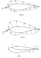
- Figure 1a shows the pressure on a wind turbine blade surface under a low flow velocity and small angle of attack (arrow F1).
- Figure 1b shows the pressure on a wind turbine blade surface under a higher flow velocity and larger angle of attack (arrow F2).
- the wind turbine blade is formed by a first component 11 having a typical aerodynamic profile with a leading edge 5, a trailing edge 7 and suction and pressure sides between the leading edge 5 and the trailing edge 7 and one or several components 13.
- the second components 13 are attached to the trailing edge 7 of the first component 11 and include deflectable flaps 15, 15'.
- the invention also comprises embodiments in which the second components 13 are similarly attached to the leading edge 5 of the first component 11.
- the surface pressure changes illustrated in Figures 1a and 1b are used as a direct or indirect mechanism for actuating said deflectable flaps 15, 15' for reducing the blade loads.
- the duct 19 (it may be for instance a tube or a hose) is able to transfer the specific pressure from the hole 17 in the outer surface of the blade to the scaling device 21 in the inside of the blade to which it is connected. This means that if the pressure changes at the hole 17, where the duct 19 is connected to the surface, the pressure at the entry of the scaling device 21 changes to the same level and it is used to generate a force F or a torque T which changes in parallel to the change in pressure.
- That force F or torque T is used for displacing a deflectable flap 15 upwards or downwards, within the limits set by the flap material and the type of joint between the flap 15 and the first component 11.
- the force F can either be used directly to deflect a flap 15 as schematically shown in Figures 3a and 3b or indirectly to control any suitable actuating device 23 of the flap 15 as schematically shown in Figures 4a and 4b .
- the torque T can be used directly for displacing a deflectable flap 15 upwards or downwards and change the shape of the trailing edge as schematically shown in Figures 5a and 5b .
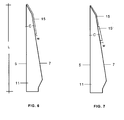
- the blade may include one individual flap 15 as shown in Figure 6 or several flaps 15, 15' as shown in Fig. 7 . In the latter case each flap 15, 15' has its own actuating means.
- the width W of the flap or flaps 15, 15' is comprised between 1-20% of the chord length C in the center of the flap.
- the width W of the flap or flaps 15, 15' may be constant or variable. In the first case the width will be usually smaller close to the tip region and larger towards the root section of the blade. In the latter case, the width W of the flap 15', as shown in Fig. 7 will decrease towards the tip of the blade.
- the flap or flaps 15, 15' are attached to the blade leading edge 5 and/or to the blade trailing edge 7 in a section having a length lesser than 1/3 of the blade length L.
- the flaps 15, 15' are preferably made in one piece of a flexible material such as rubber and it are attached to the first component 11 with means allowing its deflection as explained above. It can also be made as a pultruded profile eg. in glass fiber reinforced composite material.
Landscapes
- Engineering & Computer Science (AREA)
- Physics & Mathematics (AREA)
- Fluid Mechanics (AREA)
- Life Sciences & Earth Sciences (AREA)
- Sustainable Development (AREA)
- Sustainable Energy (AREA)
- Chemical & Material Sciences (AREA)
- Combustion & Propulsion (AREA)
- Mechanical Engineering (AREA)
- General Engineering & Computer Science (AREA)
- Wind Motors (AREA)
Claims (12)
- Un aérogénérateur équipé d'au moins une pale dotée d'un premier élément (11) avec un profil aérodynamique avec un bord d'attaque (5), un bord de fuite (7) et des côtés d'aspiration et de pression entre le bord d'attaque (5) et le bord de fuite (7). Un deuxième élément (13) fixé au bord d'attaque (5) et/ou au bord de fuite (7) du premier élément (11) sur au moins une partie de la pale, dont les caractéristiques sont les suivantes :Le deuxième élément (13) comprend un ou plusieurs volets de déflection vers le haut ou vers le bas (15, 15') permettant de modifier l'écoulement du flux sur la pale ;- la déflection de ces volets (15, 15') se fait au moyen d'une force d'actionnement ou couple fournie par des systèmes de démultiplication (21) connectés à un emplacement prédéterminé (17) sur la surface extérieure de la pale, grâce à un conduit (19), afin que les modifications de la pression du vent au dit emplacement (17) puissent être démultipliées vers ladite force d'actionnement ou couple.
- Un aérogénérateur conforme à la revendication 1, caractérisé par le fait que la fixation de l'un ou de plusieurs volets (15,15') au premier élément (13) et aux appareils démultiplicateurs (21) est configurée de façon à ce que les appareils démultiplicateurs (21) fournissent une force qui est utilisée pour la déflection du ou des volets mentionnés (15, 15').
- Un aérogénérateur conforme à la revendication 2, caractérisé par le fait que ladite force est utilisée directement pour la déflection du ou des volets (15, 15').
- Un aérogénérateur conforme à la revendication 2, caractérisé par le fait que ladite force est utilisée pour contrôler la déflection d'un volet spécifique du ou des volets (15, 15').
- Un aérogénérateur conforme à la revendication 1, caractérisé par le fait que la fixation d'un ou des volets (15) au premier élément et aux appareils démultiplicateurs (21) est configurée de façon à ce que les appareils démultiplicateurs (21) fournissent un couple directement utilisé pour la déflection du ou des volets en question (15, 15').
- Un aérogénérateur conforme à l'une des revendications 1 à 5, caractérisé par le fait que la largeur (l) du ou des volets (15, 15'), représente entre 1 et 20 %de la longueur de corde C de la pale au centre du volet (15, 15').
- Un aérogénérateur conforme à la revendication 6, caractérisé par le fait que la largeur (1) d'au moins un volet (15) est constante le long de la pale.
- Un aérogénérateur conforme à la revendication 6, caractérisé par le fait que la largeur (l) d'au moins un volet (15') est variable le long de la pale.
- Un aérogénérateur conforme à l'une des revendications 1 à 8, caractérisé par le fait que le ou les volets (15, 15') sont fixés au bord d'attaque (5) et/ou au bord de fuite (7) de la pale sur une section d'une longueur inférieure à 1/3 de celle de la pale l.
- Un aérogénérateur conforme à l'une des revendications 1 à 9, caractérisé par le fait que le ou les volets (15, 15') sont constitués d'une pièce unique de matériau souple.
- Un aérogénérateur conforme à la revendication 10, caractérisé par le fait que le ou les volets (15, 15') sont en caoutchouc.
- Un aérogénérateur conforme à la revendication 10, caractérisé par le fait que le ou les volets (15, 15') sont en matériau composite renforcé de fibre de verre pultrudé.
Applications Claiming Priority (1)
| Application Number | Priority Date | Filing Date | Title |
|---|---|---|---|
| ES200702454A ES2326352B1 (es) | 2007-09-14 | 2007-09-14 | Pala de aerogenerador con alerones deflectables controlados por cambios de la presion en la superficie. |
Publications (2)
| Publication Number | Publication Date |
|---|---|
| EP2085609A1 EP2085609A1 (fr) | 2009-08-05 |
| EP2085609B1 true EP2085609B1 (fr) | 2010-11-17 |
Family
ID=40454662
Family Applications (1)
| Application Number | Title | Priority Date | Filing Date |
|---|---|---|---|
| EP08015979A Not-in-force EP2085609B1 (fr) | 2007-09-14 | 2008-09-10 | Pale d'éolienne avec volets de cintrage contrôlés par des changements de pression de surface |
Country Status (6)
| Country | Link |
|---|---|
| US (1) | US8408870B2 (fr) |
| EP (1) | EP2085609B1 (fr) |
| CN (1) | CN101387264B (fr) |
| AT (1) | ATE488694T1 (fr) |
| DE (1) | DE602008003518D1 (fr) |
| ES (1) | ES2326352B1 (fr) |
Families Citing this family (14)
| Publication number | Priority date | Publication date | Assignee | Title |
|---|---|---|---|---|
| EP2350452B2 (fr) † | 2008-10-14 | 2020-08-19 | Vestas Wind Systems A/S | Pale d'éolienne avec dispositif pour modifier la surface ou la forme aérodynamique |
| GB2469854A (en) * | 2009-04-30 | 2010-11-03 | Vestas Wind Sys As | Wind turbine rotor blade |
| WO2011000628A2 (fr) * | 2009-06-30 | 2011-01-06 | Vestas Wind Systems A/S | Contrôle amélioré de pale d'éolienne |
| WO2011026495A2 (fr) * | 2009-09-04 | 2011-03-10 | Vestas Wind Systems A/S | Pale de rotor d'éolienne |
| US20110135485A1 (en) * | 2009-12-30 | 2011-06-09 | Jing Wang | Spar for a wind turbine rotor blade and method for fabricating the same |
| CN102762850B (zh) | 2010-01-14 | 2015-04-08 | 耐普迪考股份有限公司 | 风力涡轮机转子叶片部件及其制造方法 |
| US10137542B2 (en) | 2010-01-14 | 2018-11-27 | Senvion Gmbh | Wind turbine rotor blade components and machine for making same |
| WO2013045601A1 (fr) * | 2011-09-29 | 2013-04-04 | Lm Wind Power A/S | Pale d'éolienne |
| US8506248B2 (en) * | 2011-10-06 | 2013-08-13 | General Electric Company | Wind turbine rotor blade with passively modified trailing edge component |
| US8602732B2 (en) | 2011-10-06 | 2013-12-10 | General Electric Company | Wind turbine rotor blade with passively modified trailing edge component |
| EP2628946B1 (fr) | 2012-02-20 | 2017-09-27 | GE Renewable Technologies | Pale aérodynamique et procédé de contrôle de la portance d'une telle pale |
| US9151270B2 (en) * | 2012-04-03 | 2015-10-06 | Siemens Aktiengesellschaft | Flatback slat for wind turbine |
| CA3016039C (fr) * | 2016-02-29 | 2023-09-26 | Flexsys, Inc. | Agencement de morphage de bord destine a une surface portante |
| EP3919737A1 (fr) * | 2020-06-05 | 2021-12-08 | Siemens Gamesa Renewable Energy A/S | Dispositif et procédé de commande du fonctionnement d'une éolienne pour réduire la charge au désalignement du lacet |
Family Cites Families (14)
| Publication number | Priority date | Publication date | Assignee | Title |
|---|---|---|---|---|
| SE331952B (fr) * | 1967-12-22 | 1971-01-18 | Ingelman Sundberg A | |
| DE2922885A1 (de) * | 1979-06-06 | 1980-12-18 | Wolfgang Rath | Zyklische klappensteuerung fuer windkraftanlagen |
| GR910200234U (en) * | 1990-05-31 | 1992-07-30 | Mihail Valsamidis | Turbine wind machine with a vertical axis |
| US5193978A (en) * | 1991-09-23 | 1993-03-16 | Bill Gutierrez | Articulated blade with automatic pitch and camber control |
| US5375324A (en) * | 1993-07-12 | 1994-12-27 | Flowind Corporation | Vertical axis wind turbine with pultruded blades |
| JP4020783B2 (ja) * | 2000-12-23 | 2007-12-12 | アロイス・ヴォベン | 風力発電のための回転翼 |
| US7059833B2 (en) * | 2001-11-26 | 2006-06-13 | Bonus Energy A/S | Method for improvement of the efficiency of a wind turbine rotor |
| US6769873B2 (en) | 2002-10-08 | 2004-08-03 | The United States Of America As Represented By The Secretary Of The Navy | Dynamically reconfigurable wind turbine blade assembly |
| CN100455793C (zh) | 2003-03-31 | 2009-01-28 | 丹麦技术大学 | 风轮机叶片、风轮机以及控制风轮机工作条件的方法 |
| DK200300670A (da) * | 2003-05-05 | 2004-11-06 | Lm Glasfiber As | Vindmölleving med opdriftsregulerende organer |
| DE10348060B4 (de) * | 2003-10-16 | 2016-10-27 | Windreich GmbH | Rotorblatt eines Rotors einer Windenergieanlage |
| EP1952015B1 (fr) * | 2005-10-17 | 2013-05-15 | Vestas Wind Systems A/S | Pale d aérogénérateur à profil aérodynamique variable |
| BRPI0817359A2 (pt) * | 2007-11-06 | 2016-10-04 | Flexsys Inc | "turbina eólica, arranjo de formação de borda para um aerofólio e arranjo de aerofólio para uma pá de uma turbina eólica" |
| CN101323371B (zh) * | 2008-06-24 | 2010-08-18 | 北京航空航天大学 | 襟翼上具有联合射流结构的增升装置 |
-
2007
- 2007-09-14 ES ES200702454A patent/ES2326352B1/es active Active
-
2008
- 2008-08-29 US US12/200,943 patent/US8408870B2/en not_active Expired - Fee Related
- 2008-09-10 AT AT08015979T patent/ATE488694T1/de not_active IP Right Cessation
- 2008-09-10 DE DE602008003518T patent/DE602008003518D1/de active Active
- 2008-09-10 EP EP08015979A patent/EP2085609B1/fr not_active Not-in-force
- 2008-09-11 CN CN2008102143964A patent/CN101387264B/zh not_active Expired - Fee Related
Also Published As
| Publication number | Publication date |
|---|---|
| ES2326352A1 (es) | 2009-10-07 |
| CN101387264B (zh) | 2012-09-05 |
| ATE488694T1 (de) | 2010-12-15 |
| DE602008003518D1 (de) | 2010-12-30 |
| EP2085609A1 (fr) | 2009-08-05 |
| ES2326352B1 (es) | 2010-07-15 |
| US20090074573A1 (en) | 2009-03-19 |
| US8408870B2 (en) | 2013-04-02 |
| CN101387264A (zh) | 2009-03-18 |
Similar Documents
| Publication | Publication Date | Title |
|---|---|---|
| EP2085609B1 (fr) | Pale d'éolienne avec volets de cintrage contrôlés par des changements de pression de surface | |
| EP2034178B1 (fr) | Pale d'éolienne équipée de volets orientables | |
| US8087888B2 (en) | Wind turbine blade with cambering flaps | |
| US8827644B2 (en) | Wind turbine rotor blade | |
| EP2267298A2 (fr) | Pale d'éolienne à ailettes rotatives à son extrémité | |
| CN105980701B (zh) | 用于减轻风力涡轮机的转子叶片上的应变的装置 | |
| EP2389510B1 (fr) | Commande d'un rotor d'eolienne au cours d'un processus d'arret par tangage et dispositif de modification de surface | |
| CN101922407B (zh) | 能够以扭转的方式加载的风力涡轮叶片 | |
| CN103032261A (zh) | 具有被动修改的后缘部件的风力涡轮机转子叶片 | |
| US20070231151A1 (en) | Active flow control for wind turbine blades | |
| EP2840256B1 (fr) | Pale de turbine éolienne | |
| EP2998571B1 (fr) | Dispositif influençant le levage d'une pale de rotor d'une éolienne | |
| GB2486876A (en) | Wind turbine blade flap | |
| Hulskamp et al. | Implementation of the ‘smart’rotor concept |
Legal Events
| Date | Code | Title | Description |
|---|---|---|---|
| PUAI | Public reference made under article 153(3) epc to a published international application that has entered the european phase |
Free format text: ORIGINAL CODE: 0009012 |
|
| AK | Designated contracting states |
Kind code of ref document: A1 Designated state(s): AT BE BG CH CY CZ DE DK EE ES FI FR GB GR HR HU IE IS IT LI LT LU LV MC MT NL NO PL PT RO SE SI SK TR |
|
| AX | Request for extension of the european patent |
Extension state: AL BA MK RS |
|
| 17P | Request for examination filed |
Effective date: 20100201 |
|
| AKX | Designation fees paid |
Designated state(s): AT BE BG CH CY CZ DE DK EE ES FI FR GB GR HR HU IE IS IT LI LT LU LV MC MT NL NO PL PT RO SE SI SK TR |
|
| GRAP | Despatch of communication of intention to grant a patent |
Free format text: ORIGINAL CODE: EPIDOSNIGR1 |
|
| GRAS | Grant fee paid |
Free format text: ORIGINAL CODE: EPIDOSNIGR3 |
|
| GRAA | (expected) grant |
Free format text: ORIGINAL CODE: 0009210 |
|
| AK | Designated contracting states |
Kind code of ref document: B1 Designated state(s): AT BE BG CH CY CZ DE DK EE ES FI FR GB GR HR HU IE IS IT LI LT LU LV MC MT NL NO PL PT RO SE SI SK TR |
|
| REG | Reference to a national code |
Ref country code: GB Ref legal event code: FG4D |
|
| REG | Reference to a national code |
Ref country code: CH Ref legal event code: EP |
|
| REG | Reference to a national code |
Ref country code: IE Ref legal event code: FG4D |
|
| REF | Corresponds to: |
Ref document number: 602008003518 Country of ref document: DE Date of ref document: 20101230 Kind code of ref document: P |
|
| REG | Reference to a national code |
Ref country code: NL Ref legal event code: VDEP Effective date: 20101117 |
|
| LTIE | Lt: invalidation of european patent or patent extension |
Effective date: 20101117 |
|
| PG25 | Lapsed in a contracting state [announced via postgrant information from national office to epo] |
Ref country code: LT Free format text: LAPSE BECAUSE OF FAILURE TO SUBMIT A TRANSLATION OF THE DESCRIPTION OR TO PAY THE FEE WITHIN THE PRESCRIBED TIME-LIMIT Effective date: 20101117 Ref country code: NO Free format text: LAPSE BECAUSE OF FAILURE TO SUBMIT A TRANSLATION OF THE DESCRIPTION OR TO PAY THE FEE WITHIN THE PRESCRIBED TIME-LIMIT Effective date: 20110217 |
|
| PG25 | Lapsed in a contracting state [announced via postgrant information from national office to epo] |
Ref country code: CY Free format text: LAPSE BECAUSE OF FAILURE TO SUBMIT A TRANSLATION OF THE DESCRIPTION OR TO PAY THE FEE WITHIN THE PRESCRIBED TIME-LIMIT Effective date: 20101117 Ref country code: SE Free format text: LAPSE BECAUSE OF FAILURE TO SUBMIT A TRANSLATION OF THE DESCRIPTION OR TO PAY THE FEE WITHIN THE PRESCRIBED TIME-LIMIT Effective date: 20101117 Ref country code: LV Free format text: LAPSE BECAUSE OF FAILURE TO SUBMIT A TRANSLATION OF THE DESCRIPTION OR TO PAY THE FEE WITHIN THE PRESCRIBED TIME-LIMIT Effective date: 20101117 Ref country code: IS Free format text: LAPSE BECAUSE OF FAILURE TO SUBMIT A TRANSLATION OF THE DESCRIPTION OR TO PAY THE FEE WITHIN THE PRESCRIBED TIME-LIMIT Effective date: 20110317 Ref country code: NL Free format text: LAPSE BECAUSE OF FAILURE TO SUBMIT A TRANSLATION OF THE DESCRIPTION OR TO PAY THE FEE WITHIN THE PRESCRIBED TIME-LIMIT Effective date: 20101117 Ref country code: AT Free format text: LAPSE BECAUSE OF FAILURE TO SUBMIT A TRANSLATION OF THE DESCRIPTION OR TO PAY THE FEE WITHIN THE PRESCRIBED TIME-LIMIT Effective date: 20101117 Ref country code: PT Free format text: LAPSE BECAUSE OF FAILURE TO SUBMIT A TRANSLATION OF THE DESCRIPTION OR TO PAY THE FEE WITHIN THE PRESCRIBED TIME-LIMIT Effective date: 20110317 Ref country code: BG Free format text: LAPSE BECAUSE OF FAILURE TO SUBMIT A TRANSLATION OF THE DESCRIPTION OR TO PAY THE FEE WITHIN THE PRESCRIBED TIME-LIMIT Effective date: 20110217 Ref country code: SI Free format text: LAPSE BECAUSE OF FAILURE TO SUBMIT A TRANSLATION OF THE DESCRIPTION OR TO PAY THE FEE WITHIN THE PRESCRIBED TIME-LIMIT Effective date: 20101117 Ref country code: HR Free format text: LAPSE BECAUSE OF FAILURE TO SUBMIT A TRANSLATION OF THE DESCRIPTION OR TO PAY THE FEE WITHIN THE PRESCRIBED TIME-LIMIT Effective date: 20101117 Ref country code: FI Free format text: LAPSE BECAUSE OF FAILURE TO SUBMIT A TRANSLATION OF THE DESCRIPTION OR TO PAY THE FEE WITHIN THE PRESCRIBED TIME-LIMIT Effective date: 20101117 |
|
| PG25 | Lapsed in a contracting state [announced via postgrant information from national office to epo] |
Ref country code: GR Free format text: LAPSE BECAUSE OF FAILURE TO SUBMIT A TRANSLATION OF THE DESCRIPTION OR TO PAY THE FEE WITHIN THE PRESCRIBED TIME-LIMIT Effective date: 20110218 |
|
| PG25 | Lapsed in a contracting state [announced via postgrant information from national office to epo] |
Ref country code: EE Free format text: LAPSE BECAUSE OF FAILURE TO SUBMIT A TRANSLATION OF THE DESCRIPTION OR TO PAY THE FEE WITHIN THE PRESCRIBED TIME-LIMIT Effective date: 20101117 Ref country code: CZ Free format text: LAPSE BECAUSE OF FAILURE TO SUBMIT A TRANSLATION OF THE DESCRIPTION OR TO PAY THE FEE WITHIN THE PRESCRIBED TIME-LIMIT Effective date: 20101117 Ref country code: ES Free format text: LAPSE BECAUSE OF FAILURE TO SUBMIT A TRANSLATION OF THE DESCRIPTION OR TO PAY THE FEE WITHIN THE PRESCRIBED TIME-LIMIT Effective date: 20110228 Ref country code: BE Free format text: LAPSE BECAUSE OF FAILURE TO SUBMIT A TRANSLATION OF THE DESCRIPTION OR TO PAY THE FEE WITHIN THE PRESCRIBED TIME-LIMIT Effective date: 20101117 |
|
| PG25 | Lapsed in a contracting state [announced via postgrant information from national office to epo] |
Ref country code: PL Free format text: LAPSE BECAUSE OF FAILURE TO SUBMIT A TRANSLATION OF THE DESCRIPTION OR TO PAY THE FEE WITHIN THE PRESCRIBED TIME-LIMIT Effective date: 20101117 Ref country code: RO Free format text: LAPSE BECAUSE OF FAILURE TO SUBMIT A TRANSLATION OF THE DESCRIPTION OR TO PAY THE FEE WITHIN THE PRESCRIBED TIME-LIMIT Effective date: 20101117 Ref country code: SK Free format text: LAPSE BECAUSE OF FAILURE TO SUBMIT A TRANSLATION OF THE DESCRIPTION OR TO PAY THE FEE WITHIN THE PRESCRIBED TIME-LIMIT Effective date: 20101117 Ref country code: DK Free format text: LAPSE BECAUSE OF FAILURE TO SUBMIT A TRANSLATION OF THE DESCRIPTION OR TO PAY THE FEE WITHIN THE PRESCRIBED TIME-LIMIT Effective date: 20101117 |
|
| PLBE | No opposition filed within time limit |
Free format text: ORIGINAL CODE: 0009261 |
|
| STAA | Information on the status of an ep patent application or granted ep patent |
Free format text: STATUS: NO OPPOSITION FILED WITHIN TIME LIMIT |
|
| 26N | No opposition filed |
Effective date: 20110818 |
|
| REG | Reference to a national code |
Ref country code: DE Ref legal event code: R097 Ref document number: 602008003518 Country of ref document: DE Effective date: 20110818 |
|
| PG25 | Lapsed in a contracting state [announced via postgrant information from national office to epo] |
Ref country code: IT Free format text: LAPSE BECAUSE OF FAILURE TO SUBMIT A TRANSLATION OF THE DESCRIPTION OR TO PAY THE FEE WITHIN THE PRESCRIBED TIME-LIMIT Effective date: 20101117 |
|
| PG25 | Lapsed in a contracting state [announced via postgrant information from national office to epo] |
Ref country code: MC Free format text: LAPSE BECAUSE OF NON-PAYMENT OF DUE FEES Effective date: 20110930 |
|
| REG | Reference to a national code |
Ref country code: IE Ref legal event code: MM4A |
|
| REG | Reference to a national code |
Ref country code: FR Ref legal event code: ST Effective date: 20120531 |
|
| REG | Reference to a national code |
Ref country code: DE Ref legal event code: R119 Ref document number: 602008003518 Country of ref document: DE Effective date: 20120403 |
|
| PG25 | Lapsed in a contracting state [announced via postgrant information from national office to epo] |
Ref country code: DE Free format text: LAPSE BECAUSE OF NON-PAYMENT OF DUE FEES Effective date: 20120403 Ref country code: IE Free format text: LAPSE BECAUSE OF NON-PAYMENT OF DUE FEES Effective date: 20110910 |
|
| PG25 | Lapsed in a contracting state [announced via postgrant information from national office to epo] |
Ref country code: FR Free format text: LAPSE BECAUSE OF NON-PAYMENT OF DUE FEES Effective date: 20110930 |
|
| PG25 | Lapsed in a contracting state [announced via postgrant information from national office to epo] |
Ref country code: MT Free format text: LAPSE BECAUSE OF FAILURE TO SUBMIT A TRANSLATION OF THE DESCRIPTION OR TO PAY THE FEE WITHIN THE PRESCRIBED TIME-LIMIT Effective date: 20101117 |
|
| REG | Reference to a national code |
Ref country code: CH Ref legal event code: PL |
|
| GBPC | Gb: european patent ceased through non-payment of renewal fee |
Effective date: 20120910 |
|
| PG25 | Lapsed in a contracting state [announced via postgrant information from national office to epo] |
Ref country code: LU Free format text: LAPSE BECAUSE OF NON-PAYMENT OF DUE FEES Effective date: 20110910 |
|
| PG25 | Lapsed in a contracting state [announced via postgrant information from national office to epo] |
Ref country code: LI Free format text: LAPSE BECAUSE OF NON-PAYMENT OF DUE FEES Effective date: 20120930 Ref country code: GB Free format text: LAPSE BECAUSE OF NON-PAYMENT OF DUE FEES Effective date: 20120910 Ref country code: CH Free format text: LAPSE BECAUSE OF NON-PAYMENT OF DUE FEES Effective date: 20120930 |
|
| PG25 | Lapsed in a contracting state [announced via postgrant information from national office to epo] |
Ref country code: TR Free format text: LAPSE BECAUSE OF FAILURE TO SUBMIT A TRANSLATION OF THE DESCRIPTION OR TO PAY THE FEE WITHIN THE PRESCRIBED TIME-LIMIT Effective date: 20101117 |
|
| PG25 | Lapsed in a contracting state [announced via postgrant information from national office to epo] |
Ref country code: HU Free format text: LAPSE BECAUSE OF FAILURE TO SUBMIT A TRANSLATION OF THE DESCRIPTION OR TO PAY THE FEE WITHIN THE PRESCRIBED TIME-LIMIT Effective date: 20101117 |