EP2085697A2 - Verbrennungsvorrichtung - Google Patents
Verbrennungsvorrichtung Download PDFInfo
- Publication number
- EP2085697A2 EP2085697A2 EP09250059A EP09250059A EP2085697A2 EP 2085697 A2 EP2085697 A2 EP 2085697A2 EP 09250059 A EP09250059 A EP 09250059A EP 09250059 A EP09250059 A EP 09250059A EP 2085697 A2 EP2085697 A2 EP 2085697A2
- Authority
- EP
- European Patent Office
- Prior art keywords
- wall
- wall element
- combustor
- gas turbine
- element according
- Prior art date
- Legal status (The legal status is an assumption and is not a legal conclusion. Google has not performed a legal analysis and makes no representation as to the accuracy of the status listed.)
- Withdrawn
Links
- 238000002485 combustion reaction Methods 0.000 title claims abstract description 15
- 239000000919 ceramic Substances 0.000 claims abstract description 30
- PNEYBMLMFCGWSK-UHFFFAOYSA-N aluminium oxide Inorganic materials [O-2].[O-2].[O-2].[Al+3].[Al+3] PNEYBMLMFCGWSK-UHFFFAOYSA-N 0.000 claims description 11
- 210000003041 ligament Anatomy 0.000 claims description 9
- PXHVJJICTQNCMI-UHFFFAOYSA-N Nickel Chemical group [Ni] PXHVJJICTQNCMI-UHFFFAOYSA-N 0.000 claims description 8
- 229910045601 alloy Inorganic materials 0.000 claims description 6
- 239000000956 alloy Substances 0.000 claims description 6
- 229910052759 nickel Inorganic materials 0.000 claims description 4
- 239000002002 slurry Substances 0.000 claims description 4
- 238000010304 firing Methods 0.000 claims description 2
- 239000000446 fuel Substances 0.000 description 6
- 239000000203 mixture Substances 0.000 description 5
- 229910000990 Ni alloy Inorganic materials 0.000 description 3
- 229910010293 ceramic material Inorganic materials 0.000 description 3
- 238000001816 cooling Methods 0.000 description 3
- 239000002184 metal Substances 0.000 description 3
- 229910052751 metal Inorganic materials 0.000 description 3
- 230000001141 propulsive effect Effects 0.000 description 3
- 230000000694 effects Effects 0.000 description 2
- 238000004519 manufacturing process Methods 0.000 description 2
- WYTGDNHDOZPMIW-RCBQFDQVSA-N alstonine Natural products C1=CC2=C3C=CC=CC3=NC2=C2N1C[C@H]1[C@H](C)OC=C(C(=O)OC)[C@H]1C2 WYTGDNHDOZPMIW-RCBQFDQVSA-N 0.000 description 1
- 239000002131 composite material Substances 0.000 description 1
- 230000006835 compression Effects 0.000 description 1
- 238000007906 compression Methods 0.000 description 1
- 239000002826 coolant Substances 0.000 description 1
- 239000012809 cooling fluid Substances 0.000 description 1
- 238000005336 cracking Methods 0.000 description 1
- 238000005520 cutting process Methods 0.000 description 1
- 238000013016 damping Methods 0.000 description 1
- 238000005516 engineering process Methods 0.000 description 1
- 239000002241 glass-ceramic Substances 0.000 description 1
- 229910000856 hastalloy Inorganic materials 0.000 description 1
- 239000000463 material Substances 0.000 description 1
- 229910001092 metal group alloy Inorganic materials 0.000 description 1
- 229910001235 nimonic Inorganic materials 0.000 description 1
- 239000007921 spray Substances 0.000 description 1
- 238000011144 upstream manufacturing Methods 0.000 description 1
Images


Classifications
-
- F—MECHANICAL ENGINEERING; LIGHTING; HEATING; WEAPONS; BLASTING
- F23—COMBUSTION APPARATUS; COMBUSTION PROCESSES
- F23R—GENERATING COMBUSTION PRODUCTS OF HIGH PRESSURE OR HIGH VELOCITY, e.g. GAS-TURBINE COMBUSTION CHAMBERS
- F23R3/00—Continuous combustion chambers using liquid or gaseous fuel
- F23R3/007—Continuous combustion chambers using liquid or gaseous fuel constructed mainly of ceramic components
-
- F—MECHANICAL ENGINEERING; LIGHTING; HEATING; WEAPONS; BLASTING
- F23—COMBUSTION APPARATUS; COMBUSTION PROCESSES
- F23M—CASINGS, LININGS, WALLS OR DOORS SPECIALLY ADAPTED FOR COMBUSTION CHAMBERS, e.g. FIREBRIDGES; DEVICES FOR DEFLECTING AIR, FLAMES OR COMBUSTION PRODUCTS IN COMBUSTION CHAMBERS; SAFETY ARRANGEMENTS SPECIALLY ADAPTED FOR COMBUSTION APPARATUS; DETAILS OF COMBUSTION CHAMBERS, NOT OTHERWISE PROVIDED FOR
- F23M5/00—Casings; Linings; Walls
- F23M5/04—Supports for linings
-
- F—MECHANICAL ENGINEERING; LIGHTING; HEATING; WEAPONS; BLASTING
- F23—COMBUSTION APPARATUS; COMBUSTION PROCESSES
- F23R—GENERATING COMBUSTION PRODUCTS OF HIGH PRESSURE OR HIGH VELOCITY, e.g. GAS-TURBINE COMBUSTION CHAMBERS
- F23R3/00—Continuous combustion chambers using liquid or gaseous fuel
- F23R3/42—Continuous combustion chambers using liquid or gaseous fuel characterised by the arrangement or form of the flame tubes or combustion chambers
- F23R3/60—Support structures; Attaching or mounting means
-
- F—MECHANICAL ENGINEERING; LIGHTING; HEATING; WEAPONS; BLASTING
- F23—COMBUSTION APPARATUS; COMBUSTION PROCESSES
- F23M—CASINGS, LININGS, WALLS OR DOORS SPECIALLY ADAPTED FOR COMBUSTION CHAMBERS, e.g. FIREBRIDGES; DEVICES FOR DEFLECTING AIR, FLAMES OR COMBUSTION PRODUCTS IN COMBUSTION CHAMBERS; SAFETY ARRANGEMENTS SPECIALLY ADAPTED FOR COMBUSTION APPARATUS; DETAILS OF COMBUSTION CHAMBERS, NOT OTHERWISE PROVIDED FOR
- F23M2900/00—Special features of, or arrangements for combustion chambers
- F23M2900/05002—Means for accommodate thermal expansion of the wall liner
-
- F—MECHANICAL ENGINEERING; LIGHTING; HEATING; WEAPONS; BLASTING
- F23—COMBUSTION APPARATUS; COMBUSTION PROCESSES
- F23M—CASINGS, LININGS, WALLS OR DOORS SPECIALLY ADAPTED FOR COMBUSTION CHAMBERS, e.g. FIREBRIDGES; DEVICES FOR DEFLECTING AIR, FLAMES OR COMBUSTION PRODUCTS IN COMBUSTION CHAMBERS; SAFETY ARRANGEMENTS SPECIALLY ADAPTED FOR COMBUSTION APPARATUS; DETAILS OF COMBUSTION CHAMBERS, NOT OTHERWISE PROVIDED FOR
- F23M2900/00—Special features of, or arrangements for combustion chambers
- F23M2900/05004—Special materials for walls or lining
-
- F—MECHANICAL ENGINEERING; LIGHTING; HEATING; WEAPONS; BLASTING
- F23—COMBUSTION APPARATUS; COMBUSTION PROCESSES
- F23R—GENERATING COMBUSTION PRODUCTS OF HIGH PRESSURE OR HIGH VELOCITY, e.g. GAS-TURBINE COMBUSTION CHAMBERS
- F23R2900/00—Special features of, or arrangements for continuous combustion chambers; Combustion processes therefor
- F23R2900/00017—Assembling combustion chamber liners or subparts
Definitions
- This invention relates to improvements to a combustor of a gas turbine engine and in particular to an arrangement of heat resistant tiles of a double wall of a combustor.
- Tiles are typically formed from high temperature resistant nickel alloys which are secured to the outer wall by studs integral to the tile, washers and nuts.
- Combustors are required to operate at ever higher temperatures to increase efficiency of the engine. However, in order to reduce emissions from the engine, more and more of the air flow through the engine is required to be used in the combustion process leaving less air available for use as a coolant of the combustor walls.
- a ceramic pin extends through an aperture in the ceramic tile and through a corresponding aperture in the metallic combustor wall and is secured by an expansion resistant fastening.
- a ceramic tile is provided with a centrally arranged integral ceramic projection that is inserted through and secured by an aperture in a glass ceramic composite support plate.
- a gas turbine combustor wall element for attaching to an outer wall of a gas turbine combustor, the wall element comprising:
- the ligaments follow a serpentine path which mitigates stresses caused by the difference in the thermal expansion coefficient of the support and ceramic body when the wall element is heated in use.
- attachment means protruding from the body.
- the attachment means are joined to a common support at respective join locations.
- the respective join locations are connected by a ligament. Possibly a plurality of ligaments radiate from the join location.
- the support and attachment means may be joined by a weld.
- the support is preferably metallic and possibly a nickel based alloy.
- the ceramic body comprises alumina which is possibly formed by firing alumina fibres in an alumina slurry.
- the attachment means may comprise a threaded fastener and possibly the threaded fastener is a threaded shank.
- the wall element may be incorporated into a combustor which may be used in a gas turbine engine. There may be an air gap between the ceramic body and the combustion space wall and the wall element may be secured to a combustor outer wall by a fastener.
- a ducted fan gas turbine engine generally indicated at 10 has a principal axis X-X.
- the engine 10 comprises, in axial flow series, an air intake 11, a propulsive fan 12, an intermediate pressure compressor 13, a high-pressure compressor 14, combustion equipment 15, a high-pressure turbine 16, an intermediate pressure turbine 17, a low-pressure turbine 18 and an exhaust nozzle 19.
- the gas turbine engine 10 works in the conventional manner so that air entering the intake 11 is accelerated by the fan 12 to produce two air flows, a first air flow into the intermediate pressure compressor 13 and a second air flow which provides propulsive thrust.
- the intermediate pressure compressor 13 compresses the airflow directed into it before delivering that air to the high-pressure compressor 14 where further compression takes place.
- the compressed air exhausted from the high-pressure compressor 14 is directed into the combustion equipment 15 where it is mixed with fuel and the mixture combusted.
- the resultant hot combustion products then expand through, and thereby drive, the high, intermediate and low-pressure turbine 16, 17 and 18 before being exhausted through the nozzle 19 to provide additional propulsive thrust.
- the high, intermediate and low-pressure turbines 16, 17 and 18 respectively drive the high and intermediate pressure compressors 14 and 13 and the fan 12 by suitable interconnecting shafts (not referenced).
- the combustor 15 is constituted by an annular combustion chamber 20 having radially inner and outer wall structures 21 and 22 respectively.
- the combustor 15 is secured to a wall 23 by a plurality of pins 24 (only one of which is shown).
- Fuel is directed into the chamber 20 through a number of fuel nozzles 25 located at an upstream end 26 of the chamber 20.
- the fuel nozzles 25 are circumferentially spaced around the engine 10 and serve to spray fuel into air derived from the high-pressure compressor 14. The resultant fuel/air mixture is then combusted within the chamber 20.
- the combustion process takes place within the chamber 20 and naturally generates a large amount of heat. It is necessary therefore, to arrange that the inner and outer wall structures 21 and 22 are capable of withstanding the heat.
- the radially inner and outer wall structures 21 and 22 each comprise an outer wall 27 and an inner wall 28.
- the inner wall 28 is made up of a plurality of discrete wall elements in the form of tiles 29A and 29B.
- Each of the tiles 29A, 29B has circumferentially extending edges 30 and 31, and the tiles are positioned adjacent each other, such that the edges 30 and 31 of adjacent tiles 29A, 29B overlap each other. Alternatively, the edges 30, 31 of adjacent tiles can abut each other.
- Each tile 29A, 29B comprises a base portion 32 which is spaced from the outer wall 27 to define therebetween a space for the flow of cooling fluid in the form of cooling air as will be explained below. Heat removal features in the form of pedestals can be provided on the base portion 32 and extend into the space 44 towards the outer wall 27.
- the combustor 20 is subject to varying amounts of combustion heat. This causes the tiles 29A and 29B to thermally expand relative to the outer walls 27. Where the tile is of a ceramic material it is not possible to use the ceramic material to directly fix the tile to the outer wall as the ceramic is too brittle.
- an internal structure is used to both re-enforce the tile and to provide mechanical fixing attachments.
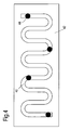
- the internal structure is in the form of a sheet metal cut profile 40 having a serpentine form that limits the effect of differential thermal expansion rates between the ceramic of the tile and the internal structure.
- the tile is formed of Alumina with an internal support of a high temperature nickel based alloy such as C263.
- This alloy is commercially available under the tradenames Nicrofer 5120, Hastelloy C263 and Nimonic 263.
- a C263 alloy has a typical composition of (by wt%): Cr 19.0 - 21.0, Mn up to 0.6, Si up to 0.4; C 0.04 - 0.08, Al 0.3 - 0.6, Ag up to 0.0005, Cu up to 0.2, Mo 5.6 - 6.1, Co 19.0 - 21.0, Ti 1.9 - 2.4, Pb up to 0.002, Zr up to 0.02, P up to 0.015, Fe up to 0.7, S up to 0.007, B up to 0.005.
- the balance is nickel and the total amount of Al plus Ti in the composition should be 2.4 - 2.8. It will be appreciated that other alloys will be suitable.
- C263 has a thermal coefficient of expansion is 13.4 x 10 -6 m/m.K
- the tile is around 100mm by 80 mm in plan and has a curvature to fit a combustor wall of approximately 450mm diameter.
- the tile has a thickness of around 5mm. It will be appreciated that these figures are exemplary and another other size of tile may be used.
- a sheet of C263 with a thickness of around 1mm is cut or stamped to the desired form and a number of attachment features welded thereon.
- the attachment features have a screw thread and are arranged to pass through apertures in the outer wall 46 of the combustor.
- a nut 48 and washer 50 are screwed onto the attachment features to secure the tile to the combustor wall.
- the combustor wall is formed of a nickel alloy of the same composition as that of the tile internal support.
- a series of layers formed of alumina fibres are applied around the support structure and alumina slurry used to bind the layers to the support.
- the alumina fibres and slurry are then fired in a furnace before being machined to improve the surface finish or to form cooling apertures to allow the passage of air from a plenum into the combustion chamber.
- the tile is installed within the combustor by inserting attachment features through the outer combustor wall and applying a nut onto the threaded end.
- a resilient washer or spring element may be provided to provide a damping effect and to aid spacing alignment between the tile and the outer wall.
- the internal support is provided with relieving features which, in this embodiment, are provided by the serpentine ligaments between the joins where the attachment features are secured to the support.
- each tile is bowed such that when multiple tiles are secured to the outer wall of the combustor the tiles uniformly curve around the wall.
- the tiles tend to try and straighten to cause potential rotation in the direction of arrows 60.
- Towards the edges of the tile the forces generated by such movements can create cracking in the ceramic material 42 which can be exacerbated by the use of dissimilar materials such as metal alloys in the tiles.
- the relieving features in the tile internal support structure reduces the stress build up by allowing the metal support to flex.
- the above embodiment enables the manufacture ceramic tiles that locate to a combustor at more than one attachment point.
- the internal support also allows of larger ceramic tiles connecting to a combustor through a single attachment point.
- Alternative embodiments are exemplified in Figure 5 and 6 .
- shaped tiles are provided with a single attachment point. From the attachment points a series of internal structures radiate outwards towards the edge of the tiles. As in the embodiment described with reference to Figures 3 and 4 the structures are formed by cutting or stamping an appropriate metal around which the ceramic is formed.
- the shape of the support permits flexure in union with any tile growth or movement.
Landscapes
- Engineering & Computer Science (AREA)
- Chemical & Material Sciences (AREA)
- Combustion & Propulsion (AREA)
- Mechanical Engineering (AREA)
- General Engineering & Computer Science (AREA)
- Ceramic Engineering (AREA)
- Ceramic Products (AREA)
- Turbine Rotor Nozzle Sealing (AREA)
- Structures Of Non-Positive Displacement Pumps (AREA)
- Gas Burners (AREA)
Applications Claiming Priority (1)
| Application Number | Priority Date | Filing Date | Title |
|---|---|---|---|
| GBGB0801839.2A GB0801839D0 (en) | 2008-02-01 | 2008-02-01 | combustion apparatus |
Publications (2)
| Publication Number | Publication Date |
|---|---|
| EP2085697A2 true EP2085697A2 (de) | 2009-08-05 |
| EP2085697A3 EP2085697A3 (de) | 2014-09-03 |
Family
ID=39186699
Family Applications (1)
| Application Number | Title | Priority Date | Filing Date |
|---|---|---|---|
| EP09250059.4A Withdrawn EP2085697A3 (de) | 2008-02-01 | 2009-01-09 | Verbrennungsvorrichtung |
Country Status (3)
| Country | Link |
|---|---|
| US (1) | US8256224B2 (de) |
| EP (1) | EP2085697A3 (de) |
| GB (1) | GB0801839D0 (de) |
Cited By (2)
| Publication number | Priority date | Publication date | Assignee | Title |
|---|---|---|---|---|
| WO2014158252A1 (en) * | 2013-03-14 | 2014-10-02 | Rolls-Royce Corporation | Bi-metal fastener for thermal growth compensation |
| EP2952813A1 (de) * | 2014-06-05 | 2015-12-09 | Rolls-Royce North American Technologies, Inc. | Brennkammer mit gefliester auskleidung |
Families Citing this family (25)
| Publication number | Priority date | Publication date | Assignee | Title |
|---|---|---|---|---|
| US20110185739A1 (en) * | 2010-01-29 | 2011-08-04 | Honeywell International Inc. | Gas turbine combustors with dual walled liners |
| US10605200B2 (en) * | 2013-01-11 | 2020-03-31 | United Technologies Corporation | Serpentine baffle for a gas turbine engine exhaust duct |
| US20140223919A1 (en) * | 2013-02-14 | 2014-08-14 | United Technologies Corporation | Flexible liner hanger |
| US9709274B2 (en) * | 2013-03-15 | 2017-07-18 | Rolls-Royce Plc | Auxetic structure with stress-relief features |
| WO2014149108A1 (en) | 2013-03-15 | 2014-09-25 | Graves Charles B | Shell and tiled liner arrangement for a combustor |
| US10634351B2 (en) | 2013-04-12 | 2020-04-28 | United Technologies Corporation | Combustor panel T-junction cooling |
| WO2015009384A1 (en) * | 2013-07-16 | 2015-01-22 | United Technologies Corporation | Gas turbine engine with ceramic panel |
| CN105518389B (zh) | 2013-09-11 | 2017-10-24 | 通用电气公司 | 弹簧加载且密封的陶瓷基质复合物燃烧器衬套 |
| WO2015039074A1 (en) | 2013-09-16 | 2015-03-19 | United Technologies Corporation | Controlled variation of pressure drop through effusion cooling in a double walled combustor of a gas turbine engine |
| WO2015039075A1 (en) | 2013-09-16 | 2015-03-19 | United Technologies Corporation | Angled combustor liner cooling holes through transverse structure within a gas turbine engine combustor |
| EP3060847B1 (de) | 2013-10-24 | 2019-09-18 | United Technologies Corporation | Durchgangsgeometrie für eine gasturbinenbrennkammer |
| US10240790B2 (en) | 2013-11-04 | 2019-03-26 | United Technologies Corporation | Turbine engine combustor heat shield with multi-height rails |
| EP3066390B1 (de) | 2013-11-04 | 2020-10-21 | United Technologies Corporation | Wandanordnung eines gasturbinenmotors mit versetzter schiene |
| EP3084310A4 (de) | 2013-12-19 | 2017-01-04 | United Technologies Corporation | Gasturbinenmotorwandanordnung mit umlaufender schienenbolzenarchitektur |
| US10234140B2 (en) | 2013-12-31 | 2019-03-19 | United Technologies Corporation | Gas turbine engine wall assembly with enhanced flow architecture |
| US10648669B2 (en) * | 2015-08-21 | 2020-05-12 | Rolls-Royce Corporation | Case and liner arrangement for a combustor |
| US10669939B2 (en) | 2016-10-26 | 2020-06-02 | Raytheon Technologies Corporation | Combustor seal for a gas turbine engine combustor |
| US10823410B2 (en) | 2016-10-26 | 2020-11-03 | Raytheon Technologies Corporation | Cast combustor liner panel radius for gas turbine engine combustor |
| US10670269B2 (en) | 2016-10-26 | 2020-06-02 | Raytheon Technologies Corporation | Cast combustor liner panel gating feature for a gas turbine engine combustor |
| US10830448B2 (en) | 2016-10-26 | 2020-11-10 | Raytheon Technologies Corporation | Combustor liner panel with a multiple of heat transfer augmentors for a gas turbine engine combustor |
| US10935235B2 (en) | 2016-11-10 | 2021-03-02 | Raytheon Technologies Corporation | Non-planar combustor liner panel for a gas turbine engine combustor |
| US10830433B2 (en) | 2016-11-10 | 2020-11-10 | Raytheon Technologies Corporation | Axial non-linear interface for combustor liner panels in a gas turbine combustor |
| US10935236B2 (en) | 2016-11-10 | 2021-03-02 | Raytheon Technologies Corporation | Non-planar combustor liner panel for a gas turbine engine combustor |
| US10655853B2 (en) | 2016-11-10 | 2020-05-19 | United Technologies Corporation | Combustor liner panel with non-linear circumferential edge for a gas turbine engine combustor |
| US10935243B2 (en) | 2016-11-30 | 2021-03-02 | Raytheon Technologies Corporation | Regulated combustor liner panel for a gas turbine engine combustor |
Citations (3)
| Publication number | Priority date | Publication date | Assignee | Title |
|---|---|---|---|---|
| US5553455A (en) | 1987-12-21 | 1996-09-10 | United Technologies Corporation | Hybrid ceramic article |
| US5957087A (en) | 1998-06-08 | 1999-09-28 | Bonder; Carol P. | Bird feeder with a removable feed drawer |
| US5957067A (en) | 1997-07-28 | 1999-09-28 | Abb Research Ltd. | Ceramic liner |
Family Cites Families (55)
| Publication number | Priority date | Publication date | Assignee | Title |
|---|---|---|---|---|
| US1451887A (en) * | 1920-08-10 | 1923-04-17 | Henry Furnace And Foundry Comp | Hot-air conduit |
| CH255541A (de) * | 1947-05-12 | 1948-06-30 | Bbc Brown Boveri & Cie | Gekühlte metallische Brennkammer zur Erzeugung von Heiz- und Treibgasen. |
| US2933895A (en) * | 1957-12-31 | 1960-04-26 | Gen Electric | Combustion chamber |
| US2916878A (en) * | 1958-04-03 | 1959-12-15 | Gen Electric | Air-directing vane structure for fluid fuel combustor |
| US3295280A (en) * | 1964-04-09 | 1967-01-03 | S Obermayer Co | Furnace wall anchoring structures |
| GB1503921A (en) | 1975-12-19 | 1978-03-15 | Rolls Royce | Method of manufacturing combustion chambers for gas turbine engines |
| US4030875A (en) * | 1975-12-22 | 1977-06-21 | General Electric Company | Integrated ceramic-metal combustor |
| US4315405A (en) * | 1978-12-09 | 1982-02-16 | Rolls-Royce Limited | Combustion apparatus |
| JPS5966619A (ja) * | 1982-10-06 | 1984-04-16 | Hitachi Ltd | ガスタ−ビン燃焼器 |
| CH657151A5 (de) | 1983-10-26 | 1986-08-15 | Bbc Brown Boveri & Cie | Vorrichtung zum zonengluehen eines aus einem hochtemperatur-werkstoff bestehenden werkstuecks und verfahren zum zonengluehen. |
| US4628694A (en) * | 1983-12-19 | 1986-12-16 | General Electric Company | Fabricated liner article and method |
| US4652476A (en) * | 1985-02-05 | 1987-03-24 | United Technologies Corporation | Reinforced ablative thermal barriers |
| GB2221979B (en) * | 1988-08-17 | 1992-03-25 | Rolls Royce Plc | A combustion chamber for a gas turbine engine |
| US5137586A (en) * | 1991-01-02 | 1992-08-11 | Klink James H | Method for continuous annealing of metal strips |
| JPH05164482A (ja) * | 1991-12-12 | 1993-06-29 | Kobe Steel Ltd | 液化天然ガスの気化装置 |
| US5331816A (en) * | 1992-10-13 | 1994-07-26 | United Technologies Corporation | Gas turbine engine combustor fiber reinforced glass ceramic matrix liner with embedded refractory ceramic tiles |
| US5405261A (en) * | 1992-12-15 | 1995-04-11 | Free Heat, Inc. | Waste oil fired heater with improved two-stage combustion chamber |
| DE4243127A1 (de) * | 1992-12-19 | 1994-06-23 | Gautschi Electro Fours Sa | Verfahren und Vorrichtung zur Wärmebehandlung von Wärmgut in einem Industrieofen |
| DE4343120A1 (de) * | 1993-12-17 | 1995-06-22 | Abb Patent Gmbh | Thermische Isolation |
| JPH0821687A (ja) | 1994-07-06 | 1996-01-23 | Hitachi Zosen Corp | 耐火レンガおよび焼却炉の側壁構造 |
| US5577379A (en) * | 1994-12-15 | 1996-11-26 | United Technologies Corporation | Fuel nozzle guide retainer assembly |
| GB2298267B (en) * | 1995-02-23 | 1999-01-13 | Rolls Royce Plc | An arrangement of heat resistant tiles for a gas turbine engine combustor |
| US5782294A (en) * | 1995-12-18 | 1998-07-21 | United Technologies Corporation | Cooled liner apparatus |
| US6050081A (en) * | 1997-02-12 | 2000-04-18 | Jansens Aircraft Systems Controls | Air purging fuel valve for turbine engine |
| DE19804232C2 (de) * | 1998-02-04 | 2000-06-29 | Daimler Chrysler Ag | Brennkammer für Hochleistungstriebwerke und Düsen |
| WO1999047874A1 (de) * | 1998-03-19 | 1999-09-23 | Siemens Aktiengesellschaft | Wandsegment für einen brennraum sowie brennraum |
| US6199371B1 (en) * | 1998-10-15 | 2001-03-13 | United Technologies Corporation | Thermally compliant liner |
| US6174389B1 (en) * | 1999-08-17 | 2001-01-16 | Caterpillar Inc. | Fixture and method for selectively quenching a predetermined area of a workpiece |
| GB9919981D0 (en) | 1999-08-24 | 1999-10-27 | Rolls Royce Plc | Combustion apparatus |
| US6351949B1 (en) * | 1999-09-03 | 2002-03-05 | Allison Advanced Development Company | Interchangeable combustor chute |
| GB2361304A (en) | 2000-04-14 | 2001-10-17 | Rolls Royce Plc | Combustor wall tile |
| GB2361303B (en) * | 2000-04-14 | 2004-10-20 | Rolls Royce Plc | Wall structure for a gas turbine engine combustor |
| WO2001087798A2 (en) * | 2000-05-19 | 2001-11-22 | The University Of British Columbia | Process for making chemically bonded composite hydroxide ceramics |
| FR2825783B1 (fr) * | 2001-06-06 | 2003-11-07 | Snecma Moteurs | Accrochage de chambre de combustion cmc de turbomachine par pattes brasees |
| DE10136196A1 (de) | 2001-07-25 | 2003-02-06 | Koenig & Bauer Ag | Verfahren und Einrichtung zum Oberflächenhärten |
| US6530225B1 (en) * | 2001-09-21 | 2003-03-11 | Honeywell International, Inc. | Waffle cooling |
| EP1302723A1 (de) * | 2001-10-15 | 2003-04-16 | Siemens Aktiengesellschaft | Auskleidung für Innenwände von Brennkammern |
| DE10155420A1 (de) * | 2001-11-12 | 2003-05-22 | Rolls Royce Deutschland | Hitzeschildanordnung mit Dichtungselement |
| US20050034399A1 (en) * | 2002-01-15 | 2005-02-17 | Rolls-Royce Plc | Double wall combustor tile arrangement |
| JP3978086B2 (ja) * | 2002-05-31 | 2007-09-19 | 三菱重工業株式会社 | 航空機用ガスタービンシステム,及びガスタービンシステム並びにその動作方法 |
| US6931831B2 (en) * | 2002-06-18 | 2005-08-23 | Jansen's Aircraft Systems Controls, Inc. | Distributor purge valve |
| US20070234730A1 (en) * | 2002-06-28 | 2007-10-11 | Markham James R | Method and apparatus for monitoring combustion instability and other performance deviations in turbine engines and like combustion systems |
| US7291407B2 (en) | 2002-09-06 | 2007-11-06 | Siemens Power Generation, Inc. | Ceramic material having ceramic matrix composite backing and method of manufacturing |
| US6895761B2 (en) * | 2002-12-20 | 2005-05-24 | General Electric Company | Mounting assembly for the aft end of a ceramic matrix composite liner in a gas turbine engine combustor |
| EP1528343A1 (de) * | 2003-10-27 | 2005-05-04 | Siemens Aktiengesellschaft | Keramischer Hitzeschildstein mit eingebetteten Verstärkungselementen zur Auskleidung einer Gasturbinenbrennkammerwand |
| US7282274B2 (en) * | 2003-11-07 | 2007-10-16 | General Electric Company | Integral composite structural material |
| JP2005203734A (ja) * | 2003-12-15 | 2005-07-28 | Toshiba Ceramics Co Ltd | 金属部材埋設セラミックス品とその製造方法 |
| EP1817147A1 (de) * | 2004-12-01 | 2007-08-15 | Siemens Aktiengesellschaft | Hitzeschildelement, verfahren und form zu dessen herstellung, heissgasauskleidung und brennkammer |
| US20060242914A1 (en) * | 2005-04-29 | 2006-11-02 | Harbison-Walker Refractories Company | Refractory block and refractory wall assembly |
| FR2887015B1 (fr) * | 2005-06-14 | 2010-09-24 | Snecma Moteurs | Assemblage d'une chambre de combustion annulaire de turbomachine |
| GB0512184D0 (en) | 2005-06-15 | 2005-07-20 | Rolls Royce Plc | Method and apparatus for the treatment of a component |
| US7549840B2 (en) * | 2005-06-17 | 2009-06-23 | General Electric Company | Through thickness reinforcement of SiC/SiC CMC's through in-situ matrix plugs manufactured using fugitive fibers |
| US20070006458A1 (en) | 2005-07-06 | 2007-01-11 | Jankowski Paul E | Exhaust treatment device, a diesel particulate filter, and method of making the same |
| US7415826B2 (en) * | 2005-07-25 | 2008-08-26 | General Electric Company | Free floating mixer assembly for combustor of a gas turbine engine |
| US7358466B1 (en) * | 2006-01-12 | 2008-04-15 | General Electric Company | Localized heat treating apparatus for blisk airfoils |
-
2008
- 2008-02-01 GB GBGB0801839.2A patent/GB0801839D0/en not_active Ceased
-
2009
- 2009-01-09 EP EP09250059.4A patent/EP2085697A3/de not_active Withdrawn
- 2009-01-28 US US12/360,993 patent/US8256224B2/en not_active Expired - Fee Related
Patent Citations (3)
| Publication number | Priority date | Publication date | Assignee | Title |
|---|---|---|---|---|
| US5553455A (en) | 1987-12-21 | 1996-09-10 | United Technologies Corporation | Hybrid ceramic article |
| US5957067A (en) | 1997-07-28 | 1999-09-28 | Abb Research Ltd. | Ceramic liner |
| US5957087A (en) | 1998-06-08 | 1999-09-28 | Bonder; Carol P. | Bird feeder with a removable feed drawer |
Cited By (4)
| Publication number | Priority date | Publication date | Assignee | Title |
|---|---|---|---|---|
| WO2014158252A1 (en) * | 2013-03-14 | 2014-10-02 | Rolls-Royce Corporation | Bi-metal fastener for thermal growth compensation |
| US9422865B2 (en) | 2013-03-14 | 2016-08-23 | Rolls-Royce Corporation | Bi-metal fastener for thermal growth compensation |
| EP2952813A1 (de) * | 2014-06-05 | 2015-12-09 | Rolls-Royce North American Technologies, Inc. | Brennkammer mit gefliester auskleidung |
| US9612017B2 (en) | 2014-06-05 | 2017-04-04 | Rolls-Royce North American Technologies, Inc. | Combustor with tiled liner |
Also Published As
| Publication number | Publication date |
|---|---|
| EP2085697A3 (de) | 2014-09-03 |
| GB0801839D0 (en) | 2008-03-05 |
| US8256224B2 (en) | 2012-09-04 |
| US20090193813A1 (en) | 2009-08-06 |
Similar Documents
| Publication | Publication Date | Title |
|---|---|---|
| US8256224B2 (en) | Combustion apparatus | |
| US8607577B2 (en) | Attaching ceramic matrix composite to high temperature gas turbine structure | |
| EP1882885B1 (de) | Keramisches Flammrohr für einen Gasturbinenmotor | |
| EP2549188B1 (de) | Einsatz für eine Brennkammer eines Gasturbinenmotors | |
| EP2604926B1 (de) | System zur Integration von Prallplatten für verbesserte Kühlung von CMC-Auskleidungen | |
| US8453455B2 (en) | Paneled combustion liner having nodes | |
| US6351949B1 (en) | Interchangeable combustor chute | |
| EP3091187B1 (de) | Turbinenkomponentenanordnung mit thermisch spannungsfreier befestigung | |
| US8141370B2 (en) | Methods and apparatus for radially compliant component mounting | |
| JP3600911B2 (ja) | 環状燃焼器のライナ支持構造 | |
| US6904757B2 (en) | Mounting assembly for the forward end of a ceramic matrix composite liner in a gas turbine engine combustor | |
| US7770398B2 (en) | Annular combustion chamber of a turbomachine | |
| EP3023581B1 (de) | Turbinendiskanordnung mit keramikmatrix-verbundstoffschaufeln und verfahren zur herstellung | |
| EP2574845A2 (de) | Verbrennungssystem und Montageverfahren dafür | |
| US10718450B2 (en) | Flange joint assembly for use in a gas turbine engine | |
| JP2012154613A (ja) | 燃焼器のトランジションピースとインピンジメントスリーブとの間の支持体 | |
| EP2541147A2 (de) | System und Verfahren zur angepassten Aufprallkühlung | |
| CA2809801C (en) | Fabricated heat shield | |
| JP2007107524A (ja) | セラミックマトリックス複合物体内の熱応力を制御するアセンブリ | |
| US12313264B2 (en) | Coupling assembly for a turbine engine | |
| EP2538137B1 (de) | Brennkammer mit dehnungstoleranter Brennkammerplatte für Gasturbinenmotor | |
| US20090235667A1 (en) | Gas-turbine combustion chamber with ceramic flame tube | |
| JP2005207421A (ja) | バイパスターボジェットのアフターバーナ装置用の一体型フレームホルダアーム | |
| US20160238252A1 (en) | Thermally expandable transition piece | |
| EP3221562B1 (de) | Endrahmen eines turbineneinlasskanals mit einsatzstück |
Legal Events
| Date | Code | Title | Description |
|---|---|---|---|
| PUAI | Public reference made under article 153(3) epc to a published international application that has entered the european phase |
Free format text: ORIGINAL CODE: 0009012 |
|
| AK | Designated contracting states |
Kind code of ref document: A2 Designated state(s): AT BE BG CH CY CZ DE DK EE ES FI FR GB GR HR HU IE IS IT LI LT LU LV MC MK MT NL NO PL PT RO SE SI SK TR |
|
| AX | Request for extension of the european patent |
Extension state: AL BA RS |
|
| PUAL | Search report despatched |
Free format text: ORIGINAL CODE: 0009013 |
|
| AK | Designated contracting states |
Kind code of ref document: A3 Designated state(s): AT BE BG CH CY CZ DE DK EE ES FI FR GB GR HR HU IE IS IT LI LT LU LV MC MK MT NL NO PL PT RO SE SI SK TR |
|
| AX | Request for extension of the european patent |
Extension state: AL BA RS |
|
| RIC1 | Information provided on ipc code assigned before grant |
Ipc: F23M 5/04 20060101ALI20140729BHEP Ipc: F23R 3/60 20060101ALI20140729BHEP Ipc: F23R 3/00 20060101AFI20140729BHEP |
|
| 17P | Request for examination filed |
Effective date: 20150227 |
|
| AKX | Designation fees paid |
Designated state(s): DE FR GB |
|
| AXX | Extension fees paid |
Extension state: BA Extension state: AL Extension state: RS |
|
| RAP1 | Party data changed (applicant data changed or rights of an application transferred) |
Owner name: ROLLS-ROYCE PLC |
|
| STAA | Information on the status of an ep patent application or granted ep patent |
Free format text: STATUS: REQUEST FOR EXAMINATION WAS MADE |
|
| STAA | Information on the status of an ep patent application or granted ep patent |
Free format text: STATUS: THE APPLICATION IS DEEMED TO BE WITHDRAWN |
|
| 18D | Application deemed to be withdrawn |
Effective date: 20170801 |