EP2085806A1 - Mikroskopanordnung - Google Patents
Mikroskopanordnung Download PDFInfo
- Publication number
- EP2085806A1 EP2085806A1 EP07828091A EP07828091A EP2085806A1 EP 2085806 A1 EP2085806 A1 EP 2085806A1 EP 07828091 A EP07828091 A EP 07828091A EP 07828091 A EP07828091 A EP 07828091A EP 2085806 A1 EP2085806 A1 EP 2085806A1
- Authority
- EP
- European Patent Office
- Prior art keywords
- time
- images
- lapse
- imaging unit
- image
- Prior art date
- Legal status (The legal status is an assumption and is not a legal conclusion. Google has not performed a legal analysis and makes no representation as to the accuracy of the status listed.)
- Ceased
Links
Images


Classifications
-
- H—ELECTRICITY
- H04—ELECTRIC COMMUNICATION TECHNIQUE
- H04N—PICTORIAL COMMUNICATION, e.g. TELEVISION
- H04N5/00—Details of television systems
- H04N5/76—Television signal recording
- H04N5/91—Television signal processing therefor
- H04N5/915—Television signal processing therefor for field- or frame-skip recording or reproducing
-
- G—PHYSICS
- G02—OPTICS
- G02B—OPTICAL ELEMENTS, SYSTEMS OR APPARATUS
- G02B21/00—Microscopes
- G02B21/36—Microscopes arranged for photographic purposes or projection purposes or digital imaging or video purposes including associated control and data processing arrangements
- G02B21/365—Control or image processing arrangements for digital or video microscopes
- G02B21/367—Control or image processing arrangements for digital or video microscopes providing an output produced by processing a plurality of individual source images, e.g. image tiling, montage, composite images, depth sectioning, image comparison
-
- G—PHYSICS
- G11—INFORMATION STORAGE
- G11B—INFORMATION STORAGE BASED ON RELATIVE MOVEMENT BETWEEN RECORD CARRIER AND TRANSDUCER
- G11B27/00—Editing; Indexing; Addressing; Timing or synchronising; Monitoring; Measuring tape travel
- G11B27/02—Editing, e.g. varying the order of information signals recorded on, or reproduced from, record carriers
- G11B27/031—Electronic editing of digitised analogue information signals, e.g. audio or video signals
- G11B27/034—Electronic editing of digitised analogue information signals, e.g. audio or video signals on discs
-
- G—PHYSICS
- G11—INFORMATION STORAGE
- G11B—INFORMATION STORAGE BASED ON RELATIVE MOVEMENT BETWEEN RECORD CARRIER AND TRANSDUCER
- G11B27/00—Editing; Indexing; Addressing; Timing or synchronising; Monitoring; Measuring tape travel
- G11B27/10—Indexing; Addressing; Timing or synchronising; Measuring tape travel
- G11B27/34—Indicating arrangements
-
- H—ELECTRICITY
- H04—ELECTRIC COMMUNICATION TECHNIQUE
- H04N—PICTORIAL COMMUNICATION, e.g. TELEVISION
- H04N1/00—Scanning, transmission or reproduction of documents or the like, e.g. facsimile transmission; Details thereof
- H04N1/21—Intermediate information storage
- H04N1/2104—Intermediate information storage for one or a few pictures
-
- H—ELECTRICITY
- H04—ELECTRIC COMMUNICATION TECHNIQUE
- H04N—PICTORIAL COMMUNICATION, e.g. TELEVISION
- H04N1/00—Scanning, transmission or reproduction of documents or the like, e.g. facsimile transmission; Details thereof
- H04N1/21—Intermediate information storage
- H04N1/2104—Intermediate information storage for one or a few pictures
- H04N1/2112—Intermediate information storage for one or a few pictures using still video cameras
- H04N1/2129—Recording in, or reproducing from, a specific memory area or areas, or recording or reproducing at a specific moment
- H04N1/2133—Recording or reproducing at a specific moment, e.g. time interval or time-lapse
-
- H—ELECTRICITY
- H04—ELECTRIC COMMUNICATION TECHNIQUE
- H04N—PICTORIAL COMMUNICATION, e.g. TELEVISION
- H04N21/00—Selective content distribution, e.g. interactive television or video on demand [VOD]
- H04N21/40—Client devices specifically adapted for the reception of or interaction with content, e.g. set-top-box [STB]; Operations thereof
- H04N21/43—Processing of content or additional data, e.g. demultiplexing additional data from a digital video stream; Elementary client operations, e.g. monitoring of home network or synchronising decoder's clock; Client middleware
- H04N21/433—Content storage operation, e.g. storage operation in response to a pause request, caching operations
- H04N21/4334—Recording operations
Definitions
- the present invention relates to a microscope apparatus including an imaging unit which captures an image of a specimen repeatedly and generates plurality of images.
- a microscope system which enlarges and photographs cultured cells being grown in a culture medium while controlling an environment such as a culture medium in a culture vessel are in practical use (see Patent Document 1, etc.).
- time-lapse photography is effective for visually capturing gradual changes over time which occur in cultured cells (see Patent Document 2, etc.).
- a proposition of a microscope system according to the present invention is to favorably manage data generated during time-lapse photography in a microscope apparatus including an imaging unit which captures an image of a specimen repeatedly and generates plurality of images.
- a microscope apparatus includes a time-lapse imaging unit which repeatedly captures a specimen at predetermined time intervals and generates a plurality of images, and a recording unit which records either an image group including one or more of the images captured during a predetermined period among a period of a time-lapse capturing performed by the time-lapse imaging unit or an image group including one or more of the images picked at predetermined time intervals among the period of the time-lapse capturing performed by the time-lapse imaging unit.
- the microscope apparatus may include a selecting unit which selects the images to be recorded from the plurality of images as the image group according to a state change of the specimen.
- the microscope apparatus may include an observation member for a fluorescence observation of the specimen, in which the selecting unit detects the state change of the specimen by obtaining an intensity ratio in fluorescence based on the images each generated by the time-lapse imaging unit when the fluorescence observation is performed by at least two types of different wavelengths.
- Another microscope apparatus includes a time-lapse imaging unit which repeatedly captures a specimen at predetermined time intervals and generates a plurality of images, and a recording unit which clips an image of a predetermined area from each of the plurality of images generated by the time-lapse imaging unit, and records an image group including one or more images clipped.
- the microscope apparatus may include an accepting unit which accepts a user instruction to specify an area of performing the clipping from at least two images of the plurality of images, in which the recording unit determines the area of performing the clipping for each of the plurality of images based on the user instruction.
- the microscope apparatus may include a selecting unit which selects the area of performing the clipping for each of the plurality of images according to a state change of the specimen.
- the microscope apparatus may include an observation member for a fluorescence observation of the specimen, in which the selecting unit detects the state change of the specimen by obtaining an intensity ratio in fluorescence based on the images each generated by the time-lapse imaging unit when the fluorescence observation is performed by at least two types of different wavelengths.
- Another microscope apparatus includes a time-lapse imaging unit which repeatedly captures a specimen at predetermined time intervals and generates a plurality of images, and a recording unit which generates either a first image group including one or more of the images captured during a predetermined period among a period of a time-lapse capturing performed by the time-lapse imaging unit or a second image group including one or more of the images picked at predetermined time intervals among the period of the time-lapse capturing performed by the time-lapse imaging unit, and further clips an image of a predetermined area from each of the plurality of images forming the generated image groups and records a third image group including one or more images clipped.
- a microscope system including an imaging unit which captures an image of a specimen repeatedly and generates plurality of images.
- Fig. 1 is a structural diagram of a microscope apparatus 1 of this embodiment.
- the microscope apparatus 1 is provided with an apparatus body 10, a computer 1 70, a monitor 160, and an input device 180.
- the apparatus body 10 is provided with a microscope part 1 50, a transmission lighting part 40, a cold camera 300, an excitation light source 70, and an optical fiber 7.
- the microscope part 150 is provided with a stage 23, an objective lens part 27, a fluorescence filter part 34, an imaging lens part 38, a deflecting mirror 452, a field lens 411, and a collector lens 41.
- the transmission lighting part 40 is provided with a transmission light source 47, a field lens 44, and a deflecting mirror 45.
- a chamber 100 accommodating a transparent culture vessel 20 is mounted on the stage 23.
- the culture vessel 20 is filled with a culture medium, and cultured cells marked by a fluorescent material are grown in this culture medium.
- a part a of a bottom face of the chamber 100 and a part b of an upper part of the chamber 100 are made transparent.
- the culture vessel 20 with an open upper face will be explained, but the upper face of the culture vessel 20 is covered as necessary with a lid made of the same material as the culture vessel 20.
- the objective lens part 27 plural types of objective lenses are fitted along an X-direction of Fig. 1 .
- the type of the objective lens disposed in an optical path of the apparatus body 10 is switched. This switching is performed under control by the computer 170.
- the fluorescence filter part 34 plural types of filter blocks are fitted along the X-direction of Fig. 1 .
- the fluorescence filter part 34 is driven in the X-direction by a not-shown mechanism, the type of the filter block disposed in the optical path of the apparatus body 10 is switched. This switching is also performed under control by the computer 1 70.
- the computer 1 70 switches a combination of the type of the objective lens disposed in the optical path and the type of the filter block disposed in the optical path according to an observation method to be set in the apparatus body 10.
- this switching causes the observation method of the apparatus body 10 to switch between phase difference observation and two types of fluorescence observation.
- both the type of the filter block disposed in the optical path and the type of the objective lens disposed in the optical path are different.
- an illumination method is different between the phase difference observation and the fluorescence observation.
- the computer 170 turns on the transmission light source 47 for activating an optical path of the transmission lighting part 40 when performing the phase difference observation, and turns on the excitation light source 70 for activating an optical path of an epi-illumination unit (optical path passing through the excitation light source 70, the optical fiber 7, the collector lens 41, the field lens 411, the deflecting mirror 452, the fluorescence filter part 34, and the objective lens part 27 in this order) when performing the fluorescence observation.
- the transmission light source 47 is turned on, the excitation light source 70 is turned off, and when the excitation light source 70 is turned on, the transmission light source 47 is turned off.
- a light emitted from the transmission light source 47 illuminates an observation point c in the culture vessel 20 via the field lens 44, the deflecting mirror 45, and the transparent part b of the chamber 100.
- the light passed through the observation point c reaches a light receiving surface of the cold camera 300 via a bottom face of the culture vessel 20, the transparent part a of the chamber 100, the objective lens part 27, the fluorescence filter part 34, and the imaging lens 38, thereby forming a phase-contrast image of the observation point c.
- the phase-contrast image is captured and image data is generated. This image data (image data of the phase-contrast image) is taken into the computer 170.
- a light emitted from the excitation light source 70 illuminates the observation point c in the culture vessel 20 via the optical fiber 7, the collector lens 41, the field lens 411, the deflecting mirror 452, the fluorescence filter part 34, the objective lens part 27, the transparent part a of the chamber 100, and the bottom face of the culture vessel 20.
- a fluorescent material existing at the observation point c is excited and emits fluorescence.
- This fluorescence reaches the light receiving surface of the cold camera 130 via the bottom face of the culture vessel 20, the transmission part a of the chamber 100, the objective lens part 27, the fluorescence filter part 34, and the imaging lens 38, thereby forming a fluorescence image of the observation point c.
- the cold camera 300 is driven in this state, the fluorescence image is captured and image data is generated. This image data (image data of the fluorescence image) is taken into the computer 170.
- the computer 170 controls X, Y, Z coordinates of the observation point c in the culture vessel 20 by controlling X, Y coordinates of the stage 23 and a Z coordinate of the objective lens part 27.
- a not-shown humidifier is coupled to the chamber 100 via a not-shown silicone tube, and humidity and CO 2 concentration in the chamber 100 are both controlled to be close to predetermined values.
- an ambient atmosphere of the chamber 100 is circulated appropriately by a not-shown heat exchanger, and thereby the internal temperature of the chamber 100 is controlled to be close to a predetermined value.
- the humidity, CO 2 concentration, and temperature in the chamber 100 are measured by not-shown sensors. Then the measurement results are taken into the computer 170.
- the cold camera 300 is housed in a cabinet separated from the other parts of the apparatus body 10, and is kept at approximately the same temperature as the air temperature outside the apparatus body 10, irrespective of the internal temperature of the chamber 100.
- Fig. 2 is an operation flowchart of the computer 170.
- the computer 1 70 first sets the observation method of the apparatus body 10 to the phase difference observation (more precisely, the phase difference observation at a low magnification), obtains image data of a bird view image in this state, and displays it on the monitor 160 (step S11).
- the bird view image refers to an image of a relatively wide area in the culture vessel 20.
- the computer 1 70 When obtaining the image data of the bird view image, the computer 1 70 repeatedly obtains image data of a phase difference image while moving the observation point c in the culture vessel 20 in the x, y directions, and combines obtained plurality of image data into image data of one image.
- Individual Image data are image data of what are called tile images, and image data after being combined is image data of the bird view image.
- the user While observing the bird view image displayed on the monitor 160, the user determines conditions (interval, round number, observation point, observation method, and the like) of the time-lapse photography.
- the computer 170 When conditions are input by the user (steps S11, YES), the computer 170 creates a recipe in which the conditions are written (step S13).
- the destination of storing the recipe is, for example, a hard disk in the computer 1 70.
- the interval, round number, observation point, and observation method written in the recipe are called "specified interval”, “specified round number”, “specified point”, and “specified observation method”, respectively.
- step S14 the computer 170 starts the time-lapse photography (step S15).
- the computer 1 70 matches the observation point c of the culture vessel 20 with the specified point, and sets the observation method of the apparatus body 10 to the specified observation method and obtains image data in this state.
- three types of image data are obtained sequentially while switching the observation method of the apparatus body 10 among the three types of specified observation methods. Thus, a first round of photography finishes.
- the computer 170 allows a standby time by the specified interval to elapse from the time of starting the first round of photography, and then starts a second round of photography.
- the method of the second round of photography is the same as that of the first round.
- step S16 the photography thereafter is repeated until the number of the already performed photography reaches the specified round number (until YES in step S16 becomes true).
- the computer 1 70 sequentially stores image data taken in from the apparatus body 10 in an implementation progress file.
- the destination of storing this implementation progress file is, for example, the hard disk in the computer 1 70.
- the computer 1 70 refers to the contents of the implementation progress file at this moment, and displays an operation progress check screen, which will be explained below, on the monitor 160 based on the contents.
- Fig. 3A and Fig. 3B are views showing the operation progress check screen. As shown in Fig. 3A , in the operation progress check screen, display areas 101, 102, 103, 104 and a reproduction control part 105 are disposed.
- the display area 101 is an area where a moving image of a phase difference image is to be displayed.
- the display area 102 is an area where a moving image of one (first fluorescence image) of two types of fluorescence images is to be displayed.
- the display area 103 is an area where a moving image of the other (second fluorescence image) of the two types of fluorescence images is to be displayed.
- the display area 104 is an area where a moving image of a combined image of the phase difference image and the fluorescence images is to be displayed.
- the computer 1 70 Prior to displaying of the moving images, the computer 1 70 reads the three types of image data obtained in each round from the implementation progress file. The computer 170 then creates a moving image file of the phase difference image by coupling frames of image data of the phase difference image among the read data in time-series order, creates a moving image file of the first fluorescence image by coupling frames of image data of the first fluorescence image in time-series order, and creates a moving image file of the second fluorescence image by coupling frames of image data of the second fluorescence image in time-series order.
- the computer 170 combines the image data of the phase difference image and the image data of the fluorescence images frame by frame, and couples frames after being combined in time-series order to thereby create a moving image file of the combined images.
- the destination of storing these four types of moving image files is, for example, the hard disk in the computer 1 70.
- the computer 1 70 When displaying the moving images, the computer 1 70 reads the created four types of moving image files in a simultaneous and parallel manner, generates moving image signals for individually displaying the four types of moving images in the four display areas 101, 102, 103, 104, and transmits the signals to the monitor 160 in the order of generation.
- this series of processing by the computer 170 including reading moving image files, generating moving image signals, and transmitting the moving image signals is called "reproduction of moving image files”.
- the reproduction control part 105 shown in Fig. 3A is a GUI image for the user to input an instruction related to reproduction of moving image files to the computer.
- Fig. 3B is an enlarged view of the reproduction control part 105. As shown in Fig. 3B , on the reproduction control part 105, there are disposed a stop button 52, a skip button 53, a play button 54, a fast forward button 55, a clipping button 56 (details of which will be described later), a time line 50, and so on.
- the reproducing point in the moving image files is reflected on the time line 50.
- a left end (1) of the time line 50 indicates the beginning of the moving image files (start time of the time-lapse photography), and a right end (2) of the time line 50 indicates the end of the moving image files (end time of the time-lapse photography).
- the right end (2) of the time line 50 indicates the current time.
- a slider bar 60 is disposed on this time line 50, and the reproducing point in the moving image file is represented in real time by the position of the slider bar 60 in a left and right direction.
- the position of this slider bar 60 in the left and right direction can be changed freely by the user.
- the reproducing point in the moving image file is changed accordingly.
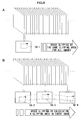
- Time clipping includes two types of methods.
- the first method is to create a moving image file including plurality of images generated in a predetermined period during the period of time-lapse photography.
- the second method is to create a moving image file including plurality of images which are picked at every predetermined time interval from plurality of images generated during the period of time-lapse photography.
- Fig. 4A is a diagram explaining the first method
- Fig. 4B is a diagram explaining the second method.
- first method as shown in Fig. 4A , plurality of images generated during a predetermined period, which is specified by a method that will be described later, are pulled out from plurality of images generated during the period of time-lapse photography, and a moving image file including the pulled out plurality of images is created.
- second method as shown in Fig. 4B , there is created a moving image file including plurality of images which are picked at every predetermined time interval, which is specified by a method that will be described later, from plurality of images generated during the period of time-lapse photography.
- the computer 170 displays a clipping specification screen shown in Fig. 5A on the monitor 160.
- the user can input the period in which time clipping is performed and the picking interval via the input device 180 so as to specify them.
- the picking interval may not necessarily be even.
- the picking interval may be specified such as every 10 minutes in a first hour, every 20 minutes in a next hour, every 10 minutes in a next hour thereafter, and so on.
- a clipping frame 56-1 is displayed on the time line 50 as shown in Fig. 5B , by which the user may specify an arbitrary period on the time line 50 via the input device 180 as a period to perform time clipping.
- a marking button 57 may be provided instead of the clipping button 56 on the reproduction control part 105. Then the user may specify a desired time by selecting the marking button 57 via the input device 180 during the period of time-lapse photography and after the time-lapse photography is finished. In this case, as shown in Fig. 5C , marks (57-1, 57-2) may be displayed on the time line 50.
- Time clipping is then performed according to the marks.
- another moving image file may be created by pulling out only marked images, or another moving image file may be created by pulling out a few or few tens of images around marked images.
- the user can mark a target image via the input device 180 to thereby perform time clipping around this image.
- Time clipping may be performed automatically according to a state change while monitoring a state of a specimen by the computer 170. Specifically, the state of the specimen is monitored based on images generated in the period of time-lapse photography, and processing similar to that by the marking button 57 explained in (1) - [1] may be performed based on a monitoring result. For example, an intensity ratio in fluorescence of the above-described first fluorescence image and second fluorescence image can be obtained, and a state change of the specimen can be monitored based on this intensity ratio in fluorescence.
- Space clipping is a method to clip an image of a predetermined area from each of plurality of images generated in a predetermined period in the period of time-lapse photography, and generate a moving image file including clipped plurality of images.
- the computer 170 displays a clipping frame 58-1 on a display area as shown in Fig. 6A . Then the user specifies a clipping area on the display area via the input device 180 in one image (first image in the example of Fig. 6A ) among plurality of images generated in the period of time-lapse photography. Then, space clipping is performed by the same clipping area for all the images.
- the user may specify clipping areas (58-2, 58-3, and 58-4) on display areas via the input device 180 in plurality of images (the first image, a middle image, and the last image in the example of Fig. 6B ).
- space clipping is performed by calculating a clipping area in every image by an interpolation method or the like.
- the user can specify a target area as a clipping area via the input device 180 to thereby perform space clipping around this area.
- Space clipping may be performed automatically according to a state change while monitoring a state of a specimen by the computer 1 70.
- the user specifies a clipping area via the input device 180 at the time of starting the time-lapse photography. Then fluorescence intensity distributions of a first fluorescence image and a second fluorescence image generated during the time-lapse photography period thereafter are obtained, and the clipping area specified by the user can be traced based on the fluorescence intensity distributions.
- the user may specify a clipping area via the input device 180 in middle of the time-lapse photography, and thereafter the clipping area may be traced based on an image generated during the time-lapse photography period.
- the time clipping explained in (1) and the space clipping explained in (2) may be performed in combination.
- the space clipping may be performed after the time clipping is performed, or the time clipping may be performed after the space clipping is performed. Further, the time clipping and the space clipping may be performed at the same time. Particularly, when the space clipping is performed after the time clipping is performed, processing by the computer 1 70 can be made lighter.
- the microscope apparatus including a time-lapse imaging unit which captures a specimen repeatedly at predetermined time intervals and generates plurality of images
- pulling out target data can be facilitated by performing at least one of the time clipping and the space clipping on generated data.
- data generated during time-lapse photography can be managed preferably.
- a moving image file generated by performing at least one of the time clipping and the space clipping may be recorded by associating with a moving image file including all the images generated in the period of time-lapse photography. Further, after checking the user's demand, the moving image file generated by performing at least one of the time clipping and the space clipping may be recorded instead of the moving image file including all the images generated in the period of time-lapse photography.
Landscapes
- Multimedia (AREA)
- Engineering & Computer Science (AREA)
- Signal Processing (AREA)
- Physics & Mathematics (AREA)
- Computer Vision & Pattern Recognition (AREA)
- Analytical Chemistry (AREA)
- Chemical & Material Sciences (AREA)
- General Physics & Mathematics (AREA)
- Optics & Photonics (AREA)
- Microscoopes, Condenser (AREA)
- Investigating, Analyzing Materials By Fluorescence Or Luminescence (AREA)
- Image Processing (AREA)
- Studio Devices (AREA)
Applications Claiming Priority (2)
| Application Number | Priority Date | Filing Date | Title |
|---|---|---|---|
| JP2006324602A JP4893275B2 (ja) | 2006-11-30 | 2006-11-30 | 顕微鏡装置 |
| PCT/JP2007/001314 WO2008065751A1 (fr) | 2006-11-30 | 2007-11-29 | Dispositif de microscope |
Publications (2)
| Publication Number | Publication Date |
|---|---|
| EP2085806A1 true EP2085806A1 (de) | 2009-08-05 |
| EP2085806A4 EP2085806A4 (de) | 2011-12-14 |
Family
ID=39467551
Family Applications (1)
| Application Number | Title | Priority Date | Filing Date |
|---|---|---|---|
| EP07828091A Ceased EP2085806A4 (de) | 2006-11-30 | 2007-11-29 | Mikroskopanordnung |
Country Status (5)
| Country | Link |
|---|---|
| US (1) | US8139106B2 (de) |
| EP (1) | EP2085806A4 (de) |
| JP (1) | JP4893275B2 (de) |
| CN (1) | CN101548218B (de) |
| WO (1) | WO2008065751A1 (de) |
Cited By (1)
| Publication number | Priority date | Publication date | Assignee | Title |
|---|---|---|---|---|
| US11302437B2 (en) | 2016-12-09 | 2022-04-12 | Sony Corporation | Information processing device, information processing method and information processing system |
Families Citing this family (24)
| Publication number | Priority date | Publication date | Assignee | Title |
|---|---|---|---|---|
| EP2418473B1 (de) | 2009-04-10 | 2022-01-26 | Nikon Corporation | Vorrichtung zur beobachtung von organismusproben |
| JP5385028B2 (ja) | 2009-07-06 | 2014-01-08 | オリンパス株式会社 | 顕微鏡装置 |
| HUP0900431A2 (en) * | 2009-07-10 | 2011-01-28 | Cryo Innovation Kft | Sample imaging system and pocedure for transmitting imager of cells or tissues located in breeder space towards a data processing device |
| US8564623B2 (en) * | 2009-12-11 | 2013-10-22 | Molecular Devices, Llc | Integrated data visualization for multi-dimensional microscopy |
| WO2011071505A1 (en) * | 2009-12-11 | 2011-06-16 | Mds Analytical Technologies (Us) Inc. | Integrated data visualization for multi-dimensional microscopy |
| WO2011096181A1 (ja) * | 2010-02-03 | 2011-08-11 | 株式会社ニコン | 観察装置及び観察方法 |
| EP2550522B1 (de) | 2010-03-23 | 2016-11-02 | California Institute of Technology | Hochauflösende optofluidische mikroskope für 2d- und 3d-bildgebung |
| WO2012058233A2 (en) | 2010-10-26 | 2012-05-03 | California Institute Of Technology | Scanning projective lensless microscope system |
| US9569664B2 (en) * | 2010-10-26 | 2017-02-14 | California Institute Of Technology | Methods for rapid distinction between debris and growing cells |
| US9643184B2 (en) | 2010-10-26 | 2017-05-09 | California Institute Of Technology | e-Petri dishes, devices, and systems having a light detector for sampling a sequence of sub-pixel shifted projection images |
| JP5738580B2 (ja) | 2010-12-03 | 2015-06-24 | オリンパス株式会社 | 顕微鏡装置および観察方法 |
| WO2012119094A2 (en) | 2011-03-03 | 2012-09-07 | California Institute Of Technology | Light guided pixel |
| JP5732353B2 (ja) * | 2011-08-31 | 2015-06-10 | 株式会社キーエンス | 拡大観察装置、拡大観察方法および拡大観察プログラム |
| US9247098B2 (en) | 2013-04-09 | 2016-01-26 | Here Global B.V. | Automatic time lapse capture |
| JP6135391B2 (ja) * | 2013-08-16 | 2017-05-31 | ソニー株式会社 | 撮像装置、画像処理装置、および画像処理方法、並びにプログラム |
| JP5817858B2 (ja) * | 2014-01-30 | 2015-11-18 | カシオ計算機株式会社 | 画像処理装置、画像処理方法、及びプログラム |
| US9503631B2 (en) * | 2014-02-12 | 2016-11-22 | Lg Electronics Inc. | Mobile terminal and control method thereof for displaying image cluster differently in an image gallery mode |
| US9277123B2 (en) * | 2014-05-30 | 2016-03-01 | Apple Inc. | Systems and methods for exposure metering for timelapse video |
| US9992443B2 (en) | 2014-05-30 | 2018-06-05 | Apple Inc. | System and methods for time lapse video acquisition and compression |
| JP6488570B2 (ja) * | 2014-06-30 | 2019-03-27 | カシオ計算機株式会社 | 撮影装置、撮影方法及びプログラム |
| US9426409B2 (en) | 2014-09-30 | 2016-08-23 | Apple Inc. | Time-lapse video capture with optimal image stabilization |
| WO2017057077A1 (ja) * | 2015-09-29 | 2017-04-06 | 富士フイルム株式会社 | 標的細胞の識別方法、及び標的細胞識別装置 |
| JP6957131B2 (ja) * | 2016-03-01 | 2021-11-02 | オリンパス株式会社 | 情報端末装置、撮像装置、画像情報処理システム及び画像情報処理方法 |
| CN110612345B (zh) | 2017-05-09 | 2023-04-28 | 仪景通株式会社 | 图像再现装置和观察系统 |
Family Cites Families (12)
| Publication number | Priority date | Publication date | Assignee | Title |
|---|---|---|---|---|
| US4354114A (en) * | 1979-10-09 | 1982-10-12 | Karnaukhov Valery N | Apparatus for investigation of fluorescence characteristics of microscopic objects |
| US6313452B1 (en) * | 1998-06-10 | 2001-11-06 | Sarnoff Corporation | Microscopy system utilizing a plurality of images for enhanced image processing capabilities |
| GB2343807A (en) * | 1998-11-11 | 2000-05-17 | Isis Innovation | Retrieving video data specified by parameters from a remote source |
| JP2002033997A (ja) * | 2000-07-18 | 2002-01-31 | Nec Corp | タイムラプス記録再生装置 |
| US20030149983A1 (en) * | 2002-02-06 | 2003-08-07 | Markel Steven O. | Tracking moving objects on video with interactive access points |
| JP2004309719A (ja) * | 2003-04-04 | 2004-11-04 | Olympus Corp | 顕微鏡システム、顕微鏡システムの制御方法、及び制御プログラム |
| JP4740554B2 (ja) | 2004-05-12 | 2011-08-03 | オリンパス株式会社 | 培養顕微鏡装置 |
| JP4664599B2 (ja) * | 2004-01-15 | 2011-04-06 | オリンパス株式会社 | 顕微鏡装置 |
| DE102005023855A1 (de) * | 2004-05-26 | 2006-01-26 | Olympus Corporation | Kulturmikroskop und Computerprogramm zur Steuerung des Kulturmikroskops |
| JP4928081B2 (ja) * | 2005-02-03 | 2012-05-09 | オリンパス株式会社 | 顕微鏡用撮像装置、記録制御方法、および記録制御プログラム |
| JP5058444B2 (ja) | 2005-02-10 | 2012-10-24 | オリンパス株式会社 | 顕微鏡写真装置および顕微鏡写真装置制御方法 |
| JP2006259701A (ja) * | 2005-02-16 | 2006-09-28 | Nikon Corp | 間欠撮影装置とこれを有する顕微鏡システム |
-
2006
- 2006-11-30 JP JP2006324602A patent/JP4893275B2/ja active Active
-
2007
- 2007-11-29 EP EP07828091A patent/EP2085806A4/de not_active Ceased
- 2007-11-29 WO PCT/JP2007/001314 patent/WO2008065751A1/ja not_active Ceased
- 2007-11-29 CN CN2007800441765A patent/CN101548218B/zh active Active
-
2009
- 2009-05-27 US US12/453,924 patent/US8139106B2/en active Active
Cited By (1)
| Publication number | Priority date | Publication date | Assignee | Title |
|---|---|---|---|---|
| US11302437B2 (en) | 2016-12-09 | 2022-04-12 | Sony Corporation | Information processing device, information processing method and information processing system |
Also Published As
| Publication number | Publication date |
|---|---|
| JP4893275B2 (ja) | 2012-03-07 |
| WO2008065751A1 (fr) | 2008-06-05 |
| CN101548218A (zh) | 2009-09-30 |
| CN101548218B (zh) | 2012-07-04 |
| JP2008139488A (ja) | 2008-06-19 |
| US20090237502A1 (en) | 2009-09-24 |
| US8139106B2 (en) | 2012-03-20 |
| EP2085806A4 (de) | 2011-12-14 |
Similar Documents
| Publication | Publication Date | Title |
|---|---|---|
| US8139106B2 (en) | Microscope apparatus | |
| CN101542353B (zh) | 图像处理装置、图像处理方法和观察系统 | |
| EP1691230B2 (de) | Lichtmikrografievorrichtung und Steuerverfahren dafür | |
| US20050282268A1 (en) | Culture microscope and computer program controlling culture microscope | |
| US8014579B2 (en) | Microscope system and method for synthesizing microscopic images | |
| JP2008052227A (ja) | 観察装置 | |
| JP2008139487A (ja) | 顕微鏡装置 | |
| CN101351736A (zh) | 发光测量装置及发光测量方法 | |
| JP5365691B2 (ja) | 生体試料観察装置 | |
| JP5039355B2 (ja) | 自動培養装置 | |
| US8411357B2 (en) | Motor-operated microscope system and software for controlling motor-operated microscopes | |
| JP2007114742A (ja) | 観察装置 | |
| US20100053736A1 (en) | Confocal microscope apparatus | |
| JP6441317B2 (ja) | 統合された制御を使用するサンプル画像取り込みのためのシステム及び方法 | |
| JP2008139489A (ja) | 顕微鏡装置 | |
| WO2013005765A1 (ja) | 顕微鏡装置 | |
| JP2009027948A (ja) | 培養装置 | |
| Paddock | A brief history of time-lapse | |
| JP2012194517A (ja) | 画像表示装置、観察装置、表示プログラム、画像表示方法、および観察制御方法 | |
| WO2024075732A1 (ja) | タイムラプス撮影機能付き培養装置および培養方法 | |
| JP2009169235A5 (de) | ||
| JPWO2017109983A1 (ja) | 微弱発光試料の解析方法及び解析システム |
Legal Events
| Date | Code | Title | Description |
|---|---|---|---|
| PUAI | Public reference made under article 153(3) epc to a published international application that has entered the european phase |
Free format text: ORIGINAL CODE: 0009012 |
|
| 17P | Request for examination filed |
Effective date: 20090514 |
|
| AK | Designated contracting states |
Kind code of ref document: A1 Designated state(s): AT BE BG CH CY CZ DE DK EE ES FI FR GB GR HU IE IS IT LI LT LU LV MC MT NL PL PT RO SE SI SK TR |
|
| DAX | Request for extension of the european patent (deleted) | ||
| RAP1 | Party data changed (applicant data changed or rights of an application transferred) |
Owner name: NIKON CORPORATION |
|
| A4 | Supplementary search report drawn up and despatched |
Effective date: 20111114 |
|
| RIC1 | Information provided on ipc code assigned before grant |
Ipc: H04N 5/262 20060101ALI20111108BHEP Ipc: G02B 21/00 20060101ALI20111108BHEP Ipc: H04N 5/915 20060101ALI20111108BHEP Ipc: G11B 27/031 20060101ALI20111108BHEP Ipc: G02B 21/36 20060101AFI20111108BHEP Ipc: H04N 1/21 20060101ALI20111108BHEP Ipc: G02B 21/16 20060101ALI20111108BHEP Ipc: H04N 5/225 20060101ALI20111108BHEP |
|
| 17Q | First examination report despatched |
Effective date: 20150205 |
|
| RAP1 | Party data changed (applicant data changed or rights of an application transferred) |
Owner name: NIKON CORPORATION |
|
| APBK | Appeal reference recorded |
Free format text: ORIGINAL CODE: EPIDOSNREFNE |
|
| APBN | Date of receipt of notice of appeal recorded |
Free format text: ORIGINAL CODE: EPIDOSNNOA2E |
|
| APBR | Date of receipt of statement of grounds of appeal recorded |
Free format text: ORIGINAL CODE: EPIDOSNNOA3E |
|
| APAF | Appeal reference modified |
Free format text: ORIGINAL CODE: EPIDOSCREFNE |
|
| REG | Reference to a national code |
Ref country code: DE Ref legal event code: R003 |
|
| APBT | Appeal procedure closed |
Free format text: ORIGINAL CODE: EPIDOSNNOA9E |
|
| STAA | Information on the status of an ep patent application or granted ep patent |
Free format text: STATUS: THE APPLICATION HAS BEEN REFUSED |
|
| 18R | Application refused |
Effective date: 20200214 |