EP2086087A2 - Als Bus-Kuppelschalter bei der Verteilung von elektrischem Strom verwendete elektronische Ladungssteuerungseinheit (ELCU) - Google Patents
Als Bus-Kuppelschalter bei der Verteilung von elektrischem Strom verwendete elektronische Ladungssteuerungseinheit (ELCU) Download PDFInfo
- Publication number
- EP2086087A2 EP2086087A2 EP09150809A EP09150809A EP2086087A2 EP 2086087 A2 EP2086087 A2 EP 2086087A2 EP 09150809 A EP09150809 A EP 09150809A EP 09150809 A EP09150809 A EP 09150809A EP 2086087 A2 EP2086087 A2 EP 2086087A2
- Authority
- EP
- European Patent Office
- Prior art keywords
- electrical power
- pdp
- elcu
- power
- current
- Prior art date
- Legal status (The legal status is an assumption and is not a legal conclusion. Google has not performed a legal analysis and makes no representation as to the accuracy of the status listed.)
- Withdrawn
Links
Images


Classifications
-
- H—ELECTRICITY
- H02—GENERATION; CONVERSION OR DISTRIBUTION OF ELECTRIC POWER
- H02J—ELECTRIC POWER NETWORKS; CIRCUIT ARRANGEMENTS OR SYSTEMS FOR SUPPLYING OR DISTRIBUTING ELECTRIC POWER; SYSTEMS FOR STORING ELECTRIC ENERGY
- H02J9/00—Circuit arrangements for emergency or stand-by power supply, e.g. for emergency lighting
- H02J9/04—Circuit arrangements for emergency or stand-by power supply, e.g. for emergency lighting in which the distribution system is disconnected from the normal source and connected to a standby source
- H02J9/06—Circuit arrangements for emergency or stand-by power supply, e.g. for emergency lighting in which the distribution system is disconnected from the normal source and connected to a standby source with automatic change-over, e.g. UPS systems
-
- H—ELECTRICITY
- H02—GENERATION; CONVERSION OR DISTRIBUTION OF ELECTRIC POWER
- H02H—EMERGENCY PROTECTIVE CIRCUIT ARRANGEMENTS
- H02H7/00—Emergency protective circuit arrangements specially adapted for specific types of electric machines or apparatus or for sectionalised protection of cable or line systems, and effecting automatic switching in the event of an undesired change from normal working conditions
- H02H7/26—Sectionalised protection of cable or line systems, e.g. for disconnecting a section on which a short-circuit, earth fault, or arc discharge has occured
Definitions
- the present invention relates to electrical power distribution systems, and more particularly, to the control of bus tie breakers in electrical power distribution systems.
- BTCs Bus Tie Contactors
- Figure 1 shows a conventional electrical power distribution system 10 in accordance with the prior art.
- Figure 1 shows the electrical power system 10 during normal mode of operation.
- Two electrical power sources 12, 14 are connected to electrical loads 16, 18 via distribution buses 24 and 26 located in power distribution panels 20, 22 respectively.
- the power sources 12, 14 may be, for example, electrical generators.
- Power bus bars 24, 26 connect the electrical power sources to the plurality of electrical loads 16, 18 through a plurality of Electrical Load Control Units, e.g., (ELCUs) 28, 30.
- the ELCUs 28, 30 as well as circuit breakers (not shown) may be used to provide line protection for each load 16, 18.
- bus tie contactors (BTCs) 32, 34 are used to allow transfer of, or to isolate electrical power between, power bus bars 24, 26.
- the transfer may be performed by connecting ("tying") electrical power buses together through electrical connection 36, which may comprise a cable.
- the BTCs 32, 34 may be used to reconfigure the system under certain fault conditions to ensure the availability of power on both buses 24 and 26.
- Electrical power system 10 may be a variable frequency or a constant frequency power system.
- the power sources 12, 14 are not synchronized and power buses cannot be tied together.
- each power source 12, 14 delivers power to its own bus 24, 26 and the BTCs 32, 34 are de-activated (opened) to keep the generator channels separated.
- BTCs 32, 34 may be controlled by control logic in a bus power control unit (BPCU) hereinafter referred to as a CONTROL DEVICE 46, which senses current from current transformers (CTs) 48, 50.
- BPCU bus power control unit
- FIG. 2 shows the state of the electrical power system 10 when the electrical source 12 has failed.
- Generator control units (GCUs) 38, 40 may be used to detect the failure of either the electrical source 12 or 14 respectively.
- GCU 38 Upon failure of electrical source 12, the associated GCU 38 will isolate the electrical source 12 by commanding a generator control breaker (GCB) 42 to open, thereby removing the power source 12 from the bus bar 24.
- GEB generator control breaker
- the BTCs will be activated (closed) by signals from the CONTROL DEVICE 46, or by GCUs 38 and 40, as shown in Figure 2 .
- the unpowered bus bar 24 will be cross-fed by the active power source 14 which may supply the total power to both power bus bars 24, 26.
- the associated GCU 40 may sense the failure and may command GCB 44 to open and thereby removing the power source 14 from the bus bar 26.
- CONTROL DEVICE 46 would also close both BTCs 32, 34 so that power source 12 may supply power to both power bus bars 24, 26.
- FIG 3 shows the electrical power system 10 in the situation where there has been a subsequent power bus fault.
- power bus bar 24 has failed short-circuited; this led to the disconnection of power source 12 from the bus by its GCU.
- the BTCs 32, 34 may once again be de-activated (opened) to isolate the fault.
- Power bus bar 24 may be deenergized. The power to all loads 16 supplied by power bus bar 24 will be lost.
- the electrical power system 10 has its electrical power generators operating at Constant Frequency (CF) such as that found on the Boeing 747, the system may operate with BTCs 32, 34 closed.
- power sources 12, 14 share the burden of supplying power to the downstream loads 16, 18.
- power source faults and power bus faults may be handled in a manner similar to the VF power system shown in Figures 1 and 3 .
- Case 1 each power source feeds its own bus, where three control algorithms are needed as follows:
- CT current transformers
- the electric power system 10 shown in Figures 1-3 is a relatively simple example since it addresses a system including only two generating source.
- the electrical power system may be more complex, including multiple generators and external power sources.
- the principle of control remains the same; however, the control algorithms become even more complex.
- an electrical power distribution system comprises a first primary distribution panel (PDP) connected to a first source of electrical power; a second PDP connected to a second source of electrical power, the second PDP being connected to the first PDP by a 'cross-tie' conductor; a first electronic load control unit (ELCU) receiving signals corresponding to the flow of current in the cross-tie conductor through the first PDP; a second ELCU receiving signals corresponding to the flow of current in the cross-tie conductor through the second PDP; and the first and second ELCUs responding to a fault condition in the conductor by interrupting the flow of electrical power between the first and second PDPs.
- PDP primary distribution panel
- a second PDP connected to a second source of electrical power
- the second PDP being connected to the first PDP by a 'cross-tie' conductor
- ELCU electronic load control unit
- an electrical power distribution system comprises first source of electrical power connected to a first primary distribution panel (PDP); a second source of electrical power connected to a second PDP; an electrical load; a first electronic load control unit (ELCU) having a first contactor connected to the first source of electrical power, said first contactor having open and closed modes; a second ELCU having a second contactor connected to the second source of electrical power, said second contactor having open and closed modes; a conductor connected to the second contactor and to the electrical load; and the first ELCU sensing a current in a cross-tie conductor from the first source and in response thereto, opening the first contactor and at least one of the first and second ELCUs closing the second contactor to permit electrical power to flow from the first PDP load said cross-tie conductor.
- PDP primary distribution panel
- a second source of electrical power connected to a second PDP
- an electrical load a first electronic load control unit (ELCU) having a first contactor connected to the first source of electrical power,
- a circuit for protecting an electrical power distribution system comprises first power distribution panel (PDP) connected to a first source of electrical power; a second PDP connected to the first PDP by a conductor; a three phase electrical load connected to the first PDP; a first ELCU receiving signals corresponding to the flow of current through each of the three phases of the three phase electrical load; a second ELCU receiving signals corresponding to the flow of current through the second PDP; and at least one of the first and second ELCUs responding to the detection of a phase imbalance between the phases of current through the three phases by disconnecting the first source of electrical power.
- PDP power distribution panel
- FIG. 1 is a block diagram of an electric power system in accordance with the prior art
- Figure 2 is a block diagram of the electric power system shown in Figure 1 in a first failure mode
- Figure 3 is a block diagram of the electric power system shown in Figure 1 in a second failure mode
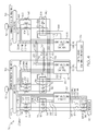
- FIG. 4 is a block diagram of an electric power system in accordance with one embodiment of the present invention.
- the present invention may be advantageously used in electric power systems, including aerospace electrical primary distribution panels (PDP).
- Embodiments of the present invention may provide for the protection of outgoing power to system loads and/or other PDPs that may have lost their dedicated source of power.
- Embodiments of the present invention may use an electric load control unit (ELCU) in place of a Bus Tie Contactor (BTC) commanded contactor.
- ELCU electric load control unit
- BTC Bus Tie Contactor
- Prior art electric power systems relied on BTCs for this protection function.
- embodiments of the present invention may use ELCUs for protection of both electrical load feeders and for bus cross tie feeders. Prior art electric power systems only use ELCUs for electrical load feeder protection.
- Embodiments of the present invention may replace the BTC control algorithms located in the Control Device or GCU with the protection algorithms located as standard features in the ELCU, which eliminates additional wiring and complexity. Embodiments of the present invention also may provide an over current algorithm in the ELCU.
- Prior art power systems used a CONTROL DEVICE having a BTC differential algorithm and had an over current algorithm that was functionally split/implemented between GCUs and BPCU.
- FIG. 4 shows a block diagram of an electric power system 50 which insures the distribution and protection of outgoing power to system loads.
- the electric power system 50 includes first and second power sources 52, 54, which may comprise electrical generators. Each power source 52, 54 may supply electric power to a primary distribution panel (PDP) 56, 58, which in turn may supply electric power to one or more loads 60.
- Loads 60 may comprise three phase loads connected to the PDP 56 by three feeder lines 62, 64 and 66.
- Power from the power sources 52, 54 may be transferred to power bus bars 68, 70 respectively, residing in the PDPs 56, 58.
- Power bus bar 68 may be connected to a first contactor 78 by means of three lines 72, 74 and 76.
- Contactor unit 78 may include three contacts 92, 94 and 96 connected to lines 72, 74 and 76 on an input side and to the feeder line 62, 64 and 66 on the output side.
- a first ELCU 80 may be connected to the first contactor 78 though lines 88 and 90 which may carry controls signals that control the state of contactors 92, 94 and 96.
- First ELCU 80 may also be coupled to the lines 72, 74 and 76 through three current transformers (CT) 82, 84 and 86, which sense the current in lines 72, 74 and 76.
- CT current transformers
- first ELCU 80 may be coupled to lines 62, 64 and 66 through CTs 98, 100 and 102, which sense the current in lines 62, 64 and 66.
- First ELCU 80 (as well as second and third ELCUs 104, 106 described below) may be a conventional ELCU. It will be appreciated that ELCUs are common devices used in the aerospace industry for protecting electrical feeders.
- ELCU 80 may comprise a power contactor, control logic (using discrete components, application specific integrated circuitry or microprocessor) and current sensors (e.g. current transformers or Hall Effect sensors).
- ELCU's commonly are provided with built-in "intelligence" features such as:
- the function of the first ELCU 80 may be to control the states of the contactor 78 so that power to the loads 60 may be switched on or off depending on processing the current information sensed by CTs, 82, 84, 86, 98, 100 and 102.
- Electric power system 50 also may include second and third ELCUs 104, 106 connected to a control device 108.
- Device 108 may be a CONTROL DEVICE or GCU for the purpose of the control of the status (ON/OFF) of the ELCUs, i.e., detection of failure conditions of the power sources that may require the closure of the two ELCUs that operate now, as proposed by the present invention in the role of BTCs.
- Second ELCU 104 may be located in PDP 56 and may control the state of contactor 116 through control lines 118 and 120.
- Second contactor 116 includes contacts 110, 112 and 114 and may be connected to the first power bus 68 through lines 122, 124 and 126.
- Second ELCU 104 may be coupled to L BUS 230VAC via lines 122, 124 and 126 and receive line current information through Current Transformers CTs 128 130 and 132.
- Third ELCU 106 may be located in PDP 58 and may control the state of contactor 140 through control lines 142 and 144.
- Third contactor 140 may includes contacts 134, 136 and 138 and may be connected to the second power bus 70 through lines 146, 148 and 150.
- Third ELCU 106 may be coupled to R BUS 230VAC bus via lines 146, 148 and 150 and receive line current information through Current Transformers - CTs 152, 154 and 156.
- the lower side of contactor 116 may be connected, through bus cross-tie feeders 158, 160 and 162, to the lower side of contactor 140.
- the second ELCU 104 may sense the state of CTs 152, 154 and 156 in the PDP 58 through lines 164, 166 and 168.
- the third ELCU 106 may sense the state of CTs 128, 130 and 132 in the PDP56 through lines 170, 172 and 174. It is noted that, as shown in Figure 4 , the outputs of the CTs 128, 130, 132, 152, 154 and 156 may be connected differentially, allowing their use for differential protection implementation and over current protection.
- second and third ELCUs 104, 106 and control device 108 may be similar to the operation of the CONTROL DEVICE 46 and BTCs 32, 34 as shown in Figures 1-3 .
- second and third ELCUs contactors 104 and 106 are open. In this state the two PDPs 56, 58 may operate independently.
- control device 108 may sense this condition and close ELCU contactors 116 and 140. In this way, power from source 54 may directed across feeders 158, 160 and 162 to PDP 52 where it can supply electrical power to the load 60.
- ECLUs 80, 104 and 106 along with the control device 108 may be provided with the following algorithms as standard features: algorithm (a) differential protection to protect against faults to ground; algorithm (b) over current protection, and algorithm (c) missing phase protection.
- algorithm (a) may replace the prior art protection algorithm that inhibits the closure of the BTC in the case where a fault to ground is detected on the feeders 158, 160 and 162 connecting power bus bar 68 to power bus bar 70 for circuits where each power source feeds its own bus.
- Algorithm (b) may replace the prior art analysis algorithm for the isolation of the cause of the failure described above, as well as the prior art control algorithm used to isolate an over current fault to the specific bus in cases where one power source feeds both busses.
- Algorithm (c) may enhance the protection capabilities of the control due to the fact that it does not permit operation of the loads connected to a power bus bar with a missing phase.
- the present invention may provide a solution for the implementation of the bus bar connections via the use of ELCUs with integral control instead of classic contactors with control allocated to GCUs or CONTROL DEVICE.
- the present invention takes full advantage of the features already built in as part of ELCU design to simplify the architectures for an aircraft electric power system, and to implicitly optimize the control logic during normal and abnormal modes of operation.
- the use of a common device, the ELCU commanded contactor in place of a BTC allows the achievement of a modular design. As such a single device, the ELCU can be used to protect all output feeders from a PDP; both the supply feeders and the bus cross tie feeders.
- the present invention can allow a modular implementation of power distribution panel by using common devices for both, power distribution and cross tie connections.
- the present invention also can allow for the simplification of control algorithms located in GCUs and CONTROL DEVICEs including the downgrading of the redundancy levels required for implementation of this hazardous functionality.
- the present invention can enhance the electrical power system protections by adding the missing phase protection of a bus bar.
Landscapes
- Business, Economics & Management (AREA)
- Emergency Management (AREA)
- Engineering & Computer Science (AREA)
- Power Engineering (AREA)
- Supply And Distribution Of Alternating Current (AREA)
Applications Claiming Priority (1)
| Application Number | Priority Date | Filing Date | Title |
|---|---|---|---|
| US12/019,474 US7626798B2 (en) | 2008-01-24 | 2008-01-24 | Electronic load control unit (ELCU) used as bus tie breaker in electrical power distribution systems |
Publications (1)
| Publication Number | Publication Date |
|---|---|
| EP2086087A2 true EP2086087A2 (de) | 2009-08-05 |
Family
ID=40651629
Family Applications (1)
| Application Number | Title | Priority Date | Filing Date |
|---|---|---|---|
| EP09150809A Withdrawn EP2086087A2 (de) | 2008-01-24 | 2009-01-16 | Als Bus-Kuppelschalter bei der Verteilung von elektrischem Strom verwendete elektronische Ladungssteuerungseinheit (ELCU) |
Country Status (2)
| Country | Link |
|---|---|
| US (1) | US7626798B2 (de) |
| EP (1) | EP2086087A2 (de) |
Cited By (3)
| Publication number | Priority date | Publication date | Assignee | Title |
|---|---|---|---|---|
| CN101917018A (zh) * | 2010-07-28 | 2010-12-15 | 南京高传机电自动控制设备有限公司 | 大功率双馈风力发电机的组合控制柜 |
| EP2600478A3 (de) * | 2011-12-02 | 2017-06-14 | Hamilton Sundstrand Corporation | Vorrichtung für wechselseitige Kommunikation zwischen Kanälen eines Halbleiterleistungscontrollers |
| EP3955407A1 (de) * | 2020-08-12 | 2022-02-16 | CAF Power & Automation, S.L.U. | Redundantes versorgungssystem |
Families Citing this family (17)
| Publication number | Priority date | Publication date | Assignee | Title |
|---|---|---|---|---|
| US8050806B2 (en) * | 2007-03-21 | 2011-11-01 | Honeywell International Inc. | Ground fault interruption using DSP based SSPC module |
| US8148848B2 (en) * | 2008-01-24 | 2012-04-03 | Honeywell International, Inc. | Solid state power controller (SSPC) used as bus tie breaker in electrical power distribution systems |
| US20090244817A1 (en) * | 2008-04-01 | 2009-10-01 | Moyer Anthony R | Electrical Distribution System |
| FR2930084B1 (fr) * | 2008-04-09 | 2012-06-08 | Thales Sa | Procede de gestion d'un reseau electrique |
| US9184592B2 (en) * | 2008-08-05 | 2015-11-10 | Lennox Industries Inc. | Utility-interactive inverter system architecture and method of operation thereof |
| US8604630B2 (en) * | 2010-06-01 | 2013-12-10 | Caterpillar Inc. | Power distribution system having priority load control |
| US8614870B2 (en) * | 2011-01-14 | 2013-12-24 | Hamilton Sundstrand Corporation | Active transient current control in electronic circuit breakers |
| US9172272B2 (en) * | 2012-02-17 | 2015-10-27 | Sikorsky Aircraft Corporation | Electrical power distribution system |
| US8564914B2 (en) | 2012-02-21 | 2013-10-22 | Sikorsky Aircraft Corporation | Fault clearing without a DC backup power source |
| US9197056B2 (en) * | 2012-06-11 | 2015-11-24 | Honeywell International Inc. | Solid state power control system for aircraft high voltage DC power distribution |
| US9577432B2 (en) | 2013-08-09 | 2017-02-21 | The Boeing Company | Advanced energy monitoring and control in a complex system |
| CN104167812B (zh) * | 2014-08-26 | 2016-09-21 | 国家电网公司 | 两进一母联自投自复控制系统 |
| FR3055466B1 (fr) * | 2016-08-29 | 2018-09-21 | Schneider Electric Industries Sas | Unite de controle d'un disjoncteur comportant un systeme de gestion d'alimentation electrique et disjoncteur comportant une telle unite |
| CN110635451B (zh) * | 2018-05-31 | 2022-08-09 | 上海航空电器有限公司 | 单通道多电飞机汇流条功率控制器的差动保护结构 |
| CN110556781B (zh) * | 2018-05-31 | 2022-08-12 | 上海航空电器有限公司 | 单通道多电飞机发电机控制器的联接汇流条差动保护功能结构 |
| CN110667866B (zh) * | 2018-07-03 | 2022-09-06 | 上海航空电器有限公司 | 汇流条功率控制器的外部电源电压、过载、频率、缺相保护结构 |
| US11641101B2 (en) * | 2020-04-08 | 2023-05-02 | Hamilton Sundstrand Corporation | Arc fault induced differential protection isolation |
Family Cites Families (11)
| Publication number | Priority date | Publication date | Assignee | Title |
|---|---|---|---|---|
| US4403292A (en) * | 1979-05-30 | 1983-09-06 | Sundstrand Corporation | Control for an electrical generating and distribution system, and method of operation |
| IL59777A (en) | 1980-04-04 | 1983-05-15 | Israel Aircraft Ind Ltd | Temperature-regulated multiplebattery charging system |
| US5422778A (en) * | 1993-07-28 | 1995-06-06 | Sundstrand Corporation | Protection system for controller and control wiring induced under voltage faults in an electric power generating system |
| US5594285A (en) * | 1993-08-27 | 1997-01-14 | Sundstrand Corporation | Power distribution center |
| US5715124A (en) * | 1996-04-08 | 1998-02-03 | Sundstrand Corporation | System and method of isolation for detecting a passive protective function failure for an electric power generating system |
| US5764502A (en) * | 1996-05-28 | 1998-06-09 | Sundstrand Corporation | Integrated electric power system |
| WO1998034318A1 (en) | 1997-01-31 | 1998-08-06 | Sundstrand Corporation | System and method of radio frequency control for aircraft electric power distribution contactors |
| US6369549B1 (en) * | 1998-10-05 | 2002-04-09 | Ford Global Tech., Inc. | Motor vehicle electrical system with multiple generators |
| US6320732B1 (en) * | 1999-07-15 | 2001-11-20 | Square D Company | Electrical power distribution control system with dual voltage sources |
| US7177125B2 (en) | 2003-02-12 | 2007-02-13 | Honeywell International Inc. | Arc fault detection for SSPC based electrical power distribution systems |
| US7400065B2 (en) * | 2004-08-24 | 2008-07-15 | Honeywell International Inc. | Electrical power distribution system and method with active load control |
-
2008
- 2008-01-24 US US12/019,474 patent/US7626798B2/en not_active Expired - Fee Related
-
2009
- 2009-01-16 EP EP09150809A patent/EP2086087A2/de not_active Withdrawn
Cited By (4)
| Publication number | Priority date | Publication date | Assignee | Title |
|---|---|---|---|---|
| CN101917018A (zh) * | 2010-07-28 | 2010-12-15 | 南京高传机电自动控制设备有限公司 | 大功率双馈风力发电机的组合控制柜 |
| CN101917018B (zh) * | 2010-07-28 | 2012-10-03 | 南京高传机电自动控制设备有限公司 | 大功率双馈风力发电机的组合控制柜 |
| EP2600478A3 (de) * | 2011-12-02 | 2017-06-14 | Hamilton Sundstrand Corporation | Vorrichtung für wechselseitige Kommunikation zwischen Kanälen eines Halbleiterleistungscontrollers |
| EP3955407A1 (de) * | 2020-08-12 | 2022-02-16 | CAF Power & Automation, S.L.U. | Redundantes versorgungssystem |
Also Published As
| Publication number | Publication date |
|---|---|
| US20090190279A1 (en) | 2009-07-30 |
| US7626798B2 (en) | 2009-12-01 |
Similar Documents
| Publication | Publication Date | Title |
|---|---|---|
| US7626798B2 (en) | Electronic load control unit (ELCU) used as bus tie breaker in electrical power distribution systems | |
| US8148848B2 (en) | Solid state power controller (SSPC) used as bus tie breaker in electrical power distribution systems | |
| US7117105B2 (en) | Method and apparatus for ground fault protection | |
| WO2008134126A1 (en) | Transfer switch system with neutral current management | |
| US10804696B2 (en) | Power distribution system and method | |
| US9969341B2 (en) | Assistance device and method for a power generation system of an aircraft | |
| EP2852020B1 (de) | Energieverteilungsarchitektur und Flugzeug mit der Energieverteilungsarchitektur | |
| JP4731403B2 (ja) | 総合後備保護機能付き母線保護継電装置 | |
| JP5678537B2 (ja) | 航空機用静止型電源装置ユニット | |
| JP7347952B2 (ja) | 保護装置 | |
| JP2008220136A (ja) | 配電系統の保護継電システム | |
| US12294215B2 (en) | Redundant power supply, in particular for data centers, and method and computer program for the operation thereof | |
| EP2651026B1 (de) | Automatische Fehlerisolierungsmethodologie | |
| US8564420B2 (en) | Control module with connection devices for connection to connection terminals of a load feeder and load feeder | |
| US9331470B1 (en) | Line side circuit protection system | |
| US11929617B2 (en) | Dynamic electrical load control | |
| US12206241B2 (en) | Redundant power supply, in particular for data centers, and method and computer program for the operation thereof | |
| JP3964601B2 (ja) | 保護システム | |
| JP2009055731A (ja) | スポットネットワーク受電設備の自動復電システム | |
| JPH0245419B2 (de) | ||
| JP2001025157A (ja) | 受変電設備の保護方式 | |
| JPS6026491Y2 (ja) | 母線保護継電装置 | |
| JPH0119207B2 (de) | ||
| JPS63213414A (ja) | 母線保護装置 | |
| JP2003158819A (ja) | 保護継電装置 |
Legal Events
| Date | Code | Title | Description |
|---|---|---|---|
| PUAI | Public reference made under article 153(3) epc to a published international application that has entered the european phase |
Free format text: ORIGINAL CODE: 0009012 |
|
| 17P | Request for examination filed |
Effective date: 20090116 |
|
| AK | Designated contracting states |
Kind code of ref document: A2 Designated state(s): AT BE BG CH CY CZ DE DK EE ES FI FR GB GR HR HU IE IS IT LI LT LU LV MC MK MT NL NO PL PT RO SE SI SK TR |
|
| AX | Request for extension of the european patent |
Extension state: AL BA RS |
|
| RAP1 | Party data changed (applicant data changed or rights of an application transferred) |
Owner name: HONEYWELL INTERNATIONAL INC. |
|
| STAA | Information on the status of an ep patent application or granted ep patent |
Free format text: STATUS: THE APPLICATION HAS BEEN WITHDRAWN |
|
| 18W | Application withdrawn |
Effective date: 20170406 |