EP2086305A2 - Élément à dissipation de chaleur et dissipateur de chaleur en disposant - Google Patents
Élément à dissipation de chaleur et dissipateur de chaleur en disposant Download PDFInfo
- Publication number
- EP2086305A2 EP2086305A2 EP08153333A EP08153333A EP2086305A2 EP 2086305 A2 EP2086305 A2 EP 2086305A2 EP 08153333 A EP08153333 A EP 08153333A EP 08153333 A EP08153333 A EP 08153333A EP 2086305 A2 EP2086305 A2 EP 2086305A2
- Authority
- EP
- European Patent Office
- Prior art keywords
- heat
- dissipating
- substrate
- dissipating element
- extending arm
- Prior art date
- Legal status (The legal status is an assumption and is not a legal conclusion. Google has not performed a legal analysis and makes no representation as to the accuracy of the status listed.)
- Granted
Links
Images





Classifications
-
- F—MECHANICAL ENGINEERING; LIGHTING; HEATING; WEAPONS; BLASTING
- F21—LIGHTING
- F21V—FUNCTIONAL FEATURES OR DETAILS OF LIGHTING DEVICES OR SYSTEMS THEREOF; STRUCTURAL COMBINATIONS OF LIGHTING DEVICES WITH OTHER ARTICLES, NOT OTHERWISE PROVIDED FOR
- F21V29/00—Protecting lighting devices from thermal damage; Cooling or heating arrangements specially adapted for lighting devices or systems
- F21V29/50—Cooling arrangements
- F21V29/70—Cooling arrangements characterised by passive heat-dissipating elements, e.g. heat-sinks
- F21V29/74—Cooling arrangements characterised by passive heat-dissipating elements, e.g. heat-sinks with fins or blades
- F21V29/77—Cooling arrangements characterised by passive heat-dissipating elements, e.g. heat-sinks with fins or blades with essentially identical diverging planar fins or blades, e.g. with fan-like or star-like cross-section
- F21V29/773—Cooling arrangements characterised by passive heat-dissipating elements, e.g. heat-sinks with fins or blades with essentially identical diverging planar fins or blades, e.g. with fan-like or star-like cross-section the planes containing the fins or blades having the direction of the light emitting axis
-
- F—MECHANICAL ENGINEERING; LIGHTING; HEATING; WEAPONS; BLASTING
- F21—LIGHTING
- F21V—FUNCTIONAL FEATURES OR DETAILS OF LIGHTING DEVICES OR SYSTEMS THEREOF; STRUCTURAL COMBINATIONS OF LIGHTING DEVICES WITH OTHER ARTICLES, NOT OTHERWISE PROVIDED FOR
- F21V29/00—Protecting lighting devices from thermal damage; Cooling or heating arrangements specially adapted for lighting devices or systems
- F21V29/50—Cooling arrangements
- F21V29/70—Cooling arrangements characterised by passive heat-dissipating elements, e.g. heat-sinks
- F21V29/74—Cooling arrangements characterised by passive heat-dissipating elements, e.g. heat-sinks with fins or blades
- F21V29/76—Cooling arrangements characterised by passive heat-dissipating elements, e.g. heat-sinks with fins or blades with essentially identical parallel planar fins or blades, e.g. with comb-like cross-section
-
- F—MECHANICAL ENGINEERING; LIGHTING; HEATING; WEAPONS; BLASTING
- F21—LIGHTING
- F21V—FUNCTIONAL FEATURES OR DETAILS OF LIGHTING DEVICES OR SYSTEMS THEREOF; STRUCTURAL COMBINATIONS OF LIGHTING DEVICES WITH OTHER ARTICLES, NOT OTHERWISE PROVIDED FOR
- F21V29/00—Protecting lighting devices from thermal damage; Cooling or heating arrangements specially adapted for lighting devices or systems
- F21V29/50—Cooling arrangements
- F21V29/70—Cooling arrangements characterised by passive heat-dissipating elements, e.g. heat-sinks
- F21V29/74—Cooling arrangements characterised by passive heat-dissipating elements, e.g. heat-sinks with fins or blades
- F21V29/77—Cooling arrangements characterised by passive heat-dissipating elements, e.g. heat-sinks with fins or blades with essentially identical diverging planar fins or blades, e.g. with fan-like or star-like cross-section
-
- H—ELECTRICITY
- H10—SEMICONDUCTOR DEVICES; ELECTRIC SOLID-STATE DEVICES NOT OTHERWISE PROVIDED FOR
- H10W—GENERIC PACKAGES, INTERCONNECTIONS, CONNECTORS OR OTHER CONSTRUCTIONAL DETAILS OF DEVICES COVERED BY CLASS H10
- H10W40/00—Arrangements for thermal protection or thermal control
- H10W40/20—Arrangements for cooling
- H10W40/22—Arrangements for cooling characterised by their shape, e.g. having conical or cylindrical projections
- H10W40/226—Arrangements for cooling characterised by their shape, e.g. having conical or cylindrical projections characterised by projecting parts, e.g. fins to increase surface area
-
- F—MECHANICAL ENGINEERING; LIGHTING; HEATING; WEAPONS; BLASTING
- F21—LIGHTING
- F21Y—INDEXING SCHEME ASSOCIATED WITH SUBCLASSES F21K, F21L, F21S and F21V, RELATING TO THE FORM OR THE KIND OF THE LIGHT SOURCES OR OF THE COLOUR OF THE LIGHT EMITTED
- F21Y2115/00—Light-generating elements of semiconductor light sources
- F21Y2115/10—Light-emitting diodes [LED]
-
- F—MECHANICAL ENGINEERING; LIGHTING; HEATING; WEAPONS; BLASTING
- F28—HEAT EXCHANGE IN GENERAL
- F28F—DETAILS OF HEAT-EXCHANGE AND HEAT-TRANSFER APPARATUS, OF GENERAL APPLICATION
- F28F13/00—Arrangements for modifying heat-transfer, e.g. increasing, decreasing
- F28F13/18—Arrangements for modifying heat-transfer, e.g. increasing, decreasing by applying coatings, e.g. radiation-absorbing, radiation-reflecting; by surface treatment, e.g. polishing
- F28F13/185—Heat-exchange surfaces provided with microstructures or with porous coatings
-
- F—MECHANICAL ENGINEERING; LIGHTING; HEATING; WEAPONS; BLASTING
- F28—HEAT EXCHANGE IN GENERAL
- F28F—DETAILS OF HEAT-EXCHANGE AND HEAT-TRANSFER APPARATUS, OF GENERAL APPLICATION
- F28F3/00—Plate-like or laminated elements; Assemblies of plate-like or laminated elements
- F28F3/02—Elements or assemblies thereof with means for increasing heat-transfer area, e.g. with fins, with recesses, with corrugations
Definitions
- the present invention relates to a heat sink and a heat-dissipating element, and in particular to a heat-dissipating element whose surface is formed with embossed heat-dissipating portions and a heat sink comprising the heat-dissipating element.
- Heat sinks are widely used with heat-generating electronic elements (e.g. CPUs) or lamps (e.g. halogen lamp, LED lamp etc.), to enhance the dissipation of heat.
- the heat sink having heat-dissipating fins is the most popular heat sink.
- Fig. 11 shows a conventional heat sink, in which a plurality of heat-dissipating fins 13 is arranged equidistantly on the top surface 111 of a base 11 by means of welding the solders 12.
- the heat-dissipating fins 13 are used to increase the heat-dissipating area. With the bottom surface 112 of the base 11 contacting a heat source, the base 11 absorbs the heat and transmits the heat rapidly to surfaces 131 of each heat-dissipating fin 13, thereby facilitating the heat dissipation.
- the solder 12 may inhibit the heat transfer between base 11 and heat-dissipating fins 13, which affects the heat-dissipating efficiency of the heat-sink.
- each surface 131 of the heat-dissipating fins 13 is a flat surface.
- the flat surface facilitates heat dissipation, the area of the flat surface can still be insufficient, resulting in an insufficient heat-dissipating effect. Therefore, it is an important issue to develop a heat sink that is capable of dissipating heat efficiently and improve the effect of the heat-dissipating element such as heat-dissipating fins.
- the object of the present invention is to provide a heat-dissipating element whereby the use of solder and the heat transfer loss can be avoided and thus the heat-dissipating efficiency is improved, and a heat sink comprising the heat-dissipating elements.
- the present invention provides a heat-dissipating element in which a plurality of embossed heat-dissipating portions is formed to extend from at least one surface of the heat-dissipating element.
- the present invention further provides a heat sink having heat-dissipating elements, which includes: at least one substrate comprising a base portion and a plurality of extending arms extending from the base portion, insertion slots being provided between each extending arm and two adjacent extending arms; and at least heat-dissipating elements inserted in the corresponding insertion slots of the substrate, the lateral surfaces of the extending arms abutting against the corresponding surfaces of each heat-dissipating element, a plurality of embossed heat-dissipating portions protruding from at least one surface of each heat-dissipating element, which protrudes with its two ends from the top surface and the bottom surface of the substrate.
- the present invention has advantageous effects as follows.
- the surface of the heat-dissipating element is formed with embossed heat-dissipating portions, which increases the surface area of the heat-dissipating element for heat dissipation.
- the present invention can increase the heat-dissipating rate and improve the heat-dissipating effect of the electronic element.
- the insertion slots between each extending arm of the substrate allow the heat-dissipating elements to be inserted therein.
- the two lateral surfaces of each extending arm hold and fix the heat-dissipating elements tightly.
- the present invention can avoid the solders and the heat transfer loss.
- the present invention provides a heat-dissipating element 3.
- a plurality of embossed heat-dissipating portions 311 protrude from at least one surface 31 of the heat-dissipating element 3, thereby increasing the surface area of the heat-dissipating element 3 for heat dissipation and improving the heat-dissipating efficiency.
- Each embossed heat-dissipating portion 311 is formed into a square pyramid.
- the heat-dissipating element 3 is a heat-dissipating fin.
- the plurality of embossed heat-dissipating portions 311 protrude from both surfaces 31, thereby achieving the optimal heat-dissipating effect.
- the heat-dissipating element 3 is a metallic lamp shade, and the embossed heat-dissipating portions 311 are formed on the external surface of the heat-dissipating element 3. In this way, when the metallic lamp shade is used, the surface area for heat dissipation can be further increased, thereby improving the heat-dissipating effect. Forming the plurality of embossed heat-dissipating portions 311 on the surface of the heat-dissipating element 3 can further improve the heat-dissipating efficiency by 5%.
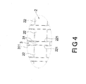
- the present invention further provides a heat sink having heat-dissipating elements, which includes a substrate 2 and a plurality of heat-dissipating elements 3.
- the substrate 2 comprises a base portion 21 and a plurality of extending arms 22.
- the base portion 21 has a top surface 211, a bottom surface 212 and rims 213. Insertion slots 23 are formed between each extending arm 22 and two adjacent extending arms 22.
- the base portion 21 may be a circular plate or a polygonal plate. In the drawings, the base portion is shown as a circular plate.
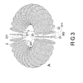
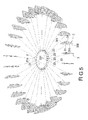
- Each heat-dissipating element 3 is a heat-dissipating fin, which can be formed as a circular plate ( Fig. 2 ) or a polygonal plate ( Fig. 5 ).
- Each heat-dissipating element 3 has a top end 301 and a bottom end 302 opposite to each other, and has two opposite surfaces 31.
- a plurality of embossed heat-dissipating portions 311 protrudes from at least one surface 31 of each heat-dissipating element 3.
- the embossed heat-dissipating portions 311 protrude from the two opposite surfaces 31.
- the embossed heat-dissipating portions 311 of each heat-dissipating element 3 are formed into square pyramids by means of an embossing process.
- Each heat-dissipating element 3 is inserted into the corresponding insertion slot 23 of the substrate 2.
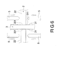
- the lateral 221 surfaces of the extending arms 22 of the substrate 2 abut against the corresponding surfaces 31 of the heat-dissipating elements 3, thereby clamping each heat-dissipating element 3 tightly.
- the top end 301 and the bottom end 302 of each heat-dissipating element 3 protrude from the top surface 211 and the bottom surface 212 of the substrate 2 respectively.
- each heat-dissipating element 3 and the substrate 2 can be achieved by a punching process. In this way, each extending arm 22 of the substrate 2 can be pressed to abut against the surface 31 of the corresponding heat-dissipating element 3 tightly.
- the above-mentioned punching process utilizes a plurality of punches 5 to press the top surface and bottom surface of the extending arm 22 of the substrate 2 in two directions so as to deform the extending arm 22 plastically. In this way, the two lateral surfaces 221 of each extending arm 22 abut against the corresponding surfaces 31 of the heat-dissipating element 3.
- each extending arm 22 of the substrate 2 is formed by means of bending and extending from the rim 213 of the base portion 21.
- a connecting piece 4 can be provided between two heat-dissipating elements 3. Both sides of the connecting piece are integrally connected to the two heat-dissipating elements 3, so that the two heat-dissipating elements 3 can be connected in pairs.
- each heat-dissipating element 3 is inserted into the corresponding insertion slot 23 of the substrate 2.
- the two lateral surfaces 221 of each extending arm 22 of the substrate 2 abut tightly against the two corresponding surfaces 31 of each heat-dissipating element 3.
- each extending arm 22 of the substrate 2 is bent toward the base portion 21.
- each extending arm 22 can be bent to press, so that both lateral surfaces 221 can abut against the corresponding heat-dissipating element 3.
- each heat-dissipating element 3 can be pressed against firmly against the side edge of the substrate 2 firmly.
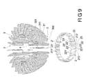
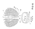
- FIGs. 9 and 10 show a further embodiment of the present invention.
- the difference between this embodiment and the previous embodiments lies in that it includes two symmetrical substrates 2, 2'.
- the two substrates 2, 2' are overlapped each other.
- Each extending arm 22' of one substrate 2' is located to correspond to the insertion slot 23 of the other substrate 2.
- Each extending arm 22, 22' of the two substrates 2, 2' are formed by bending and extending from the rims 213, 213' of the two base portions 21.
- Each heat-dissipating element 3 is disposed in the insertion slots 23, 23' between the two substrates 2, 2'. Similarly, one of the two lateral surfaces 221, 221' forming each extending arm 22, 22' of the two substrates 2, 2' abuts against one of the two surfaces 31 of each heat-dissipating element 3.
- the free ends of the extending arms 22, 22' of the two substrates 2, 2' extend in the same direction.
- the free ends of the extending arms 22, 22' of the two substrates 2, 2' extend in opposite directions.
- the free ends of the extending arms 22, 22' of the two substrates 2, 2' are bent toward the two substrates 21, 21'.
- Each extending arm 22, 22' can be bent to press, so that both lateral surfaces 221, 221' can abut against the corresponding heat-dissipating element 3 tightly. In this way, each heat-dissipating element 3 can be fixed to the side edge of the two substrates 2, 2' firmly.
- a plurality of embossed heat-dissipating portions 311 protrudes from two opposite surfaces 31 of the heat-dissipating element 3, thereby increasing the surface area of the heat-dissipating element 3 for heat dissipation.
- the heat-dissipating element 3 of the present invention can be applied to any kinds of heat sinks, but not limited to the above-mentioned heat sinks.
- the insertion slots 23, 23' between each extending arm 22, 22' of one or two substrates 2, 2' can allow the heat-dissipating element 3 to be inserted therein.
- Two lateral surfaces 221, 221' of each extending arm 22, 22' abut and hold the heat-dissipating element 3 firmly.
- the present invention avoids the use of solders and the heat transfer loss.
- avoiding the use of solders really conforms to the requirements for environmental protection because the solder contains lead while lead-free solders increases the cost.
- the top surface 211 or bottom surface 212 of the substrate 2 can be used to contact a heat-generating element (such as a LED lamp).
- a heat-generating element such as a LED lamp.
- the top end 301 and the bottom end 302 of each heat-dissipating element 3 protrude from the top surface 211, 211' and the bottom surface 212 of one or two substrates 2, 2'. In this way, the cooling/heating airflow can be introduced in or out of the top surfaces 211, 211' and the bottom surface 212 in two directions, thereby achieving the heat-dissipating effect of the electronic element more easily.
- each heat-dissipating element 3 can increase the surface area of each heat-dissipating element 3 for heat dissipation.
- the present invention increases the heat-dissipating rate and the heat-dissipating effect by 5%, thereby enhancing the heat-dissipating effect of the electronic element.
Landscapes
- Engineering & Computer Science (AREA)
- General Engineering & Computer Science (AREA)
- Cooling Or The Like Of Electrical Apparatus (AREA)
- Cooling Or The Like Of Semiconductors Or Solid State Devices (AREA)
Applications Claiming Priority (1)
| Application Number | Priority Date | Filing Date | Title |
|---|---|---|---|
| TW097202290U TWM337229U (en) | 2008-02-01 | 2008-02-01 | Heat dissipating element and heat radiator containing the same |
Publications (3)
| Publication Number | Publication Date |
|---|---|
| EP2086305A2 true EP2086305A2 (fr) | 2009-08-05 |
| EP2086305A3 EP2086305A3 (fr) | 2010-04-14 |
| EP2086305B1 EP2086305B1 (fr) | 2013-03-20 |
Family
ID=39705145
Family Applications (1)
| Application Number | Title | Priority Date | Filing Date |
|---|---|---|---|
| EP08153333A Not-in-force EP2086305B1 (fr) | 2008-02-01 | 2008-03-26 | Dissipateur de chaleur avec éléments à dissipation de chaleur |
Country Status (4)
| Country | Link |
|---|---|
| US (1) | US8230902B2 (fr) |
| EP (1) | EP2086305B1 (fr) |
| JP (1) | JP3144103U (fr) |
| TW (1) | TWM337229U (fr) |
Cited By (4)
| Publication number | Priority date | Publication date | Assignee | Title |
|---|---|---|---|---|
| EP2241390A1 (fr) * | 2009-04-16 | 2010-10-20 | Neng Tyi Precision Industries Co., Ltd. | Procédé de fabrication de radiateurs et son mécanisme d'alignement et déplacement |
| RU2604647C2 (ru) * | 2011-04-29 | 2016-12-10 | Конинклейке Филипс Н.В. | Осветительное сид-устройство с верхней структурой рассеивания тепла |
| EP3502545A4 (fr) * | 2016-08-22 | 2020-03-25 | Ichikoh Industries, Ltd. | Lampe de véhicule |
| EP3663642A1 (fr) * | 2018-12-04 | 2020-06-10 | ZKW Group GmbH | Corps de refroidissement pour un module d'éclairage de véhicule automobile |
Families Citing this family (13)
| Publication number | Priority date | Publication date | Assignee | Title |
|---|---|---|---|---|
| TWI357479B (en) * | 2008-11-28 | 2012-02-01 | Univ Nat Taiwan Science Tech | A thermal module for light source |
| JP5134577B2 (ja) * | 2009-04-03 | 2013-01-30 | 能▲是▼精密工業股▲分▼有限公司 | 放熱器の製造方法、この製造方法に用いる位置合わせ移動機構並びに切断モジュール |
| CN102844619B (zh) * | 2010-02-12 | 2016-12-28 | 科锐公司 | 具有散热件的照明设备 |
| US8498116B2 (en) * | 2010-07-16 | 2013-07-30 | Rockwell Automation Technologies, Inc. | Heat sink for power circuits |
| JP5185346B2 (ja) * | 2010-09-15 | 2013-04-17 | 株式会社日本自動車部品総合研究所 | ヒートシンク |
| US20130235578A1 (en) * | 2011-07-05 | 2013-09-12 | Industrial Technology Research Institute | Illumination device and assembling method thereof |
| CN102290382A (zh) * | 2011-08-31 | 2011-12-21 | 昆山锦泰电子器材有限公司 | 热交换面积大的散热片 |
| US20130118725A1 (en) * | 2011-11-10 | 2013-05-16 | Shyh-Ming Chen | Heat Sink and Fins Thereof |
| DE102012104779A1 (de) | 2012-06-01 | 2013-12-05 | Sumolight Gmbh | Beleuchtungsvorrichtung und Scheinwerfer |
| TWI589814B (zh) * | 2014-07-24 | 2017-07-01 | 光寶電子(廣州)有限公司 | 發光裝置 |
| JP2016066694A (ja) * | 2014-09-24 | 2016-04-28 | 株式会社東芝 | ヒートシンク及び照明装置 |
| CN105603364B (zh) * | 2016-03-16 | 2018-11-23 | 深圳市华星光电技术有限公司 | 导热装置与蒸镀坩埚 |
| USD907278S1 (en) * | 2019-06-03 | 2021-01-05 | Foshan Shine-Tech Lighting Electric Ltd | Light |
Citations (4)
| Publication number | Priority date | Publication date | Assignee | Title |
|---|---|---|---|---|
| US5794684A (en) | 1996-11-08 | 1998-08-18 | Jacoby; John | Stacked fin heat sink construction and method of manufacturing the same |
| EP1202018A2 (fr) | 2000-10-27 | 2002-05-02 | Alcoa Inc. | Surface microtexturée d'échange de chaleur |
| US20050052870A1 (en) | 2003-09-05 | 2005-03-10 | Gabor Vamberi | Light fixture with fins |
| US20050211416A1 (en) | 2003-10-17 | 2005-09-29 | Kenya Kawabata | Heat sink with fins and a method for manufacturing the same |
Family Cites Families (4)
| Publication number | Priority date | Publication date | Assignee | Title |
|---|---|---|---|---|
| GB2323434B (en) * | 1997-03-22 | 2000-09-20 | Imi Marston Ltd | Heat sink |
| US6269864B1 (en) * | 2000-02-18 | 2001-08-07 | Intel Corporation | Parallel-plate/pin-fin hybrid copper heat sink for cooling high-powered microprocessors |
| US7296619B2 (en) * | 2004-10-21 | 2007-11-20 | Hewlett-Packard Development Company, L.P. | Twin fin arrayed cooling device with heat spreader |
| TW200934361A (en) * | 2008-01-16 | 2009-08-01 | Neng Tyi Prec Ind Co Ltd | Method of manufacturing heat dissipater and structure thereof |
-
2008
- 2008-02-01 TW TW097202290U patent/TWM337229U/zh not_active IP Right Cessation
- 2008-03-25 US US12/076,877 patent/US8230902B2/en not_active Expired - Fee Related
- 2008-03-26 EP EP08153333A patent/EP2086305B1/fr not_active Not-in-force
- 2008-06-05 JP JP2008003783U patent/JP3144103U/ja not_active Expired - Fee Related
Patent Citations (4)
| Publication number | Priority date | Publication date | Assignee | Title |
|---|---|---|---|---|
| US5794684A (en) | 1996-11-08 | 1998-08-18 | Jacoby; John | Stacked fin heat sink construction and method of manufacturing the same |
| EP1202018A2 (fr) | 2000-10-27 | 2002-05-02 | Alcoa Inc. | Surface microtexturée d'échange de chaleur |
| US20050052870A1 (en) | 2003-09-05 | 2005-03-10 | Gabor Vamberi | Light fixture with fins |
| US20050211416A1 (en) | 2003-10-17 | 2005-09-29 | Kenya Kawabata | Heat sink with fins and a method for manufacturing the same |
Cited By (6)
| Publication number | Priority date | Publication date | Assignee | Title |
|---|---|---|---|---|
| EP2241390A1 (fr) * | 2009-04-16 | 2010-10-20 | Neng Tyi Precision Industries Co., Ltd. | Procédé de fabrication de radiateurs et son mécanisme d'alignement et déplacement |
| RU2604647C2 (ru) * | 2011-04-29 | 2016-12-10 | Конинклейке Филипс Н.В. | Осветительное сид-устройство с верхней структурой рассеивания тепла |
| EP2702314B1 (fr) * | 2011-04-29 | 2017-08-16 | Koninklijke Philips N.V. | Dispositif d'éclairage à del présentant une structure de dissipation de chaleur supérieure |
| EP3502545A4 (fr) * | 2016-08-22 | 2020-03-25 | Ichikoh Industries, Ltd. | Lampe de véhicule |
| EP3663642A1 (fr) * | 2018-12-04 | 2020-06-10 | ZKW Group GmbH | Corps de refroidissement pour un module d'éclairage de véhicule automobile |
| WO2020114859A1 (fr) * | 2018-12-04 | 2020-06-11 | Zkw Group Gmbh | Corps de refroidissement pour un module d'éclairage de véhicule à moteur |
Also Published As
| Publication number | Publication date |
|---|---|
| TWM337229U (en) | 2008-07-21 |
| US8230902B2 (en) | 2012-07-31 |
| US20090194251A1 (en) | 2009-08-06 |
| EP2086305A3 (fr) | 2010-04-14 |
| JP3144103U (ja) | 2008-08-14 |
| EP2086305B1 (fr) | 2013-03-20 |
Similar Documents
| Publication | Publication Date | Title |
|---|---|---|
| EP2086305B1 (fr) | Dissipateur de chaleur avec éléments à dissipation de chaleur | |
| US8087456B2 (en) | Method for manufacturing heat sink having heat-dissipating fins and structure of the same | |
| JP6240372B2 (ja) | 放熱装置とその組立方法 | |
| JP3170757U (ja) | 放熱装置 | |
| US8081477B2 (en) | Heat sink assembly having a clip | |
| US7963035B2 (en) | Manufacturing method for a radiator and a structure thereof | |
| CN1259844A (zh) | 在散热器上固定电子器件封装件 | |
| US20130105123A1 (en) | Heat dissipation device | |
| US20090229790A1 (en) | Radiating fin assembly for thermal module | |
| CN102543912B (zh) | 散热器及其制造方法 | |
| US6446709B1 (en) | Combination heat radiator | |
| US20190394903A1 (en) | Assemblable cooling fin assembly and assembly method thereof | |
| US7841388B2 (en) | Radiating fin assembly for thermal module | |
| CN102548342B (zh) | 散热器及其制造方法 | |
| JP3209591U (ja) | 放熱装置アセンブリ構造 | |
| CN101513661A (zh) | 散热器制造方法及散热器结构 | |
| JP5528415B2 (ja) | 半導体装置 | |
| CN100364079C (zh) | 散热器及其制造方法 | |
| CN201163855Y (zh) | 散热组件及具有该散热组件的散热器 | |
| CN101513662B (zh) | 具有散热鳍片的散热器制造方法及其结构 | |
| CN220731183U (zh) | 散热件、散热结构和固态硬盘组件 | |
| TWM332363U (en) | Heat-radiation fin containing buckle-up structure | |
| US10541155B2 (en) | Nested finned heat sink with heat pipe | |
| TWI555463B (zh) | 散熱器及其製造方法 | |
| CN110645819A (zh) | 组接式散热鳍片组及其组装方法 |
Legal Events
| Date | Code | Title | Description |
|---|---|---|---|
| PUAI | Public reference made under article 153(3) epc to a published international application that has entered the european phase |
Free format text: ORIGINAL CODE: 0009012 |
|
| AK | Designated contracting states |
Kind code of ref document: A2 Designated state(s): AT BE BG CH CY CZ DE DK EE ES FI FR GB GR HR HU IE IS IT LI LT LU LV MC MT NL NO PL PT RO SE SI SK TR |
|
| AX | Request for extension of the european patent |
Extension state: AL BA MK RS |
|
| PUAL | Search report despatched |
Free format text: ORIGINAL CODE: 0009013 |
|
| AK | Designated contracting states |
Kind code of ref document: A3 Designated state(s): AT BE BG CH CY CZ DE DK EE ES FI FR GB GR HR HU IE IS IT LI LT LU LV MC MT NL NO PL PT RO SE SI SK TR |
|
| AX | Request for extension of the european patent |
Extension state: AL BA MK RS |
|
| RIC1 | Information provided on ipc code assigned before grant |
Ipc: H05K 7/20 20060101AFI20080828BHEP Ipc: H01L 23/367 20060101ALI20100310BHEP |
|
| 17P | Request for examination filed |
Effective date: 20100913 |
|
| AKX | Designation fees paid |
Designated state(s): AT BE BG CH CY CZ DE DK EE ES FI FR GB GR HR HU IE IS IT LI LT LU LV MC MT NL NO PL PT RO SE SI SK TR |
|
| 17Q | First examination report despatched |
Effective date: 20110119 |
|
| GRAP | Despatch of communication of intention to grant a patent |
Free format text: ORIGINAL CODE: EPIDOSNIGR1 |
|
| GRAS | Grant fee paid |
Free format text: ORIGINAL CODE: EPIDOSNIGR3 |
|
| GRAA | (expected) grant |
Free format text: ORIGINAL CODE: 0009210 |
|
| AK | Designated contracting states |
Kind code of ref document: B1 Designated state(s): AT BE BG CH CY CZ DE DK EE ES FI FR GB GR HR HU IE IS IT LI LT LU LV MC MT NL NO PL PT RO SE SI SK TR |
|
| REG | Reference to a national code |
Ref country code: GB Ref legal event code: FG4D |
|
| REG | Reference to a national code |
Ref country code: CH Ref legal event code: EP |
|
| REG | Reference to a national code |
Ref country code: IE Ref legal event code: FG4D |
|
| REG | Reference to a national code |
Ref country code: AT Ref legal event code: REF Ref document number: 602739 Country of ref document: AT Kind code of ref document: T Effective date: 20130415 |
|
| REG | Reference to a national code |
Ref country code: DE Ref legal event code: R096 Ref document number: 602008022981 Country of ref document: DE Effective date: 20130516 |
|
| PG25 | Lapsed in a contracting state [announced via postgrant information from national office to epo] |
Ref country code: ES Free format text: LAPSE BECAUSE OF FAILURE TO SUBMIT A TRANSLATION OF THE DESCRIPTION OR TO PAY THE FEE WITHIN THE PRESCRIBED TIME-LIMIT Effective date: 20130701 Ref country code: SE Free format text: LAPSE BECAUSE OF FAILURE TO SUBMIT A TRANSLATION OF THE DESCRIPTION OR TO PAY THE FEE WITHIN THE PRESCRIBED TIME-LIMIT Effective date: 20130320 Ref country code: BG Free format text: LAPSE BECAUSE OF FAILURE TO SUBMIT A TRANSLATION OF THE DESCRIPTION OR TO PAY THE FEE WITHIN THE PRESCRIBED TIME-LIMIT Effective date: 20130620 Ref country code: LT Free format text: LAPSE BECAUSE OF FAILURE TO SUBMIT A TRANSLATION OF THE DESCRIPTION OR TO PAY THE FEE WITHIN THE PRESCRIBED TIME-LIMIT Effective date: 20130320 Ref country code: NO Free format text: LAPSE BECAUSE OF FAILURE TO SUBMIT A TRANSLATION OF THE DESCRIPTION OR TO PAY THE FEE WITHIN THE PRESCRIBED TIME-LIMIT Effective date: 20130620 |
|
| PGFP | Annual fee paid to national office [announced via postgrant information from national office to epo] |
Ref country code: DE Payment date: 20130402 Year of fee payment: 6 Ref country code: GB Payment date: 20130405 Year of fee payment: 6 |
|
| REG | Reference to a national code |
Ref country code: AT Ref legal event code: MK05 Ref document number: 602739 Country of ref document: AT Kind code of ref document: T Effective date: 20130320 |
|
| REG | Reference to a national code |
Ref country code: LT Ref legal event code: MG4D |
|
| PG25 | Lapsed in a contracting state [announced via postgrant information from national office to epo] |
Ref country code: GR Free format text: LAPSE BECAUSE OF FAILURE TO SUBMIT A TRANSLATION OF THE DESCRIPTION OR TO PAY THE FEE WITHIN THE PRESCRIBED TIME-LIMIT Effective date: 20130621 Ref country code: FI Free format text: LAPSE BECAUSE OF FAILURE TO SUBMIT A TRANSLATION OF THE DESCRIPTION OR TO PAY THE FEE WITHIN THE PRESCRIBED TIME-LIMIT Effective date: 20130320 Ref country code: SI Free format text: LAPSE BECAUSE OF FAILURE TO SUBMIT A TRANSLATION OF THE DESCRIPTION OR TO PAY THE FEE WITHIN THE PRESCRIBED TIME-LIMIT Effective date: 20130320 Ref country code: LV Free format text: LAPSE BECAUSE OF FAILURE TO SUBMIT A TRANSLATION OF THE DESCRIPTION OR TO PAY THE FEE WITHIN THE PRESCRIBED TIME-LIMIT Effective date: 20130320 |
|
| PGFP | Annual fee paid to national office [announced via postgrant information from national office to epo] |
Ref country code: FR Payment date: 20130425 Year of fee payment: 6 |
|
| REG | Reference to a national code |
Ref country code: NL Ref legal event code: VDEP Effective date: 20130320 |
|
| PG25 | Lapsed in a contracting state [announced via postgrant information from national office to epo] |
Ref country code: BE Free format text: LAPSE BECAUSE OF FAILURE TO SUBMIT A TRANSLATION OF THE DESCRIPTION OR TO PAY THE FEE WITHIN THE PRESCRIBED TIME-LIMIT Effective date: 20130320 Ref country code: HR Free format text: LAPSE BECAUSE OF FAILURE TO SUBMIT A TRANSLATION OF THE DESCRIPTION OR TO PAY THE FEE WITHIN THE PRESCRIBED TIME-LIMIT Effective date: 20130320 |
|
| PG25 | Lapsed in a contracting state [announced via postgrant information from national office to epo] |
Ref country code: IS Free format text: LAPSE BECAUSE OF FAILURE TO SUBMIT A TRANSLATION OF THE DESCRIPTION OR TO PAY THE FEE WITHIN THE PRESCRIBED TIME-LIMIT Effective date: 20130720 Ref country code: SK Free format text: LAPSE BECAUSE OF FAILURE TO SUBMIT A TRANSLATION OF THE DESCRIPTION OR TO PAY THE FEE WITHIN THE PRESCRIBED TIME-LIMIT Effective date: 20130320 Ref country code: EE Free format text: LAPSE BECAUSE OF FAILURE TO SUBMIT A TRANSLATION OF THE DESCRIPTION OR TO PAY THE FEE WITHIN THE PRESCRIBED TIME-LIMIT Effective date: 20130320 Ref country code: RO Free format text: LAPSE BECAUSE OF FAILURE TO SUBMIT A TRANSLATION OF THE DESCRIPTION OR TO PAY THE FEE WITHIN THE PRESCRIBED TIME-LIMIT Effective date: 20130320 Ref country code: NL Free format text: LAPSE BECAUSE OF FAILURE TO SUBMIT A TRANSLATION OF THE DESCRIPTION OR TO PAY THE FEE WITHIN THE PRESCRIBED TIME-LIMIT Effective date: 20130320 Ref country code: PT Free format text: LAPSE BECAUSE OF FAILURE TO SUBMIT A TRANSLATION OF THE DESCRIPTION OR TO PAY THE FEE WITHIN THE PRESCRIBED TIME-LIMIT Effective date: 20130722 Ref country code: MC Free format text: LAPSE BECAUSE OF NON-PAYMENT OF DUE FEES Effective date: 20130331 Ref country code: CZ Free format text: LAPSE BECAUSE OF FAILURE TO SUBMIT A TRANSLATION OF THE DESCRIPTION OR TO PAY THE FEE WITHIN THE PRESCRIBED TIME-LIMIT Effective date: 20130320 Ref country code: AT Free format text: LAPSE BECAUSE OF FAILURE TO SUBMIT A TRANSLATION OF THE DESCRIPTION OR TO PAY THE FEE WITHIN THE PRESCRIBED TIME-LIMIT Effective date: 20130320 |
|
| REG | Reference to a national code |
Ref country code: CH Ref legal event code: PL |
|
| PG25 | Lapsed in a contracting state [announced via postgrant information from national office to epo] |
Ref country code: CY Free format text: LAPSE BECAUSE OF FAILURE TO SUBMIT A TRANSLATION OF THE DESCRIPTION OR TO PAY THE FEE WITHIN THE PRESCRIBED TIME-LIMIT Effective date: 20130320 Ref country code: PL Free format text: LAPSE BECAUSE OF FAILURE TO SUBMIT A TRANSLATION OF THE DESCRIPTION OR TO PAY THE FEE WITHIN THE PRESCRIBED TIME-LIMIT Effective date: 20130320 |
|
| REG | Reference to a national code |
Ref country code: IE Ref legal event code: MM4A |
|
| PLBE | No opposition filed within time limit |
Free format text: ORIGINAL CODE: 0009261 |
|
| STAA | Information on the status of an ep patent application or granted ep patent |
Free format text: STATUS: NO OPPOSITION FILED WITHIN TIME LIMIT |
|
| PG25 | Lapsed in a contracting state [announced via postgrant information from national office to epo] |
Ref country code: CH Free format text: LAPSE BECAUSE OF NON-PAYMENT OF DUE FEES Effective date: 20130331 Ref country code: IE Free format text: LAPSE BECAUSE OF NON-PAYMENT OF DUE FEES Effective date: 20130326 Ref country code: DK Free format text: LAPSE BECAUSE OF FAILURE TO SUBMIT A TRANSLATION OF THE DESCRIPTION OR TO PAY THE FEE WITHIN THE PRESCRIBED TIME-LIMIT Effective date: 20130320 Ref country code: LI Free format text: LAPSE BECAUSE OF NON-PAYMENT OF DUE FEES Effective date: 20130331 |
|
| 26N | No opposition filed |
Effective date: 20140102 |
|
| PG25 | Lapsed in a contracting state [announced via postgrant information from national office to epo] |
Ref country code: IT Free format text: LAPSE BECAUSE OF FAILURE TO SUBMIT A TRANSLATION OF THE DESCRIPTION OR TO PAY THE FEE WITHIN THE PRESCRIBED TIME-LIMIT Effective date: 20130320 |
|
| REG | Reference to a national code |
Ref country code: DE Ref legal event code: R097 Ref document number: 602008022981 Country of ref document: DE Effective date: 20140102 |
|
| PG25 | Lapsed in a contracting state [announced via postgrant information from national office to epo] |
Ref country code: MT Free format text: LAPSE BECAUSE OF FAILURE TO SUBMIT A TRANSLATION OF THE DESCRIPTION OR TO PAY THE FEE WITHIN THE PRESCRIBED TIME-LIMIT Effective date: 20130320 |
|
| REG | Reference to a national code |
Ref country code: DE Ref legal event code: R119 Ref document number: 602008022981 Country of ref document: DE |
|
| GBPC | Gb: european patent ceased through non-payment of renewal fee |
Effective date: 20140326 |
|
| REG | Reference to a national code |
Ref country code: FR Ref legal event code: ST Effective date: 20141128 |
|
| REG | Reference to a national code |
Ref country code: DE Ref legal event code: R119 Ref document number: 602008022981 Country of ref document: DE Effective date: 20141001 |
|
| PG25 | Lapsed in a contracting state [announced via postgrant information from national office to epo] |
Ref country code: DE Free format text: LAPSE BECAUSE OF NON-PAYMENT OF DUE FEES Effective date: 20141001 Ref country code: GB Free format text: LAPSE BECAUSE OF NON-PAYMENT OF DUE FEES Effective date: 20140326 Ref country code: FR Free format text: LAPSE BECAUSE OF NON-PAYMENT OF DUE FEES Effective date: 20140331 |
|
| PG25 | Lapsed in a contracting state [announced via postgrant information from national office to epo] |
Ref country code: TR Free format text: LAPSE BECAUSE OF FAILURE TO SUBMIT A TRANSLATION OF THE DESCRIPTION OR TO PAY THE FEE WITHIN THE PRESCRIBED TIME-LIMIT Effective date: 20130320 |
|
| PG25 | Lapsed in a contracting state [announced via postgrant information from national office to epo] |
Ref country code: HU Free format text: LAPSE BECAUSE OF FAILURE TO SUBMIT A TRANSLATION OF THE DESCRIPTION OR TO PAY THE FEE WITHIN THE PRESCRIBED TIME-LIMIT; INVALID AB INITIO Effective date: 20080326 Ref country code: LU Free format text: LAPSE BECAUSE OF NON-PAYMENT OF DUE FEES Effective date: 20130326 |