EP2086401B1 - Systeme de surveillance de la pression sanguine non invasive - Google Patents
Systeme de surveillance de la pression sanguine non invasive Download PDFInfo
- Publication number
- EP2086401B1 EP2086401B1 EP07845025.1A EP07845025A EP2086401B1 EP 2086401 B1 EP2086401 B1 EP 2086401B1 EP 07845025 A EP07845025 A EP 07845025A EP 2086401 B1 EP2086401 B1 EP 2086401B1
- Authority
- EP
- European Patent Office
- Prior art keywords
- air
- air channel
- housing
- original
- cuff
- Prior art date
- Legal status (The legal status is an assumption and is not a legal conclusion. Google has not performed a legal analysis and makes no representation as to the accuracy of the status listed.)
- Active
Links
Images


Classifications
-
- A—HUMAN NECESSITIES
- A61—MEDICAL OR VETERINARY SCIENCE; HYGIENE
- A61B—DIAGNOSIS; SURGERY; IDENTIFICATION
- A61B5/00—Measuring for diagnostic purposes; Identification of persons
- A61B5/02—Detecting, measuring or recording for evaluating the cardiovascular system, e.g. pulse, heart rate, blood pressure or blood flow
- A61B5/021—Measuring pressure in heart or blood vessels
- A61B5/022—Measuring pressure in heart or blood vessels by applying pressure to close blood vessels, e.g. against the skin; Ophthalmodynamometers
-
- A—HUMAN NECESSITIES
- A61—MEDICAL OR VETERINARY SCIENCE; HYGIENE
- A61B—DIAGNOSIS; SURGERY; IDENTIFICATION
- A61B5/00—Measuring for diagnostic purposes; Identification of persons
- A61B5/02—Detecting, measuring or recording for evaluating the cardiovascular system, e.g. pulse, heart rate, blood pressure or blood flow
- A61B5/021—Measuring pressure in heart or blood vessels
- A61B5/02141—Details of apparatus construction, e.g. pump units or housings therefor, cuff pressurising systems, arrangements of fluid conduits or circuits
Definitions
- the present invention relates to a non-invasive blood pressure (NiBP) monitoring system, and in particular to an automatic NiBP monitoring system which may be used in an environment subject to moisture and/or other contaminants in the ambient air.
- NiBP non-invasive blood pressure
- Non-invasive blood pressure (NiBP) monitoring is a non-invasive means of assessing a patient's circulatory and cardiovascular status.
- the ejection of blood from the left side of the heart initiates a pressure wave that precedes the actual flow of blood.
- the wave of pulsating blood causes turbulence and vibrations of the blood vessel walls.
- an inflatable cuff applied to patient's limb (arm or leg)
- an NiBP monitor measures a patient's arterial blood pressure by detecting these arterial wall vibrations, which are known as Korotkoff signals.
- An automatic NiBP monitoring system comprises a cuff, air pump, valves, pressure sensors, and hoses, typically contained in an enclosure.
- the air pump compresses the air and inflates the cuff.
- Valves control the inflation and deflation of the cuff.
- Control electronics control the operation of the pump and valves, receive signals from the pressure sensors, and calculate the blood pressure from these signals.
- an automatic NiBP monitoring system takes the air used for inflating the cuff in through the enclosure which has a port to the ambient air.
- the air from the cuff is also vented through the enclosure to the port to the ambient air. This means that moisture and/or contaminants in the ambient air pass through the enclosure when the cuff is inflated, and then again when the cuff is deflated.
- NiBP monitoring system It is often desirable to monitor a patient's blood pressure while a patient is ambulatory. For such cases, a handheld or wearable NiBP monitoring system might be used. Electronics, such as the control electronics in an automatic NiBP monitoring system, are sensitive to the presence of water and/or other such contaminants, and may malfunction in their presence. A water proof or water resistant NiBP monitoring system is needed so that the patient may be monitored and still be able to perform normal functions such as showering, bathing, washing, etc. In such a system, it is also desirable that the air channel be cleanable so that contaminants which accumulate in the air channel may be removed to maintain the proper operation of the system.
- NiBP monitoring system according to the preamble of claim 1 is disclosed in EP 0769266 A .
- the inventor has realized that a water proof NiBP monitoring system or integrated patient monitoring system requires an air channel isolated from the enclosure or housing containing the control electronics.
- a non-invasive blood pressure monitoring system includes an air channel having one or more inlet and exhaust ports to ambient air.
- An electronically controlled pump inflates a cuff applied to a patient limb with air via the air channel.
- a water tight sealed housing contains electronic circuitry for processing signals used in deriving a measurement of patient blood pressure in conjunction with inflating and deflating the cuff.
- the water tight sealed housing also is sealed from the air channel.
- the separation of the air channel from the water tight sealed housing allows the air channel to be cleaned or flushed.
- Fig. 1 is a diagram partially in block form and partially in schematic form of a non-invasive blood pressure monitoring system 1 according to principles of the present invention.
- an air channel 10 has one or more inlet and exhaust ports 12 to ambient air.
- the air channel 10 has a first opening 18 which routes air from the inlet and exhaust ports 12 to an input port of an electronically controlled pump 20 via a tube or hose 6.
- a second opening 16 of the air channel 10 routes air from an output port of the electronically controlled pump 20 to a cuff 30 via tubes or hoses 4 and 8.
- the electronically controlled pump 20 inflates the cuff 30 applied to a patient limb via the air channel 10 in conjunction with electronically controlled valves attached to the pump 20.
- the cuff 30 deflates by controlling the electronically controlled valves to connect the cuff 30 to the inlet and exhaust ports 12, allowing the air in the cuff 30 to pass back to the ambient air through the air channel 10.
- the electronically controlled pump and valves 20 may be controlled so that the pump 20 actively pumps air out of the cuff 30 into the ambient air through the air channel 10 to the inlet and exhaust ports 12.
- a water tight sealed housing 40 contains the pump and valves 20, and the electronic circuitry 50 for processing signals used in deriving a measurement of patient blood pressure in conjunction with inflating and deflating the cuff 30.
- the water tight sealed housing 40 is also sealed from the air channel 10.
- the water tight sealed housing 40 also contains a pair of pressure sensors 62 and 64 for sensing the pressure of the air in the respective openings 16 and 18 in the air channel 10 via tubes or hoses 66 and 68, respectively.
- the signals produced by the pressure sensors 62 and 64 are coupled to the electronic circuitry 50.
- the inflatable cuff 30 is applied to a limb, e.g. an arm or leg, of a patient.
- the electronic circuitry 50 controls the electronically controlled pump and valves 20 to inflate the cuff 30 to the point where the peripheral blood flow is occluded, and then to deflate the cuff 30 to the point where blood flow returns.
- Signals from the pressure sensors 62 and 64, representing the pressure oscillations in the cuff 30 following return of blood flow are analyzed by the electronic circuitry 50 to determine a systolic and a diastolic blood pressure measurement.
- the electronic circuitry 50 generates the BP (blood pressure) signal representing the systolic and diastolic blood pressure measurement.
- the system 1 may be configured to utilize these, or other similar, techniques to produce blood pressure measurements in accordance with principles of the present invention.
- the signal BP is coupled to a display device 42, which displays the results of the blood pressure measurement.
- the air channel 10 is capable of being flushed with: (a) air, and/or (b) a liquid.
- the air channel 10 exclusively acquires and expels air or fluid via the air channel 10 substantially without air or fluid leakage into the housing 40. That is, the air channel 10 is the exclusive pathway for air to pass from the ambient air to the cuff 30, and vice-versa; this air does not pass into or out of the inside of the housing 40.
- the air channel 10 is a flattened channel having one cross-sectional dimension substantially greater than the other cross-sectional dimension, as described in more detail below.
- the water tight sealed housing 40 contains electronic circuitry 50 for controlling the pump and valves 20, and for generating the BP signal representing the patient's blood pressure in response to pressure representative signals from the pressure sensors 62 and 64.
- the water tight sealed housing 40 is sealed from the air channel 10 using a gasket, as described in detail below.
- the water tight sealed housing 40 may be fabricated so that it is capable of achieving an IPX7 international protection rating for the housing 40.
- An international protection (IP) rating sometimes also referred to as an ingress protection rating, classifies a level of protection provided by a housing against the intrusion of external substances, e.g. water.
- An IPX7 rating specifies the degree of protection of equipment inside a housing against harmful ingress of water. More specifically, an IPX7 rating specifies that ingress of water in harmful quantity shall not be possible when the housing is immersed in water of up to 1 meter.
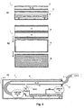
- Fig. 2 is an orthogonal diagram illustrating an air channel 10 according to principles of the present invention.
- Fig. 2a is a transverse view along the B-B cross-section (of Fig. 2b)
- Fig. 2b is a longitudinal view along the A-A cross-section (of Fig. 2a ) of the air channel 10.
- the air channel 10 includes an enclosure 14 within which two elongated openings, 16 and 18 are formed.
- One of the openings, e.g. 18, routes air from the ambient outside air to the pump 20 ( Fig. 1 ), and the other, e.g. 16, routes air from the pump 20 to the cuff 30.
- Fig. 2 is a flattened channel having one cross-sectional dimension, e.g. the horizontal dimension in Fig. 2a , substantially greater than the other cross-sectional dimension, e.g. the vertical dimension in Fig. 2a.
- Fig. 2c illustrates a side view
- Fig. 2d illustrates a top view of the air channel 10 with the openings 16 and 18 in the enclosure 14 illustrated by hidden (dashed) lines.
- Fig. 3 is an assembly diagram of a non-invasive blood pressure monitoring system 1 according to principles of the present invention.
- Fig. 3a is a side assembly view
- Fig. 3b is a top assembly view
- Fig. 3c is a more detailed side view of the system 1 as assembled.
- the air channel 10, containing the openings 16 and 18, is aligned over the housing 40.
- the electronic circuitry 50 is mounted within the housing 40.
- a gasket 70 is installed between the air channel 10 and the housing 40 and aligned with the top edges of the housing 40.
- the gasket 70 forms a water proof seal between the air channel 10 and the housing 40, giving the enclosure an IPX7 international protection rating.
- the air channel 10 may be cleaned by being flushed with air and/or liquid. In some embodiments, the air channel 10 may be removed from the housing 40 to access the electronic circuitry 50.
- One skilled in the art recognizes that there are alternate ways, other than using a gasket, of sealing the housing 40.
- Fig. 3c shows a more detailed side view of the non-invasive blood pressure monitoring system 1 as assembled.
- the electronic circuitry 50 provides control signals to the pump and valves 20 and receives sensor signals from the pressure sensors (PS) 62 and 64.
- the air channel 10 is connected to the pump and valves 20 via tubes or hoses 4 and 6, and to the cuff 30 via tube or hose 8. The place where the air channel 10 passes through the housing 40 is sealed with a gasket 70 to maintain the IPX7 rating.
- the pump and valves 20 are controlled by the electronic circuitry 50 by signals provided from the electronic circuitry 50 to the pump and valves 20. Similarly pressure representative signals are supplied to the electronic circuitry 50 from the pressure sensors (PS) 62, 64.
- a signal BP representing the blood pressure measurement produced by the electronic circuitry 50 is supplied to the display device 42 which displays the results of the blood pressure measurements.
- the display device is viewable from outside of the housing 40, and maintains a seal between the inside and outside of the housing 40 to an IPX7 rating level.
- the system 1 may record the blood pressure measurement data for later study, and/or transmit it to remote monitoring equipment, in addition to or in place of, displaying the blood pressure measurement.
- the signal BP is coupled to other circuitry (not shown) such as a recorder and/or transmitter.
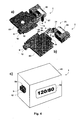
- Fig. 4 is a more detailed isometric diagram illustrating a non-invasive blood pressure monitoring system 1 according to principles of the present invention. Those elements which are the same as those illustrated in Fig. 1 and Fig. 3 are designated by the same reference number and are not described in detail below.
- Fig. 4a is an isometric view of the top of a portion of the system 1 in an assembled state
- Fig. 4b is an isometric view of the bottom of the portion of the system 1 in a partially disassembled state.
- the portion of the system 1 illustrated in Fig. 4a and Fig. 4b is the portion which resides inside the housing 40 during normal operation.
- the electronic circuitry 50 contains the electronic components (not shown) for performing the processing described above to provide blood pressure measurements.
- the air channel 10 is attached to the electronic circuitry 50 and includes inlet and exhaust port 12 and a port 9 attachable to the cuff 30.
- the inlet and exhaust port 12 includes four ports to the ambient air in the vicinity of the corners of the port 12. These ports are connected internally to opening 18 which connects those ports to an input port of the pump and valves 20 (in which the valves are illustrated as 21 and the pump is illustrated as 22) via tube or hose 6.
- the output port of the pump and valves 20 is connected to opening 16 via tube or hose 4.
- the opening 16 is connected to a port 9 located in the center of the inlet and exhaust port 12.
- a tube or hose 8 (not shown to simplify the figure) connected to a cuff 30 (also not shown) may be connected to the port 9.
- Pressure sensor 62 is coupled to opening 16 via a tube or hose 66 and pressure sensor 64 is coupled to opening 18 via a tube or hose 68.
- Fig. 4c illustrates the housing 40 into which the assembly illustrated in Fig. 4a and Fig. 4b is inserted.
- the inlet and exhaust ports 12 and the cuff port 9 have access to the outside of the housing 40.
- the inlet and exhaust ports 12 receive and exhaust air to the outside ambient atmosphere, and the cuff port 9 connects to the cuff 30 (not shown) via a tube or hose 8 (also not shown).
- a gasket 70 is interposed between the inlet and exhaust ports 12 and cuff port 9 and the housing 40 to provide the IPX7 seal.
- a display device 42 is illustrated displaying the result of a blood pressure measurement. As described above, however, the system 1 may record blood pressure measurements for later study, or transmit them to a remote location, either instead of or in addition to displaying them on a display device 42.
- the system 1 illustrated in Fig. 4 operates in the manner described above to generate a blood pressure measurement representative signal.
- the air channel 10 is flushed with air or a liquid such as water or a disinfectant.
- the air channel 10 may be also removed from the housing 40 and cleaned.
- the air channel 10 may be reassembled with the housing 40 using a gasket 70, the tubes or hoses 4, 6, 8, 66 and 68 reconnected, and operation of the system 1 resumed.
Landscapes
- Health & Medical Sciences (AREA)
- Life Sciences & Earth Sciences (AREA)
- Cardiology (AREA)
- Vascular Medicine (AREA)
- Biomedical Technology (AREA)
- Molecular Biology (AREA)
- Physiology (AREA)
- Biophysics (AREA)
- Pathology (AREA)
- Engineering & Computer Science (AREA)
- Veterinary Medicine (AREA)
- Heart & Thoracic Surgery (AREA)
- Medical Informatics (AREA)
- Physics & Mathematics (AREA)
- Surgery (AREA)
- Animal Behavior & Ethology (AREA)
- General Health & Medical Sciences (AREA)
- Public Health (AREA)
- Ophthalmology & Optometry (AREA)
- Measuring Pulse, Heart Rate, Blood Pressure Or Blood Flow (AREA)
- External Artificial Organs (AREA)
Claims (16)
- Système (1) de surveillance de la pression sanguine non invasive, comprenant :un conduit d'air (10) comportant un ou plusieurs orifices d'entrée et de sortie (12) communiquant avec l'air ambiant ;une pompe à commande électronique (20) pour gonfler un brassard (30) appliqué sur un membre d'un patient via ledit conduit d'air (10) ; etun boîtier hermétique étanche à l'eau (40) contenant la pompe à commande électronique (20) et un circuit électronique (50) situé à l'intérieur du boîtier (40) pour traiter des signaux servant à dériver une mesure de la pression sanguine en association avec le gonflage et le dégonflage dudit brassard(30),caractérisé en ce que ledit boîtier hermétique (40) est également étanche par rapport audit conduit d'air (10) pour empêcher que de l'air et/ou du liquide introduit ou expulsé via ledit conduit d'air (10) ne s'écoule à l'intérieur du boîtier (40) et ne vienne en contact avec ledit circuit électronique (50) ; dans lequel ledit conduit d'air (10) est isolé par rapport audit boîtier hermétique (40) et ledit conduit d'air forme un trajet exclusif pour le passage d'air depuis l'air ambiant jusque dans le brassard (30) sans fuite d'air ou de liquide dans le boîtier (40).
- Système selon la revendication 1, dans lequel ledit conduit d'air (10) peut être rincé par au moins (a) de l'air et/ou (b) du liquide.
- Système selon la revendication 1, dans lequel ledit système (1) permet audit boîtier d'avoir un indice de protection internationale IPX7.
- Système selon la revendication 1, dans lequel ledit conduit d'air (10) reçoit et expulse de façon exclusive de l'air via ledit conduit d'air (10) sensiblement sans fuite d'air dans ledit boîtier (40).
- Système selon la revendication 1, dans lequel ledit conduit d'air (10) est un conduit aplati ayant une dimension de section transversale sensiblement supérieure à l'autre dimension de section transversale.
- Système selon la revendication 1, dans lequel ledit boîtier hermétique étanche à l'eau (40) contient un circuit électronique (50) destiné à commander ladite pompe (20).
- Système selon la revendication 1, dans lequel ledit boîtier hermétique étanche à l'eau (40) est étanche par rapport audit conduit d'air (10) grâce à un joint d'étanchéité (70).
- Système selon la revendication 1, dans lequel ladite pompe à commande électronique (20) dégonfle ledit brassard (30) appliqué sur ledit membre du patient via ledit conduit d'air (10) qui comporte un ou plusieurs orifices d'entrée et de sortie (12) communiquant avec l'air ambiant.
- Système selon la revendication 8, dans lequel ledit conduit d'air (10) peut être rincé par au moins (a) de l'air et/ou (b) du liquide.
- Système selon la revendication 8, dans lequel ledit système (1) permet audit boîtier d'avoir un indice de protection internationale IPX7.
- Système selon la revendication 8, dans lequel ledit conduit d'air (10) reçoit et expulse de façon exclusive de l'air via ledit conduit d'air (10) sans fuite d'air dans ledit boîtier (40).
- Système selon la revendication 8, dans lequel ledit conduit d'air (10) est un conduit aplati ayant une dimension de section transversale sensiblement supérieure à l'autre dimension de section transversale.
- Système selon la revendication 8, dans lequel ledit boîtier hermétique étanche à l'eau (40) contient un circuit électronique (50) destiné à commander ladite pompe (20).
- Système selon la revendication 8, dans lequel ledit boîtier hermétique étanche à l'eau (40) est étanche par rapport audit conduit d'air (10) grâce à un joint d'étanchéité (70).
- Système selon la revendication 1, dans lequel ledit conduit d'air (10) peut être sélectivement retiré.
- Système selon la revendication 8, dans lequel ledit conduit d'air (10) peut être sélectivement retiré.
Applications Claiming Priority (2)
| Application Number | Priority Date | Filing Date | Title |
|---|---|---|---|
| US86518706P | 2006-11-10 | 2006-11-10 | |
| PCT/US2007/084264 WO2008061005A2 (fr) | 2006-11-10 | 2007-11-09 | Système de surveillance de la pression sanguine non invasive |
Publications (2)
| Publication Number | Publication Date |
|---|---|
| EP2086401A2 EP2086401A2 (fr) | 2009-08-12 |
| EP2086401B1 true EP2086401B1 (fr) | 2014-04-16 |
Family
ID=39276190
Family Applications (1)
| Application Number | Title | Priority Date | Filing Date |
|---|---|---|---|
| EP07845025.1A Active EP2086401B1 (fr) | 2006-11-10 | 2007-11-09 | Systeme de surveillance de la pression sanguine non invasive |
Country Status (4)
| Country | Link |
|---|---|
| US (1) | US8900155B2 (fr) |
| EP (1) | EP2086401B1 (fr) |
| CN (1) | CN101534705B (fr) |
| WO (1) | WO2008061005A2 (fr) |
Families Citing this family (8)
| Publication number | Priority date | Publication date | Assignee | Title |
|---|---|---|---|---|
| US8672853B2 (en) * | 2010-06-15 | 2014-03-18 | Bam Labs, Inc. | Pressure sensor for monitoring a subject and pressure sensor with inflatable bladder |
| CN101953681B (zh) * | 2010-10-21 | 2012-06-13 | 河南科技大学 | 可浸入式防水型电子血压计 |
| US10357421B2 (en) * | 2011-04-26 | 2019-07-23 | Vasper Systems, Llc | Apparatus and method for enhanced HGH generation in humans |
| JP6560920B2 (ja) * | 2015-07-14 | 2019-08-14 | 日本光電工業株式会社 | 血圧測定装置 |
| CN109700444A (zh) * | 2019-01-24 | 2019-05-03 | 深圳金亿帝医疗设备股份有限公司 | 血压测量设备以及集成气泵 |
| MX2021012686A (es) | 2019-04-17 | 2022-01-06 | Masimo Corp | Sistemas, dispositivos y metodos para monitoreo del paciente. |
| CN112075929B (zh) * | 2019-06-12 | 2024-11-12 | 深圳市理邦精密仪器股份有限公司 | 气路清洁的方法、装置及无创血压监护设备 |
| USD919100S1 (en) | 2019-08-16 | 2021-05-11 | Masimo Corporation | Holder for a patient monitor |
Family Cites Families (11)
| Publication number | Priority date | Publication date | Assignee | Title |
|---|---|---|---|---|
| US4178918A (en) | 1977-09-15 | 1979-12-18 | Cornwell Lionel B | Automatic blood pressure measuring and recording system |
| US4800892A (en) * | 1986-07-21 | 1989-01-31 | Nippon Colin Co., Ltd. | Apparatus for inflating cuff for blood pressure monitoring system |
| US4898180A (en) * | 1987-09-23 | 1990-02-06 | Farrelly Susan E | Personal blood pressure monitor |
| CN2040768U (zh) * | 1988-08-31 | 1989-07-12 | 金阳昇 | 一种带按压式压力控制阀的血压计 |
| EP0755653B1 (fr) | 1995-07-27 | 2001-04-11 | Agilent Technologies Deutschland GmbH | Module de surveillance de patient |
| DE69508942T2 (de) | 1995-10-19 | 1999-08-05 | Hewlett-Packard Gmbh, 71034 Boeblingen | Gehäuse für elektronische Bauteile |
| DE69513830T2 (de) * | 1995-10-19 | 2000-04-13 | Hewlett-Packard Gmbh | Blutdruck-Messgerät in Modulbauweise |
| US6175752B1 (en) * | 1998-04-30 | 2001-01-16 | Therasense, Inc. | Analyte monitoring device and methods of use |
| US6554798B1 (en) * | 1998-08-18 | 2003-04-29 | Medtronic Minimed, Inc. | External infusion device with remote programming, bolus estimator and/or vibration alarm capabilities |
| US6344025B1 (en) * | 1999-02-19 | 2002-02-05 | Omron Corporation | Blood pressure monitor |
| US20070282208A1 (en) * | 2006-06-06 | 2007-12-06 | Bob Jacobs | Mobile computing device with integrated medical devices |
-
2007
- 2007-11-09 EP EP07845025.1A patent/EP2086401B1/fr active Active
- 2007-11-09 US US12/446,270 patent/US8900155B2/en active Active
- 2007-11-09 WO PCT/US2007/084264 patent/WO2008061005A2/fr not_active Ceased
- 2007-11-09 CN CN200780041890.9A patent/CN101534705B/zh active Active
Also Published As
| Publication number | Publication date |
|---|---|
| US8900155B2 (en) | 2014-12-02 |
| WO2008061005A3 (fr) | 2008-07-10 |
| CN101534705B (zh) | 2012-06-20 |
| WO2008061005A2 (fr) | 2008-05-22 |
| CN101534705A (zh) | 2009-09-16 |
| EP2086401A2 (fr) | 2009-08-12 |
| US20100298723A1 (en) | 2010-11-25 |
Similar Documents
| Publication | Publication Date | Title |
|---|---|---|
| EP2086401B1 (fr) | Systeme de surveillance de la pression sanguine non invasive | |
| US6869403B2 (en) | Blood-pressure determining apparatus | |
| US6743179B2 (en) | Arteriostenosis inspecting apparatus | |
| US20020052554A1 (en) | Automatic blood-pressure measuring apparatus | |
| US20020138010A1 (en) | Continuous blood-pressure monitoring apparatus | |
| DE50014533D1 (de) | Kontinuierliches nicht-invasives Blutdruckmessgerät | |
| US6346083B1 (en) | Blood-pressure measuring device | |
| JP3417967B2 (ja) | 血圧監視装置と接続して用いられるマニホールド | |
| US6802814B2 (en) | Pressure-pulse-wave detecting apparatus | |
| KR100899385B1 (ko) | 전자식 혈압계 | |
| US5421341A (en) | Blood pressure measuring device | |
| US20030163053A1 (en) | Blood-pressure measuring apparatus and inferior-and-superior-limb blood-pressure-index measuring apparatus | |
| US6669646B1 (en) | Arteriosclerosis evaluating apparatus | |
| EP1808123B1 (fr) | Dispositif de mesure de la pression arterielle et procede de mesure de la pression arterielle | |
| US6394959B1 (en) | Continuous blood-pressure monitor apparatus | |
| US4996992A (en) | Automatic blood pressure measurement in hyperbaric chamber | |
| JPH03109037A (ja) | 一体状の音響ピックアップカップ付血圧用加圧帯 | |
| JPH027937A (ja) | 血圧測定用空気コネクタ | |
| JPWO2004069049A1 (ja) | 血圧脈波測定装置及び血圧脈波測定用装着具 | |
| CN219680612U (zh) | 医用全自动上臂式电子血压计 | |
| Sieber et al. | An underwater blood pressure measuring device | |
| JPH0523148B2 (fr) | ||
| JP3687546B2 (ja) | 血圧計 | |
| JPS5813843Y2 (ja) | 血圧測定用腕帯 | |
| WO1997012542A1 (fr) | Brassard pneumatique ameliore de controle de la tension arterielle |
Legal Events
| Date | Code | Title | Description |
|---|---|---|---|
| PUAI | Public reference made under article 153(3) epc to a published international application that has entered the european phase |
Free format text: ORIGINAL CODE: 0009012 |
|
| 17P | Request for examination filed |
Effective date: 20090508 |
|
| AK | Designated contracting states |
Kind code of ref document: A2 Designated state(s): AT BE BG CH CY CZ DE DK EE ES FI FR GB GR HU IE IS IT LI LT LU LV MC MT NL PL PT RO SE SI SK TR |
|
| DAX | Request for extension of the european patent (deleted) | ||
| 17Q | First examination report despatched |
Effective date: 20100120 |
|
| RIN1 | Information on inventor provided before grant (corrected) |
Inventor name: RISHER-KELLY, CLIFFORD MARK Inventor name: ZHEN, KEN |
|
| GRAP | Despatch of communication of intention to grant a patent |
Free format text: ORIGINAL CODE: EPIDOSNIGR1 |
|
| GRAJ | Information related to disapproval of communication of intention to grant by the applicant or resumption of examination proceedings by the epo deleted |
Free format text: ORIGINAL CODE: EPIDOSDIGR1 |
|
| GRAP | Despatch of communication of intention to grant a patent |
Free format text: ORIGINAL CODE: EPIDOSNIGR1 |
|
| INTG | Intention to grant announced |
Effective date: 20131029 |
|
| INTG | Intention to grant announced |
Effective date: 20131108 |
|
| GRAS | Grant fee paid |
Free format text: ORIGINAL CODE: EPIDOSNIGR3 |
|
| GRAA | (expected) grant |
Free format text: ORIGINAL CODE: 0009210 |
|
| AK | Designated contracting states |
Kind code of ref document: B1 Designated state(s): AT BE BG CH CY CZ DE DK EE ES FI FR GB GR HU IE IS IT LI LT LU LV MC MT NL PL PT RO SE SI SK TR |
|
| REG | Reference to a national code |
Ref country code: GB Ref legal event code: FG4D |
|
| REG | Reference to a national code |
Ref country code: CH Ref legal event code: EP |
|
| REG | Reference to a national code |
Ref country code: AT Ref legal event code: REF Ref document number: 662011 Country of ref document: AT Kind code of ref document: T Effective date: 20140515 |
|
| REG | Reference to a national code |
Ref country code: IE Ref legal event code: FG4D |
|
| REG | Reference to a national code |
Ref country code: DE Ref legal event code: R096 Ref document number: 602007036167 Country of ref document: DE Effective date: 20140528 |
|
| REG | Reference to a national code |
Ref country code: AT Ref legal event code: MK05 Ref document number: 662011 Country of ref document: AT Kind code of ref document: T Effective date: 20140416 |
|
| REG | Reference to a national code |
Ref country code: NL Ref legal event code: VDEP Effective date: 20140416 |
|
| REG | Reference to a national code |
Ref country code: LT Ref legal event code: MG4D |
|
| PG25 | Lapsed in a contracting state [announced via postgrant information from national office to epo] |
Ref country code: CY Free format text: LAPSE BECAUSE OF FAILURE TO SUBMIT A TRANSLATION OF THE DESCRIPTION OR TO PAY THE FEE WITHIN THE PRESCRIBED TIME-LIMIT Effective date: 20140416 Ref country code: LT Free format text: LAPSE BECAUSE OF FAILURE TO SUBMIT A TRANSLATION OF THE DESCRIPTION OR TO PAY THE FEE WITHIN THE PRESCRIBED TIME-LIMIT Effective date: 20140416 Ref country code: NL Free format text: LAPSE BECAUSE OF FAILURE TO SUBMIT A TRANSLATION OF THE DESCRIPTION OR TO PAY THE FEE WITHIN THE PRESCRIBED TIME-LIMIT Effective date: 20140416 Ref country code: BG Free format text: LAPSE BECAUSE OF FAILURE TO SUBMIT A TRANSLATION OF THE DESCRIPTION OR TO PAY THE FEE WITHIN THE PRESCRIBED TIME-LIMIT Effective date: 20140716 Ref country code: GR Free format text: LAPSE BECAUSE OF FAILURE TO SUBMIT A TRANSLATION OF THE DESCRIPTION OR TO PAY THE FEE WITHIN THE PRESCRIBED TIME-LIMIT Effective date: 20140717 Ref country code: IS Free format text: LAPSE BECAUSE OF FAILURE TO SUBMIT A TRANSLATION OF THE DESCRIPTION OR TO PAY THE FEE WITHIN THE PRESCRIBED TIME-LIMIT Effective date: 20140816 Ref country code: FI Free format text: LAPSE BECAUSE OF FAILURE TO SUBMIT A TRANSLATION OF THE DESCRIPTION OR TO PAY THE FEE WITHIN THE PRESCRIBED TIME-LIMIT Effective date: 20140416 |
|
| PG25 | Lapsed in a contracting state [announced via postgrant information from national office to epo] |
Ref country code: ES Free format text: LAPSE BECAUSE OF FAILURE TO SUBMIT A TRANSLATION OF THE DESCRIPTION OR TO PAY THE FEE WITHIN THE PRESCRIBED TIME-LIMIT Effective date: 20140416 Ref country code: PL Free format text: LAPSE BECAUSE OF FAILURE TO SUBMIT A TRANSLATION OF THE DESCRIPTION OR TO PAY THE FEE WITHIN THE PRESCRIBED TIME-LIMIT Effective date: 20140416 Ref country code: LV Free format text: LAPSE BECAUSE OF FAILURE TO SUBMIT A TRANSLATION OF THE DESCRIPTION OR TO PAY THE FEE WITHIN THE PRESCRIBED TIME-LIMIT Effective date: 20140416 Ref country code: AT Free format text: LAPSE BECAUSE OF FAILURE TO SUBMIT A TRANSLATION OF THE DESCRIPTION OR TO PAY THE FEE WITHIN THE PRESCRIBED TIME-LIMIT Effective date: 20140416 Ref country code: SE Free format text: LAPSE BECAUSE OF FAILURE TO SUBMIT A TRANSLATION OF THE DESCRIPTION OR TO PAY THE FEE WITHIN THE PRESCRIBED TIME-LIMIT Effective date: 20140416 |
|
| PG25 | Lapsed in a contracting state [announced via postgrant information from national office to epo] |
Ref country code: PT Free format text: LAPSE BECAUSE OF FAILURE TO SUBMIT A TRANSLATION OF THE DESCRIPTION OR TO PAY THE FEE WITHIN THE PRESCRIBED TIME-LIMIT Effective date: 20140818 |
|
| REG | Reference to a national code |
Ref country code: DE Ref legal event code: R097 Ref document number: 602007036167 Country of ref document: DE |
|
| PG25 | Lapsed in a contracting state [announced via postgrant information from national office to epo] |
Ref country code: RO Free format text: LAPSE BECAUSE OF FAILURE TO SUBMIT A TRANSLATION OF THE DESCRIPTION OR TO PAY THE FEE WITHIN THE PRESCRIBED TIME-LIMIT Effective date: 20140416 Ref country code: EE Free format text: LAPSE BECAUSE OF FAILURE TO SUBMIT A TRANSLATION OF THE DESCRIPTION OR TO PAY THE FEE WITHIN THE PRESCRIBED TIME-LIMIT Effective date: 20140416 Ref country code: DK Free format text: LAPSE BECAUSE OF FAILURE TO SUBMIT A TRANSLATION OF THE DESCRIPTION OR TO PAY THE FEE WITHIN THE PRESCRIBED TIME-LIMIT Effective date: 20140416 Ref country code: BE Free format text: LAPSE BECAUSE OF FAILURE TO SUBMIT A TRANSLATION OF THE DESCRIPTION OR TO PAY THE FEE WITHIN THE PRESCRIBED TIME-LIMIT Effective date: 20140416 Ref country code: CZ Free format text: LAPSE BECAUSE OF FAILURE TO SUBMIT A TRANSLATION OF THE DESCRIPTION OR TO PAY THE FEE WITHIN THE PRESCRIBED TIME-LIMIT Effective date: 20140416 Ref country code: SK Free format text: LAPSE BECAUSE OF FAILURE TO SUBMIT A TRANSLATION OF THE DESCRIPTION OR TO PAY THE FEE WITHIN THE PRESCRIBED TIME-LIMIT Effective date: 20140416 |
|
| PLBE | No opposition filed within time limit |
Free format text: ORIGINAL CODE: 0009261 |
|
| STAA | Information on the status of an ep patent application or granted ep patent |
Free format text: STATUS: NO OPPOSITION FILED WITHIN TIME LIMIT |
|
| 26N | No opposition filed |
Effective date: 20150119 |
|
| PG25 | Lapsed in a contracting state [announced via postgrant information from national office to epo] |
Ref country code: IT Free format text: LAPSE BECAUSE OF FAILURE TO SUBMIT A TRANSLATION OF THE DESCRIPTION OR TO PAY THE FEE WITHIN THE PRESCRIBED TIME-LIMIT Effective date: 20140416 |
|
| REG | Reference to a national code |
Ref country code: DE Ref legal event code: R097 Ref document number: 602007036167 Country of ref document: DE Effective date: 20150119 |
|
| PG25 | Lapsed in a contracting state [announced via postgrant information from national office to epo] |
Ref country code: LU Free format text: LAPSE BECAUSE OF FAILURE TO SUBMIT A TRANSLATION OF THE DESCRIPTION OR TO PAY THE FEE WITHIN THE PRESCRIBED TIME-LIMIT Effective date: 20141109 Ref country code: MC Free format text: LAPSE BECAUSE OF FAILURE TO SUBMIT A TRANSLATION OF THE DESCRIPTION OR TO PAY THE FEE WITHIN THE PRESCRIBED TIME-LIMIT Effective date: 20140416 |
|
| REG | Reference to a national code |
Ref country code: CH Ref legal event code: PL |
|
| REG | Reference to a national code |
Ref country code: DE Ref legal event code: R082 Ref document number: 602007036167 Country of ref document: DE Representative=s name: HASELTINE LAKE LLP, DE |
|
| PG25 | Lapsed in a contracting state [announced via postgrant information from national office to epo] |
Ref country code: LI Free format text: LAPSE BECAUSE OF NON-PAYMENT OF DUE FEES Effective date: 20141130 Ref country code: CH Free format text: LAPSE BECAUSE OF NON-PAYMENT OF DUE FEES Effective date: 20141130 Ref country code: SI Free format text: LAPSE BECAUSE OF FAILURE TO SUBMIT A TRANSLATION OF THE DESCRIPTION OR TO PAY THE FEE WITHIN THE PRESCRIBED TIME-LIMIT Effective date: 20140416 |
|
| REG | Reference to a national code |
Ref country code: IE Ref legal event code: MM4A |
|
| PG25 | Lapsed in a contracting state [announced via postgrant information from national office to epo] |
Ref country code: IE Free format text: LAPSE BECAUSE OF NON-PAYMENT OF DUE FEES Effective date: 20141109 |
|
| REG | Reference to a national code |
Ref country code: FR Ref legal event code: PLFP Year of fee payment: 9 |
|
| PG25 | Lapsed in a contracting state [announced via postgrant information from national office to epo] |
Ref country code: MT Free format text: LAPSE BECAUSE OF FAILURE TO SUBMIT A TRANSLATION OF THE DESCRIPTION OR TO PAY THE FEE WITHIN THE PRESCRIBED TIME-LIMIT Effective date: 20140416 Ref country code: HU Free format text: LAPSE BECAUSE OF FAILURE TO SUBMIT A TRANSLATION OF THE DESCRIPTION OR TO PAY THE FEE WITHIN THE PRESCRIBED TIME-LIMIT; INVALID AB INITIO Effective date: 20071109 Ref country code: TR Free format text: LAPSE BECAUSE OF FAILURE TO SUBMIT A TRANSLATION OF THE DESCRIPTION OR TO PAY THE FEE WITHIN THE PRESCRIBED TIME-LIMIT Effective date: 20140416 |
|
| REG | Reference to a national code |
Ref country code: FR Ref legal event code: PLFP Year of fee payment: 10 |
|
| REG | Reference to a national code |
Ref country code: FR Ref legal event code: PLFP Year of fee payment: 11 |
|
| REG | Reference to a national code |
Ref country code: DE Ref legal event code: R082 Ref document number: 602007036167 Country of ref document: DE Representative=s name: HL KEMPNER PATENTANWALT, RECHTSANWALT, SOLICIT, DE Country of ref document: DE Representative=s name: HL KEMPNER PATENTANWAELTE, SOLICITORS (ENGLAND, DE Ref country code: DE Ref legal event code: R082 Ref document number: 602007036167 Ref country code: DE Ref legal event code: R082 Ref document number: 602007036167 Country of ref document: DE Representative=s name: HL KEMPNER PARTG MBB, DE |
|
| REG | Reference to a national code |
Ref country code: GB Ref legal event code: 732E Free format text: REGISTERED BETWEEN 20240523 AND 20240529 |
|
| REG | Reference to a national code |
Ref country code: DE Ref legal event code: R082 Ref document number: 602007036167 Country of ref document: DE Representative=s name: HL KEMPNER PATENTANWAELTE, SOLICITORS (ENGLAND, DE Ref country code: DE Ref legal event code: R082 Ref document number: 602007036167 Country of ref document: DE Ref country code: DE Ref legal event code: R081 Ref document number: 602007036167 Country of ref document: DE Owner name: DRAEGERWERK AG & CO. KGAA, DE Free format text: FORMER OWNER: DRAEGER MEDICAL SYSTEMS, INC., ANDOVER, MASS., US Ref country code: DE Ref legal event code: R082 Ref document number: 602007036167 Country of ref document: DE Representative=s name: HL KEMPNER PARTG MBB, DE |
|
| REG | Reference to a national code |
Ref country code: DE Ref legal event code: R082 Ref document number: 602007036167 Country of ref document: DE Representative=s name: HL KEMPNER PATENTANWAELTE, SOLICITORS (ENGLAND, DE Ref country code: DE Ref legal event code: R082 Ref document number: 602007036167 Country of ref document: DE Representative=s name: HL KEMPNER PARTG MBB, DE |
|
| PGFP | Annual fee paid to national office [announced via postgrant information from national office to epo] |
Ref country code: GB Payment date: 20260309 Year of fee payment: 19 |
|
| PGFP | Annual fee paid to national office [announced via postgrant information from national office to epo] |
Ref country code: DE Payment date: 20260320 Year of fee payment: 19 |
|
| PGFP | Annual fee paid to national office [announced via postgrant information from national office to epo] |
Ref country code: FR Payment date: 20260313 Year of fee payment: 19 |