EP2086704B1 - Verfahren zur herstellung von feingussteilen durch schleuderguss - Google Patents
Verfahren zur herstellung von feingussteilen durch schleuderguss Download PDFInfo
- Publication number
- EP2086704B1 EP2086704B1 EP06806464A EP06806464A EP2086704B1 EP 2086704 B1 EP2086704 B1 EP 2086704B1 EP 06806464 A EP06806464 A EP 06806464A EP 06806464 A EP06806464 A EP 06806464A EP 2086704 B1 EP2086704 B1 EP 2086704B1
- Authority
- EP
- European Patent Office
- Prior art keywords
- melt
- rotor
- mold
- crucible
- pressure
- Prior art date
- Legal status (The legal status is an assumption and is not a legal conclusion. Google has not performed a legal analysis and makes no representation as to the accuracy of the status listed.)
- Not-in-force
Links
- 238000009750 centrifugal casting Methods 0.000 title claims abstract description 15
- 238000004519 manufacturing process Methods 0.000 title claims description 13
- 238000005495 investment casting Methods 0.000 title claims description 8
- 239000000155 melt Substances 0.000 claims abstract description 64
- 229910052751 metal Inorganic materials 0.000 claims abstract description 16
- 239000002184 metal Substances 0.000 claims abstract description 16
- 238000000034 method Methods 0.000 claims description 33
- 239000010936 titanium Substances 0.000 claims description 15
- 229910001069 Ti alloy Inorganic materials 0.000 claims description 11
- 229910052719 titanium Inorganic materials 0.000 claims description 8
- 229910052758 niobium Inorganic materials 0.000 claims description 7
- 229910045601 alloy Inorganic materials 0.000 claims description 6
- 239000000956 alloy Substances 0.000 claims description 6
- 239000000470 constituent Substances 0.000 claims description 6
- 229910052804 chromium Inorganic materials 0.000 claims description 5
- 229910052748 manganese Inorganic materials 0.000 claims description 5
- 239000000203 mixture Substances 0.000 claims description 4
- 229910006281 γ-TiAl Inorganic materials 0.000 claims description 4
- 229910052750 molybdenum Inorganic materials 0.000 claims description 3
- 229910052715 tantalum Inorganic materials 0.000 claims description 3
- 229910052721 tungsten Inorganic materials 0.000 claims description 3
- 229910052720 vanadium Inorganic materials 0.000 claims description 3
- 238000005266 casting Methods 0.000 description 20
- 230000015572 biosynthetic process Effects 0.000 description 9
- 239000007789 gas Substances 0.000 description 8
- 239000000463 material Substances 0.000 description 8
- 239000011148 porous material Substances 0.000 description 7
- 230000007704 transition Effects 0.000 description 7
- 229910021324 titanium aluminide Inorganic materials 0.000 description 6
- RTAQQCXQSZGOHL-UHFFFAOYSA-N Titanium Chemical compound [Ti] RTAQQCXQSZGOHL-UHFFFAOYSA-N 0.000 description 5
- PNEYBMLMFCGWSK-UHFFFAOYSA-N aluminium oxide Inorganic materials [O-2].[O-2].[O-2].[Al+3].[Al+3] PNEYBMLMFCGWSK-UHFFFAOYSA-N 0.000 description 5
- 238000010438 heat treatment Methods 0.000 description 5
- 238000002844 melting Methods 0.000 description 5
- 230000008018 melting Effects 0.000 description 5
- OKTJSMMVPCPJKN-UHFFFAOYSA-N Carbon Chemical compound [C] OKTJSMMVPCPJKN-UHFFFAOYSA-N 0.000 description 4
- CPLXHLVBOLITMK-UHFFFAOYSA-N Magnesium oxide Chemical compound [Mg]=O CPLXHLVBOLITMK-UHFFFAOYSA-N 0.000 description 4
- 229910002804 graphite Inorganic materials 0.000 description 4
- 239000010439 graphite Substances 0.000 description 4
- 239000012535 impurity Substances 0.000 description 4
- RUDFQVOCFDJEEF-UHFFFAOYSA-N yttrium(III) oxide Inorganic materials [O-2].[O-2].[O-2].[Y+3].[Y+3] RUDFQVOCFDJEEF-UHFFFAOYSA-N 0.000 description 4
- PXHVJJICTQNCMI-UHFFFAOYSA-N Nickel Chemical compound [Ni] PXHVJJICTQNCMI-UHFFFAOYSA-N 0.000 description 3
- VYPSYNLAJGMNEJ-UHFFFAOYSA-N Silicium dioxide Chemical compound O=[Si]=O VYPSYNLAJGMNEJ-UHFFFAOYSA-N 0.000 description 3
- 238000005056 compaction Methods 0.000 description 3
- 229910000951 Aluminide Inorganic materials 0.000 description 2
- XKRFYHLGVUSROY-UHFFFAOYSA-N Argon Chemical compound [Ar] XKRFYHLGVUSROY-UHFFFAOYSA-N 0.000 description 2
- OQPDWFJSZHWILH-UHFFFAOYSA-N [Al].[Al].[Al].[Ti] Chemical compound [Al].[Al].[Al].[Ti] OQPDWFJSZHWILH-UHFFFAOYSA-N 0.000 description 2
- 239000000919 ceramic Substances 0.000 description 2
- 238000006243 chemical reaction Methods 0.000 description 2
- 239000003779 heat-resistant material Substances 0.000 description 2
- 230000001939 inductive effect Effects 0.000 description 2
- 238000002955 isolation Methods 0.000 description 2
- 239000000395 magnesium oxide Substances 0.000 description 2
- 238000007711 solidification Methods 0.000 description 2
- 230000008023 solidification Effects 0.000 description 2
- 229910010038 TiAl Inorganic materials 0.000 description 1
- 230000001133 acceleration Effects 0.000 description 1
- 229910052786 argon Inorganic materials 0.000 description 1
- 238000007796 conventional method Methods 0.000 description 1
- 238000001816 cooling Methods 0.000 description 1
- 230000007797 corrosion Effects 0.000 description 1
- 238000005260 corrosion Methods 0.000 description 1
- 239000011261 inert gas Substances 0.000 description 1
- 229910001092 metal group alloy Inorganic materials 0.000 description 1
- 229910052759 nickel Inorganic materials 0.000 description 1
- 230000003647 oxidation Effects 0.000 description 1
- 238000007254 oxidation reaction Methods 0.000 description 1
- 238000010791 quenching Methods 0.000 description 1
- 230000000171 quenching effect Effects 0.000 description 1
- 238000012958 reprocessing Methods 0.000 description 1
- 238000007789 sealing Methods 0.000 description 1
- 229910000601 superalloy Inorganic materials 0.000 description 1
- 238000013518 transcription Methods 0.000 description 1
- 230000035897 transcription Effects 0.000 description 1
Images

Classifications
-
- B—PERFORMING OPERATIONS; TRANSPORTING
- B22—CASTING; POWDER METALLURGY
- B22D—CASTING OF METALS; CASTING OF OTHER SUBSTANCES BY THE SAME PROCESSES OR DEVICES
- B22D13/00—Centrifugal casting; Casting by using centrifugal force
- B22D13/06—Centrifugal casting; Casting by using centrifugal force of solid or hollow bodies in moulds rotating around an axis arranged outside the mould
- B22D13/066—Centrifugal casting; Casting by using centrifugal force of solid or hollow bodies in moulds rotating around an axis arranged outside the mould several moulds being disposed in a circle
-
- B—PERFORMING OPERATIONS; TRANSPORTING
- B22—CASTING; POWDER METALLURGY
- B22D—CASTING OF METALS; CASTING OF OTHER SUBSTANCES BY THE SAME PROCESSES OR DEVICES
- B22D21/00—Casting non-ferrous metals or metallic compounds so far as their metallurgical properties are of importance for the casting procedure; Selection of compositions therefor
- B22D21/002—Castings of light metals
- B22D21/005—Castings of light metals with high melting point, e.g. Be 1280 degrees C, Ti 1725 degrees C
-
- F—MECHANICAL ENGINEERING; LIGHTING; HEATING; WEAPONS; BLASTING
- F05—INDEXING SCHEMES RELATING TO ENGINES OR PUMPS IN VARIOUS SUBCLASSES OF CLASSES F01-F04
- F05B—INDEXING SCHEME RELATING TO WIND, SPRING, WEIGHT, INERTIA OR LIKE MOTORS, TO MACHINES OR ENGINES FOR LIQUIDS COVERED BY SUBCLASSES F03B, F03D AND F03G
- F05B2230/00—Manufacture
- F05B2230/20—Manufacture essentially without removing material
- F05B2230/21—Manufacture essentially without removing material by casting
-
- F—MECHANICAL ENGINEERING; LIGHTING; HEATING; WEAPONS; BLASTING
- F05—INDEXING SCHEMES RELATING TO ENGINES OR PUMPS IN VARIOUS SUBCLASSES OF CLASSES F01-F04
- F05C—INDEXING SCHEME RELATING TO MATERIALS, MATERIAL PROPERTIES OR MATERIAL CHARACTERISTICS FOR MACHINES, ENGINES OR PUMPS OTHER THAN NON-POSITIVE-DISPLACEMENT MACHINES OR ENGINES
- F05C2201/00—Metals
- F05C2201/02—Light metals
- F05C2201/021—Aluminium
-
- F—MECHANICAL ENGINEERING; LIGHTING; HEATING; WEAPONS; BLASTING
- F05—INDEXING SCHEMES RELATING TO ENGINES OR PUMPS IN VARIOUS SUBCLASSES OF CLASSES F01-F04
- F05C—INDEXING SCHEME RELATING TO MATERIALS, MATERIAL PROPERTIES OR MATERIAL CHARACTERISTICS FOR MACHINES, ENGINES OR PUMPS OTHER THAN NON-POSITIVE-DISPLACEMENT MACHINES OR ENGINES
- F05C2201/00—Metals
- F05C2201/04—Heavy metals
- F05C2201/0403—Refractory metals, e.g. V, W
- F05C2201/0412—Titanium
Definitions
- the invention pertains to a method for production of precision castings by centrifugal casting.
- the method in particular pertains to the production of precision castings made of titanium or alloys containing large amounts of titanium, e. g. titanium aluminides.
- titanium aluminides are considered an optimum material in various areas of application because of their low density, relatively high-temperature, specific strength relative to nickel superalloys, and corrosion resistance.
- materials with a narrow range between solidus and liquidus temperatures like TiAl or pure titanium grade 2, are very difficult to shape, the only practical method for forming them is to cast them.
- US 5,950,706 discloses a method for production of castings by centrifugal casting.
- a centrifugal casting device having a rotor being rotatable around an axis.
- the rotor has at least one mold being accommodated in a first radial distance from the axis.
- a melt which is poured into a crucible being accommodated in the centre of the rotor.
- the rotor is rotated and thereby the melt is forced by means of centrifugal forces into the mold. This step is carried out under vacuum. As soon as the mold is completely filled with the melt gas pressure is increased up to atmospheric pressure.
- crucible In the sense of the present invention under a "crucible” there is in general understood a container which has sufficient heat resistance to take up a metallic melt without being damaged and without undergoing reactions with the metal melt.
- a “crucible” in the sense of the present invention may have any suitable shape. In particular it may have a cylindrical shape the bottom of which has a rounded concave shape. However, a “crucible” in the sense of the present invention may also be formed as a ring-like channel. Suitable materials for the production of a crucible are alumina, Y 2 O 3 , magnesia, silica glass, graphite and the like.
- the proposed method differs from conventional method in particular in that there is exerted a pressure on the melt after the mold has completely been filled. - The pressure is exerted on the melt until a predetermined cooling-temperature in a range of 1300°C to 800°C has been reached.
- the predetermined cooling-temperature depends on the used metal alloy.
- the predetermined cooling-temperature is advantageously selected to be lower than a brittle-ductile transition temperature of the used alloy.
- brittle-ductile transition temperature there is understood a temperature at which the bonds of an intermetallic phase change from metal bonds to atomic bonds. At temperatures above the brittle-ductile transition temperature intermetallic phases are bond by metal bonds. At such temperatures intermetallic phases are ductile. At a temperature below the brittle-ductile transition temperature intermetallic phases change their properties and become brittle.
- the predetermined cooling-temperature can be choosen to be for example 20°C to 200°C lower than the brittle-ductile transition temperature.
- the amount of the pressure which is exerted on the melt after the mold is completely filled corresponds to the centrifugal force acting on the melt at the moment when the mold is completely filled times a factor of 1.0 to 5.0.
- the centrifugal force depends on the rotational speed of the rotor, the first radius at which the mold is distanced from the axis and the mass of the melt. Under the term "first radius” there is understood the distance between the axis and an inlet opening of the mold.
- the pressure to be exerted on the melt is the centrifugal force at the precise moment of completely filling of the mold times a factor which is selected from a range of 1.0 to 5.0.
- the pressure being exerted upon the melt after the mold is completely filled may be higher than during the time when the mold is being filled.
- the pressure may be increased after the mold has been filled, preferably at a constant rate, for a predetermined period and afterwards there may be exerted a constant pressure on the melt.
- the predetermined period may be in the range of 1 to 25 seconds, preferably 5 to 20 seconds.
- the period of the constant pressure may be in range of 1 to 6 minutes, preferably of 4 to 6 minutes.
- the crucible is accommodated in the rotor at a second radial distance from the axis, the second radial distance being smaller than the first radial distance.
- the second radial distance may be calculated from an outlet opening of the crucible to the axis.
- the second radial distance is larger than a diameter of the crucible.
- the melt can be created in the crucible while the rotor is standing, i. e. while the rotor is not rotating.
- the melt can be created by inductively heating an ingot within the crucible. It is also possible to heat the ingot or to support the heating of the ingot by microwaves. By the proposed heating methods an ingot can be melt within several minutes.
- the mold is preheated before step lit. c.
- the temperature of said preheating may be in the range of 50°C to 1100°C, preferably in the range of 850°C to 1100°C.
- a preheating temperature is in particular useful when producing turbine blades.
- a temperature for said preheating in the range of 50°C to 250°C.
- the preheating temperature of the mold depends from the geometry of the casting and has to be determined for each geometry.
- the preheating of the mold can take place for example in a furnace from which the mold is transferred into the rotor before a centrifugal casting takes place.
- suitable heating device being provided at the centrifugal casting device, in particular at the rotor.
- the predetermined cooling-temperature is in a range of 1050°C to 800°C.
- Predetermined cooling-temperatures selected from this range are usually lower than the brittle-ductile transition temperature of titanium aluminides.
- the pressure can be exerted upon the melt in different manners.
- the pressure is exerted upon the melt by rotating the rotor.
- the pressure is created by centrifugal forces acting upon the melt.
- it is also possible to exert the pressure upon melt for example by pressurised gas.
- gas there may be used preferably an inert gas like Argon or the like.
- the melt is under vacuum or shield gas.
- vacuum is advantageous as therewith a formation of gas-filled pores and an oxidation of the metal, in particular of titan aluminides, can be avoided. It has been proven appropriate to use a vacuum of 10 -1 to 10 -2 bar in order to avoid the formation of in particular gas-filled pores.
- the solidifying melt is cooled down after step lit. e to room temperature at a cooling-rate of 50°C, to 150°C per hour.
- a cooling-rate can be realised by the use of molds having suitable thermal isolation properties. Molds without suitable thermal isolation properties may be placed in a furnace which is preheated upon a temperature which is in the range of the predetermined cooling-temperature. After transferring the mold into the furnace it may be cooled down by controlling the heating elements of the furnace so that the aforementioned cooling-rate is realised within the furnace. The proposed controlled cooling down of the mold also counteracts the formation of hot tears in the casting.
- the proposed method is in particular well suited for producing castings from a metal melt consisting of a titanium alloy.
- the titanium alloy advantageously comprises Ti and Al as main constituents.
- a suitable composition (in at.%) of a ⁇ -TiAl based alloy may be summarised as follows: Ti 45 - 52 at . % ⁇ Al 45 - 48 at . % ⁇ X ⁇ 1 1 - 3 at . % ⁇ X ⁇ 2 2 - 4 at . % ⁇ X ⁇ 3 1 at . % , where
- the titanium alloy may contain 30 to 45 wt.% Al, 1,5 to 6 wt.% Nb and as balance Ti as well as unavoidable impurities.
- the titanium alloy may further contain one or more of the further constituents: 0,5 to 3,0 wt.% Mn, 0,1 to 0,5 wt.% B, 1,5 to 3,5 wt.% Cr.
- the titanium alloy may contain O in an amount of 0 to 1000 ppm, C in an amount of 0 to 1000 ppm, preferably 800 to 1200 ppm, Ni in an amount of 100 to 1000 ppm and N in an amount of 0 to 1000 ppm.
- the melt is heated up during step lit. b to a temperature which is 50°C to 150°C higher than the melting temperature of the metal.
- a temperature which is 50°C to 150°C higher than the melting temperature of the metal By this measure the heat energy of the melt is increased.
- the metal melt being a titanium alloy containing Ti and Al as main constituents is poured into the crucible. This allows a production of larger quantities of metal melt. If in the rotor there is accommodated a multitude of molds, a multitude of castings can be produced simultaneously.
- the melt may be poured into the crucible while the rotor is rotating.
- the melt being poured into the crucible can be accelerated rapidly and can be forced with a high speed into the mold. Consequently, the mold is filled with the melt being at a relatively high temperature which in turn guaranties a certain mobility of the melt and therefore the pressure being exerted upon the melt during step lit. d can effectively be used to cold runs and to reduce pores.
- the crucible has the form of a ring-shaped channel being centrally accommodated in the rotor, the outer circumference of which having a second radial distance from the axis, the second distance being smaller than the first radial distance.
- the melt is poured into a ring-shaped channel at a radial distance with respect to the axis. Consequently, the centrifugal force acting upon the melt and therefore the velocity by which the melt is transferred into the mold can be increased by this measure.
- each arm 2 there is provided a first crucible 6 made of a heat resistant material, e. g. silica glass or the like.
- the first crucible 6 is mounted at a bottom of the arm 2, preferably in a gas-tight manner.
- the first crucible 6 is surrounded by an induction-coil 7 which can be moved in an essentially vertical direction. In an lower position (not shown here) of the induction-coil 7 it does not surround the first crucible 6 so that the first crucible 6 can be rotated with the rotor 1 around the axis A. Within the first crucible 6 there is accommodated a second crucible 8 having a outlet opening 9 which is placed opposite to the inlet opening 5 of the mold 4.
- the second crucible 8 is made of a heat-resistant material, e.g. alumina, Y 2 O 3 , graphite or the like. According to a preferred embodiment of the invention the second crucible 8 is made of alumina, magnesia or the like. There may be provided a third crucible (not shown here) made of graphite which may be placed within the second crucible 8. By the use of the third crucible an inductive melting of an ingot taken up therein can be accelerated.
- a window 10 Opposite to a bottom of the second crucible 8 there is provided a window 10 through which by means of a camera 11 the melting of the ingot may be observed.
- a hollow shaft 12 extending vertically from the rotor 1 may be driven by an electric motor (not shown here).
- a vacuum source e.g. a vacuum pump or the like, which is connected by means of a conventional sealing with the hollow shaft 12 to create within the rotor 1, which is designed in this case in a gas-tight manner, a vacuum.
- the rotor 1 may have breakthroughs 13.
- the rotor 1 may be surrounded by a gas-tight housing 14.
- the vacuum source may be connected to the gas-tight housing 14 to create therein and thereby also within the rotor 1 a vacuum.
- a source of a shield gas e.g. Ar or the like, by which the hollow structure surrounded by the rotor 1 may be flooded during the centrifugal casting process.
- a source of a shield gas e.g. Ar or the like
- the mold is accommodated within the rotor 1 at a first radial distance r1 and the second crucible 8 taking up a melt 15 is accommodated within the arm 2 at a second radial distance r2.
- the first radial distance is larger than the second radial distance.
- the second crucible has a cylindrical shape and the second radius is larger than the diameter of the crucible, i. e. the second crucible 8 is located eccentrically with respect to the axis A within the rotor 1.
- the rotor 1 may comprise more than two arms 2, e. g. 4, 6, 8 or more arms.
- the rotor 1 may also be disk-shaped.
- a first and a second crucible which are formed like ring-channels.
- These ring like channels again may be made for example of a heat-resistant ceramic like silica-glass, alumina, graphite and the like.
- One or more ingots taken up in the second crucible, which is formed as a ring-channel may be again heated by an induction-coil, which surrounds an inner and an outer diameter of the first crucible, which is as well formed like a ring-channel and which accommodates the second ring-channel like crucible.
- the second ring-channel like crucible may have several outlet openings. Vis-à-vis each outlet opening there is accommodated in a radial direction a corresponding mold with their inlet opening.
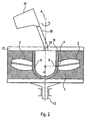
- Fig. 2 shows a second device in the rotor 1 of which there is centrically accommodated a fourth crucible 16, which may be made of alumina, Y 2 O 3 or the like. Vis-à-vis second openings 9 of the fourth crucible 16 there are provided molds 2 with their inlet openings 5 being located vis-à-vis the outlet openings 9. The inlet openings 5 are arranged again in a first radial distance r1 from the axis A.
- the fourth crucible 16 is arranged centrically with resepct to the axis A.
- a lid 17 having a centrically arranged opening 18 covers the fourth crucible 16.
- a fifth crucible 19 may be connected via a tube 20 with the opening 18 so that a melt can be poured from the fifth crucible 19 through the opening 18 into the fourth crucible 16.
- a mold which may be made of a ceramic being lined at their interior contact surface with Y 2 O 3 is preheated in a furnace up to a temperatures of around 1000°C. Suitable materials for the production of a mold are for example disclosed in the WO 2005/039803 A2 .
- the mold 4 being preheated to a temperature of around 1000°C is mounted at the arm 2 and then covered with the piston 3 which is mounted in a gas-tight manner at the arm 2.
- a multitude of molds 4 can be mounted at the rotor 1.
- the ingot is then melt by inducing currents with the induction-coil 7.
- the rotor 1 is accelerated within 0.5 to 2.0 seconds, preferably within less than 1.5 seconds, upon rotational speed of 110 to 260 rpm, preferably with 100 to 160 rpm.
- the second radius r2 is in this case chosen to be 300 to 400 mm, preferably around 350 mm.
- the melt is forced by centrifugal forces from the second crucible 8 into the mold 4.
- the rotor 1 is furtheron rotated at a rotational speed of 110 to 260 rpm, preferably of at least 160 rpm, for at least 60 seconds, preferably for 120 to 300 seconds.
- the rotational speed may be increased at a constant rate, e.g. from initial rotational speed selected from a range of 110 to 160 rpm to a rotational speed selected from a range of 180 to 260 rpm when the solidifying melt in the mold 4 has reached predetermined cooling-temperature in the range of 1300°C to 1100°C.
- the temperature of the solidifying melt in the mold 4 may be determined by conventional temperature measuring techniques using for example a thermocouple.
- the temperature values measured therewith may be corrected in accordance with a suitable algorithm in a conventional manner.
- the mold 4 is demounted from the arm 2 and then placed in the furnace which is preheated on a temperature of around 1000°C. The mold 4 is then cooled down within the furnace with a rate of 50°C to 100°C per hour.
- the rotor 1 may be evacuated before melting the ingot within the second crucible 8.
- the vacuum within the rotor 1 may be in the range of 10 -1 to 10 -2 bar.
- the rotor 1 may be flooded with shield gas, for example Ar before melting the ingot.
- Molds 4 are preheated in a similar manner as described above in a furnace up to a temperature of 1000°C and then placed in suitable holding devices provided within the rotor 1.
- the rotor 1 is accelerated upon a rotational speed in the range of 110 to 260 rpm. As soon as the melt has reached a predetermined temperature in the range of 1450°C to 1650°C the melt taken up in the fifth crucible 19 is poured into the fourth crucible 16. The melt is than forced through the outlet openings 9 provided at the fourth crucible 16 in the molds 4 which are located vis-à-vis.
- the rotor 1 is furtheron rotated as described above. After stopping the rotation the molds 4 are demounted from the rotor 1 and cooled down as described above.
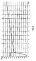
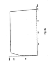
- Figs. 3a and 3b show plots of the rotational speed of the rotor above the time.
- Fig. 3a the acceleration of the rotor during the first 12 seconds from the beginning of the rotation is showed.
- Fig. 3b shows a rotational speed of the rotor from the beginning of the rotation until the rotation is stopped.
- this rotational speed may be in the range of 220 to 240 rpm, in particular around 225 rpm.
- the melt is poured from the fifth crucible 19 into the fourth crucible 16 for example around 0.5 to 1.0 seconds after the rotation of the rotor 1 has been started, e. g. at a moment when the rotor rotates with a speed of around 140 rpm. Then the rotational speed the rotor 1 may be increased as shown in Fig. 3a at a constant rate until the rotor 1 has reached a rotational speed in the range of 200 to 240 rpm. Then the rotor 1 may be rotated at a constant speed in the range of 200 to 250 rpm for around two to four minutes.
Landscapes
- Engineering & Computer Science (AREA)
- Mechanical Engineering (AREA)
- Turbine Rotor Nozzle Sealing (AREA)
- Dental Prosthetics (AREA)
Claims (19)
- Verfahren zur Herstellung von Präzisionsgussteilen durch Schleuderguss, umfassend die folgenden Schritte:a) Vorsehen einer Schleudergussvorrichtung mit einem um eine Achse (A) drehbaren Rotor (1) und zumindest einem Tiegel (8), welcher im Rotor (1) aufgenommen ist, und zumindest einer Gussform (4), welche dem Tiegel (8) zugeordnet und in einem ersten radialen Abstand (r1) von der Achse (A) aufgenommen ist,b) Bilden einer Metallschmelze (15) innerhalb des Tiegels (8), wobei die Metallschmelze eine Titanlegierung ist, welche Ti und Al als Hauptbestandteile enthält,c) Drehen des Rotors (1) und dadurch Zwingen der Schmelze (15) mittels Zentrifugalkräften vom Tiegel (8) in die Gussform (4),d) Ausüben eines Drucks auf die in die Gussform (4) gezwungene Schmelze (15) bis die Temperatur der sich verfestigenden Schmelze (15) eine vorbestimmte Abkühltemperatur in einem Bereich von 1300° bis 800°C erreicht hat, wobei der Druck der Zentrifugalkraft entspricht, welche bei vollständiger Füllung der Gussform auf die Schmelze wirkt, multipliziert mit einem Faktor von 1,0 bis 5,0, und wobei der Druck für eine vorbestimmte Dauer erhöht wird, nachdem die Gussform vollständig gefüllt worden ist, unde) Abbauen des Drucks, wenn die Temperatur der sich verfestigenden Schmelze (15) kleiner als die vorbestimme Abkühltemperatur ist.
- Verfahren nach Anspruch 1, wobei der Tiegel (8) im Rotor (1) in einem zweiten radialen Abstand (r2) von der Achse (A) aufgenommen ist, wobei der zweite radiale Abstand (r2) kleiner ist als der erste radiale Abstand (r1).
- Verfahren nach einem der vorhergehenden Ansprüche, wobei der Druck auf die Schmelze (15) durch Drehen des Rotors (1) ausgeübt wird.
- Verfahren nach einem der vorhergehenden Ansprüche, wobei der Druck auf die Schmelze durch unter Druck stehendes Gas ausgeübt wird.
- Verfahren nach einem der vorhergehenden Ansprüche, wobei der auf die Schmelze (15) ausgeübte Druck für die vorbestimmte Dauer erhöht wird und anschließend ein konstanter Druck auf die Schmelze ausgeübt wird.
- Verfahren nach Anspruch 5, wobei die vorbestimmte Dauer 1 bis 25 Sekunden ist.
- Verfahren nach einem der Ansprüche 5 oder 6, wobei die Dauer des konstanten Drucks im Bereich von 1 bis 6 Minuten ist.
- Verfahren nach einem der vorhergehenden Ansprüche, wobei der Rotor (1) mit einer ansteigenden Geschwindigkeit während der Schritte lit. c) und lit. d) gedreht wird.
- Verfahren nach einem der vorhergehenden Ansprüche, wobei während der Schritte lit. c) bis lit. e) die Schmelze (15) unter Vakuum oder Schutzgas ist.
- Verfahren nach einem der vorhergehenden Ansprüche, wobei die Titanlegierung eine γ-TiAl-Basislegierung der folgenden Zusammensetzung ist:

wobeiX1 = Cr, Mn, VX2 = Nb, Ta, W, MoX3 = Si, B, C. - Verfahren zur Herstellung von Präzisionsgussteilen durch Schleuderguss, umfassend die folgenden Schritte:a) Vorsehen einer Schleudergussvorrichtung mit einem um eine Achse (A) drehbaren Rotor (1) und zumindest einem Tiegel (8), welcher im Rotor (1) aufgenommen ist, und zumindest einer Gussform (4), welche dem Tiegel (8) zugeordnet und in einem ersten radialen Abstand (r1) von der Achse (A) aufgenommen ist,b) Gießen einer Metallschmelze (15) in den Tiegel (8), wobei die Metallschmelze eine Titanlegierung ist, welche Ti und Al als Hauptbestandteile enthält,c) Drehen des Rotors (1) und dadurch Zwingen der Schmelze (15) mittels Zentrifugalkräften vom Tiegel (8) in die Gussform (4),d) Ausüben eines Drucks auf die in die Gussform (4) gezwungene Schmelze (15), bis die Temperatur der sich verfestigenden Schmelze (15) eine vorbestimmte Abkühltemperatur in einem Bereich von 1300° bis 800°C erreicht hat, wobei die Höhe des Drucks der Zentrifugalkraft entspricht, welche bei vollständiger Füllung der Gussform (4) auf die Schmelze wirkt, multipliziert mit einem Faktor von 1,0 bis 5,0, und wobei der Druck, welcher auf die Schmelze (15) durch Drehen des Rotors (1) ausgeübt wird, für eine vorbestimmte Dauer erhöht wird, nachdem die Gussform komplett gefüllt worden ist, unde) Abbauen des Drucks, wenn die Temperatur der sich verfestigenden Schmelze (15) kleiner ist als die vorbestimmte Abkühltemperatur.
- Verfahren nach Anspruch 11, wobei die Schmelze (15) in den Tiegel (8) gegossen wird, während der Rotor (1) gedreht wird.
- Verfahren nach Anspruch 11 oder 12, wobei der Tiegel (16) die Form eines ringförmigen Kanals aufweist, welcher zentral im Rotor (1) aufgenommen ist, wobei dessen äußerer Umfang einen zweiten radialen Abstand (r2) von der Achse (A) aufweist, wobei der zweite radiale Abstand (r2) kleiner ist als der erste radiale Abstand (r1).
- Verfahren nach einem der Ansprüche 11 bis 13, wobei der auf die Schmelze (15) ausgeübte Druck für eine vorbestimmte Dauer erhöht wird und anschließend ein konstanter Druck auf die Schmelze (15) ausgeübt wird.
- Verfahren nach einem der Ansprüche 11 bis 14, wobei die vorbestimmte Dauer der Druckerhöhung 1 bis 25 Sekunden beträgt.
- Verfahren nach einem der Ansprüche 14 oder 15, wobei die Dauer des konstanten Drucks im Bereich von 1 bis 6 Minuten ist.
- Verfahren nach einem der Ansprüche 11 bis 16, wobei der Rotor (1) mit einer ansteigenden Geschwindigkeit während der Schritte lit. c) und lit. d) gedreht wird.
- Verfahren nach einem der Ansprüche 11 bis 17, wobei während der Schritte lit. c) bis lit. e) die Schmelze (15) unter Vakuum oder Schutzgas ist.
- Verfahren nach einem der Ansprüche 11 bis 18, wobei die Titanlegierung eine γ-TiAl-Basislegierung der folgenden Zusammensetzung ist:

wobeiX1 = Cr, Mn, VX2 = Nb, Ta, W, MoX3 = Si, B, C.
Applications Claiming Priority (1)
| Application Number | Priority Date | Filing Date | Title |
|---|---|---|---|
| PCT/EP2006/010191 WO2008049442A1 (en) | 2006-10-23 | 2006-10-23 | Method for production of precision castings by centrifugal casting |
Publications (2)
| Publication Number | Publication Date |
|---|---|
| EP2086704A1 EP2086704A1 (de) | 2009-08-12 |
| EP2086704B1 true EP2086704B1 (de) | 2011-08-17 |
Family
ID=38283869
Family Applications (1)
| Application Number | Title | Priority Date | Filing Date |
|---|---|---|---|
| EP06806464A Not-in-force EP2086704B1 (de) | 2006-10-23 | 2006-10-23 | Verfahren zur herstellung von feingussteilen durch schleuderguss |
Country Status (4)
| Country | Link |
|---|---|
| US (2) | US8136572B2 (de) |
| EP (1) | EP2086704B1 (de) |
| AT (2) | ATE520486T1 (de) |
| WO (2) | WO2008049442A1 (de) |
Families Citing this family (25)
| Publication number | Priority date | Publication date | Assignee | Title |
|---|---|---|---|---|
| GB0918457D0 (en) * | 2009-10-21 | 2009-12-09 | Doncasters Ltd | Casting long products |
| DE102010042889A1 (de) | 2010-10-25 | 2012-04-26 | Manfred Renkel | Turboladerbauteil |
| US9431298B2 (en) | 2010-11-04 | 2016-08-30 | Qualcomm Incorporated | Integrated circuit chip customization using backside access |
| US8858697B2 (en) | 2011-10-28 | 2014-10-14 | General Electric Company | Mold compositions |
| US9011205B2 (en) | 2012-02-15 | 2015-04-21 | General Electric Company | Titanium aluminide article with improved surface finish |
| US8932518B2 (en) | 2012-02-29 | 2015-01-13 | General Electric Company | Mold and facecoat compositions |
| US10597756B2 (en) * | 2012-03-24 | 2020-03-24 | General Electric Company | Titanium aluminide intermetallic compositions |
| US8906292B2 (en) | 2012-07-27 | 2014-12-09 | General Electric Company | Crucible and facecoat compositions |
| US8708033B2 (en) | 2012-08-29 | 2014-04-29 | General Electric Company | Calcium titanate containing mold compositions and methods for casting titanium and titanium aluminide alloys |
| US8992824B2 (en) | 2012-12-04 | 2015-03-31 | General Electric Company | Crucible and extrinsic facecoat compositions |
| US9592548B2 (en) | 2013-01-29 | 2017-03-14 | General Electric Company | Calcium hexaluminate-containing mold and facecoat compositions and methods for casting titanium and titanium aluminide alloys |
| US9221096B2 (en) | 2013-03-11 | 2015-12-29 | Ati Properties, Inc. | Centrifugal casting apparatus and method |
| US9364890B2 (en) | 2013-03-11 | 2016-06-14 | Ati Properties, Inc. | Enhanced techniques for centrifugal casting of molten materials |
| DE102013018944A1 (de) * | 2013-06-27 | 2014-12-31 | Audi Ag | Verfahren zum Herstellen eines Laufrads eines Abgasturboladers sowie TiAl-Legierung für ein Laufrad |
| DE102013010739B4 (de) * | 2013-06-27 | 2019-08-08 | Audi Ag | Verfahren zum Herstellen eines Laufrads eines Abgasturboladers |
| US9511417B2 (en) | 2013-11-26 | 2016-12-06 | General Electric Company | Silicon carbide-containing mold and facecoat compositions and methods for casting titanium and titanium aluminide alloys |
| US9192983B2 (en) | 2013-11-26 | 2015-11-24 | General Electric Company | Silicon carbide-containing mold and facecoat compositions and methods for casting titanium and titanium aluminide alloys |
| US10391547B2 (en) | 2014-06-04 | 2019-08-27 | General Electric Company | Casting mold of grading with silicon carbide |
| RU2570138C1 (ru) * | 2014-06-27 | 2015-12-10 | Федеральное государственное автономное образовательное учреждение высшего профессионального образования "Национальный исследовательский технологический университет "МИСиС" | Литниковая система для центробежного фасонного литья с вертикальной осью вращения |
| KR102259023B1 (ko) * | 2017-06-07 | 2021-06-01 | 한국자동차연구원 | 수평형 진공 원심 주조 장치 및 방법 |
| US11708626B2 (en) * | 2020-12-03 | 2023-07-25 | Metal Industries Research & Development Centre | Titanium-aluminum intermetallic and manufacturing method thereof for improving casting fluidity |
| US11807911B2 (en) * | 2021-12-15 | 2023-11-07 | Metal Industries Research & Development Centre | Heat treatment method for titanium-aluminum intermetallic and heat treatment device therefor |
| CN114734017B (zh) * | 2022-06-13 | 2022-09-02 | 四川富生电器有限责任公司 | 一种电机转子离心铸铝模具 |
| CN116213671A (zh) * | 2023-01-16 | 2023-06-06 | 泰尔重工股份有限公司 | 一种万向联轴器法兰叉头离心整体铸造装置 |
| CN117753952B (zh) * | 2024-02-22 | 2024-05-31 | 建中商云(上海)碳素工程有限公司 | 一种金属铸造模具 |
Family Cites Families (13)
| Publication number | Priority date | Publication date | Assignee | Title |
|---|---|---|---|---|
| JPS5581052A (en) * | 1978-12-15 | 1980-06-18 | Hitachi Ltd | Production of part for gas turbine |
| US5284620A (en) | 1990-12-11 | 1994-02-08 | Howmet Corporation | Investment casting a titanium aluminide article having net or near-net shape |
| JP3075302B2 (ja) | 1991-08-09 | 2000-08-14 | 電気興業株式会社 | 精密鋳造装置 |
| JPH0633701A (ja) * | 1992-07-16 | 1994-02-08 | Hitachi Ltd | ガスタービン用単結晶動翼及びその製造法 |
| DE4242110C2 (de) | 1992-12-14 | 1998-03-26 | Herbst Bremer Goldschlaegerei | Schmelztiegel für insbesondere eine Schleudergußvorrichtung |
| DE59507205D1 (de) | 1994-06-09 | 1999-12-16 | Ald Vacuum Techn Gmbh | Verfahren zum Herstellen von Gussteilen aus reaktiven Metallen und wiederverwendbare Giessform zur Durchführung des Verfahrens |
| GB9413631D0 (en) * | 1994-07-06 | 1994-09-14 | Inco Engineered Prod Ltd | Manufacture of forged components |
| DE19639514C1 (de) * | 1996-09-26 | 1997-12-18 | Ald Vacuum Techn Gmbh | Verfahren und Vorrichtung zum Herstellen von gesteuert erstarrten Präzisionsgußteilen durch Schleudergießen |
| DE10120493C1 (de) * | 2001-04-26 | 2002-07-25 | Ald Vacuum Techn Ag | Verfahren und Vorrichtung zum Herstellen von Präzisionsgußteilen |
| US6755239B2 (en) * | 2001-06-11 | 2004-06-29 | Santoku America, Inc. | Centrifugal casting of titanium alloys with improved surface quality, structural integrity and mechanical properties in isotropic graphite molds under vacuum |
| DE10210001A1 (de) * | 2002-03-07 | 2003-10-02 | Mtu Aero Engines Gmbh | Verfahren und Vorrichtung zur maßgenauen Feingussherstellung von Bauteilen aus NE-Metalllegierungen sowie NE-Metalllegierungen zur Durchführung des Verfahrens |
| US6986381B2 (en) * | 2003-07-23 | 2006-01-17 | Santoku America, Inc. | Castings of metallic alloys with improved surface quality, structural integrity and mechanical properties fabricated in refractory metals and refractory metal carbides coated graphite molds under vacuum |
| DE10346953A1 (de) | 2003-10-09 | 2005-05-04 | Mtu Aero Engines Gmbh | Werkzeug zum Herstellen von Gussbauteilen, Verfahren zum Herstellen des Werkzeugs und Verfahren zum Herstellen von Gussbauteilen |
-
2006
- 2006-10-23 EP EP06806464A patent/EP2086704B1/de not_active Not-in-force
- 2006-10-23 AT AT06806464T patent/ATE520486T1/de not_active IP Right Cessation
- 2006-10-23 WO PCT/EP2006/010191 patent/WO2008049442A1/en not_active Ceased
- 2006-10-23 US US12/310,916 patent/US8136572B2/en active Active
-
2007
- 2007-02-07 US US12/310,925 patent/US8136573B2/en active Active
- 2007-02-07 AT AT07711456T patent/ATE520487T1/de not_active IP Right Cessation
- 2007-02-07 WO PCT/EP2007/001024 patent/WO2008049465A1/en not_active Ceased
Also Published As
| Publication number | Publication date |
|---|---|
| EP2086704A1 (de) | 2009-08-12 |
| ATE520487T1 (de) | 2011-09-15 |
| US8136573B2 (en) | 2012-03-20 |
| ATE520486T1 (de) | 2011-09-15 |
| WO2008049465A1 (en) | 2008-05-02 |
| US8136572B2 (en) | 2012-03-20 |
| US20100000706A1 (en) | 2010-01-07 |
| US20100181041A1 (en) | 2010-07-22 |
| WO2008049442A1 (en) | 2008-05-02 |
Similar Documents
| Publication | Publication Date | Title |
|---|---|---|
| US8136573B2 (en) | Method for production of turbine blades by centrifugal casting | |
| EP2144722B1 (de) | Verfahren zur herstellung von feingussteilen durch schleuderguss | |
| EP2086706B1 (de) | Vorrichtung zum schleudergiessen im vakuum | |
| US9381569B2 (en) | Vacuum or air casting using induction hot topping | |
| EP2067547A1 (de) | Verfahren zum Schleudergießen hochreaktiver Titanmetalle | |
| EP2067546A1 (de) | Systeme zum Schleudergießen hochreaktiver Titanmetalle | |
| US8590595B2 (en) | Casting methods and apparatus | |
| JPH1099955A (ja) | 遠心鋳造により制御されて凝固する精密鋳造製品を製作する方法並びに装置 | |
| JP2000192179A (ja) | ダイキャスト部材 | |
| US10758957B2 (en) | Method for manufacturing a TiAl blade of a turbine engine | |
| CN103817313A (zh) | 一种整体细晶向心叶轮铸件的制备方法 | |
| EP3575016A1 (de) | Verbesserungen im zusammenhang mit der herstellung von superlegierungskomponenten | |
| EP2551038A2 (de) | Druckgusssystem und Verfahren | |
| US11433453B2 (en) | Device and method for manufacturing a metal alloy blank by centrifugal casting | |
| EP2086705B1 (de) | Verfahren zur herstellung von turbinenschaufeln durch schleudergiessen | |
| JP6063140B2 (ja) | フィラメントの鋳造方法及び装置 | |
| JP2000144273A (ja) | 超耐熱合金の消耗電極式再溶解法 | |
| JPH10246578A (ja) | スカル溶解炉およびそれを用いた高純度合金の製造方法 | |
| CN115351257A (zh) | 一种Ni基合金管的离心铸造模具及离心铸造方法 | |
| JPH06292962A (ja) | 差圧鋳造装置 | |
| HK1196332A (en) | Vacuum or air casting using induction hot topping | |
| FURNACE | Vacuum Melting of Special Alloys | |
| WO2008049564A1 (en) | Apparatus for centrifugal casting under vacuum |
Legal Events
| Date | Code | Title | Description |
|---|---|---|---|
| PUAI | Public reference made under article 153(3) epc to a published international application that has entered the european phase |
Free format text: ORIGINAL CODE: 0009012 |
|
| 17P | Request for examination filed |
Effective date: 20090506 |
|
| AK | Designated contracting states |
Kind code of ref document: A1 Designated state(s): AT BE BG CH CY CZ DE DK EE ES FI FR GB GR HU IE IS IT LI LT LU LV MC NL PL PT RO SE SI SK TR |
|
| 17Q | First examination report despatched |
Effective date: 20091116 |
|
| DAX | Request for extension of the european patent (deleted) | ||
| GRAP | Despatch of communication of intention to grant a patent |
Free format text: ORIGINAL CODE: EPIDOSNIGR1 |
|
| GRAS | Grant fee paid |
Free format text: ORIGINAL CODE: EPIDOSNIGR3 |
|
| GRAA | (expected) grant |
Free format text: ORIGINAL CODE: 0009210 |
|
| AK | Designated contracting states |
Kind code of ref document: B1 Designated state(s): AT BE BG CH CY CZ DE DK EE ES FI FR GB GR HU IE IS IT LI LT LU LV MC NL PL PT RO SE SI SK TR |
|
| REG | Reference to a national code |
Ref country code: GB Ref legal event code: FG4D |
|
| REG | Reference to a national code |
Ref country code: CH Ref legal event code: EP |
|
| REG | Reference to a national code |
Ref country code: IE Ref legal event code: FG4D |
|
| REG | Reference to a national code |
Ref country code: DE Ref legal event code: R096 Ref document number: 602006023884 Country of ref document: DE Effective date: 20111020 |
|
| REG | Reference to a national code |
Ref country code: NL Ref legal event code: VDEP Effective date: 20110817 |
|
| LTIE | Lt: invalidation of european patent or patent extension |
Effective date: 20110817 |
|
| PG25 | Lapsed in a contracting state [announced via postgrant information from national office to epo] |
Ref country code: LT Free format text: LAPSE BECAUSE OF FAILURE TO SUBMIT A TRANSLATION OF THE DESCRIPTION OR TO PAY THE FEE WITHIN THE PRESCRIBED TIME-LIMIT Effective date: 20110817 Ref country code: PT Free format text: LAPSE BECAUSE OF FAILURE TO SUBMIT A TRANSLATION OF THE DESCRIPTION OR TO PAY THE FEE WITHIN THE PRESCRIBED TIME-LIMIT Effective date: 20111219 Ref country code: IS Free format text: LAPSE BECAUSE OF FAILURE TO SUBMIT A TRANSLATION OF THE DESCRIPTION OR TO PAY THE FEE WITHIN THE PRESCRIBED TIME-LIMIT Effective date: 20111217 Ref country code: FI Free format text: LAPSE BECAUSE OF FAILURE TO SUBMIT A TRANSLATION OF THE DESCRIPTION OR TO PAY THE FEE WITHIN THE PRESCRIBED TIME-LIMIT Effective date: 20110817 Ref country code: NL Free format text: LAPSE BECAUSE OF FAILURE TO SUBMIT A TRANSLATION OF THE DESCRIPTION OR TO PAY THE FEE WITHIN THE PRESCRIBED TIME-LIMIT Effective date: 20110817 Ref country code: SE Free format text: LAPSE BECAUSE OF FAILURE TO SUBMIT A TRANSLATION OF THE DESCRIPTION OR TO PAY THE FEE WITHIN THE PRESCRIBED TIME-LIMIT Effective date: 20110817 |
|
| REG | Reference to a national code |
Ref country code: AT Ref legal event code: MK05 Ref document number: 520486 Country of ref document: AT Kind code of ref document: T Effective date: 20110817 |
|
| PG25 | Lapsed in a contracting state [announced via postgrant information from national office to epo] |
Ref country code: LV Free format text: LAPSE BECAUSE OF FAILURE TO SUBMIT A TRANSLATION OF THE DESCRIPTION OR TO PAY THE FEE WITHIN THE PRESCRIBED TIME-LIMIT Effective date: 20110817 Ref country code: SI Free format text: LAPSE BECAUSE OF FAILURE TO SUBMIT A TRANSLATION OF THE DESCRIPTION OR TO PAY THE FEE WITHIN THE PRESCRIBED TIME-LIMIT Effective date: 20110817 Ref country code: AT Free format text: LAPSE BECAUSE OF FAILURE TO SUBMIT A TRANSLATION OF THE DESCRIPTION OR TO PAY THE FEE WITHIN THE PRESCRIBED TIME-LIMIT Effective date: 20110817 Ref country code: GR Free format text: LAPSE BECAUSE OF FAILURE TO SUBMIT A TRANSLATION OF THE DESCRIPTION OR TO PAY THE FEE WITHIN THE PRESCRIBED TIME-LIMIT Effective date: 20111118 Ref country code: PL Free format text: LAPSE BECAUSE OF FAILURE TO SUBMIT A TRANSLATION OF THE DESCRIPTION OR TO PAY THE FEE WITHIN THE PRESCRIBED TIME-LIMIT Effective date: 20110817 Ref country code: CY Free format text: LAPSE BECAUSE OF FAILURE TO SUBMIT A TRANSLATION OF THE DESCRIPTION OR TO PAY THE FEE WITHIN THE PRESCRIBED TIME-LIMIT Effective date: 20110817 |
|
| PG25 | Lapsed in a contracting state [announced via postgrant information from national office to epo] |
Ref country code: BE Free format text: LAPSE BECAUSE OF FAILURE TO SUBMIT A TRANSLATION OF THE DESCRIPTION OR TO PAY THE FEE WITHIN THE PRESCRIBED TIME-LIMIT Effective date: 20110817 |
|
| PG25 | Lapsed in a contracting state [announced via postgrant information from national office to epo] |
Ref country code: CZ Free format text: LAPSE BECAUSE OF FAILURE TO SUBMIT A TRANSLATION OF THE DESCRIPTION OR TO PAY THE FEE WITHIN THE PRESCRIBED TIME-LIMIT Effective date: 20110817 Ref country code: SK Free format text: LAPSE BECAUSE OF FAILURE TO SUBMIT A TRANSLATION OF THE DESCRIPTION OR TO PAY THE FEE WITHIN THE PRESCRIBED TIME-LIMIT Effective date: 20110817 |
|
| PG25 | Lapsed in a contracting state [announced via postgrant information from national office to epo] |
Ref country code: MC Free format text: LAPSE BECAUSE OF NON-PAYMENT OF DUE FEES Effective date: 20111031 Ref country code: IT Free format text: LAPSE BECAUSE OF FAILURE TO SUBMIT A TRANSLATION OF THE DESCRIPTION OR TO PAY THE FEE WITHIN THE PRESCRIBED TIME-LIMIT Effective date: 20110817 Ref country code: RO Free format text: LAPSE BECAUSE OF FAILURE TO SUBMIT A TRANSLATION OF THE DESCRIPTION OR TO PAY THE FEE WITHIN THE PRESCRIBED TIME-LIMIT Effective date: 20110817 Ref country code: EE Free format text: LAPSE BECAUSE OF FAILURE TO SUBMIT A TRANSLATION OF THE DESCRIPTION OR TO PAY THE FEE WITHIN THE PRESCRIBED TIME-LIMIT Effective date: 20110817 |
|
| REG | Reference to a national code |
Ref country code: CH Ref legal event code: PL |
|
| PLBE | No opposition filed within time limit |
Free format text: ORIGINAL CODE: 0009261 |
|
| STAA | Information on the status of an ep patent application or granted ep patent |
Free format text: STATUS: NO OPPOSITION FILED WITHIN TIME LIMIT |
|
| PG25 | Lapsed in a contracting state [announced via postgrant information from national office to epo] |
Ref country code: DK Free format text: LAPSE BECAUSE OF FAILURE TO SUBMIT A TRANSLATION OF THE DESCRIPTION OR TO PAY THE FEE WITHIN THE PRESCRIBED TIME-LIMIT Effective date: 20110817 |
|
| REG | Reference to a national code |
Ref country code: FR Ref legal event code: ST Effective date: 20120629 |
|
| 26N | No opposition filed |
Effective date: 20120521 |
|
| PG25 | Lapsed in a contracting state [announced via postgrant information from national office to epo] |
Ref country code: LI Free format text: LAPSE BECAUSE OF NON-PAYMENT OF DUE FEES Effective date: 20111031 Ref country code: CH Free format text: LAPSE BECAUSE OF NON-PAYMENT OF DUE FEES Effective date: 20111031 |
|
| PG25 | Lapsed in a contracting state [announced via postgrant information from national office to epo] |
Ref country code: FR Free format text: LAPSE BECAUSE OF NON-PAYMENT OF DUE FEES Effective date: 20111102 |
|
| REG | Reference to a national code |
Ref country code: DE Ref legal event code: R097 Ref document number: 602006023884 Country of ref document: DE Effective date: 20120521 |
|
| PG25 | Lapsed in a contracting state [announced via postgrant information from national office to epo] |
Ref country code: ES Free format text: LAPSE BECAUSE OF FAILURE TO SUBMIT A TRANSLATION OF THE DESCRIPTION OR TO PAY THE FEE WITHIN THE PRESCRIBED TIME-LIMIT Effective date: 20111128 |
|
| PG25 | Lapsed in a contracting state [announced via postgrant information from national office to epo] |
Ref country code: LU Free format text: LAPSE BECAUSE OF NON-PAYMENT OF DUE FEES Effective date: 20111023 |
|
| PG25 | Lapsed in a contracting state [announced via postgrant information from national office to epo] |
Ref country code: BG Free format text: LAPSE BECAUSE OF FAILURE TO SUBMIT A TRANSLATION OF THE DESCRIPTION OR TO PAY THE FEE WITHIN THE PRESCRIBED TIME-LIMIT Effective date: 20111117 |
|
| PG25 | Lapsed in a contracting state [announced via postgrant information from national office to epo] |
Ref country code: TR Free format text: LAPSE BECAUSE OF FAILURE TO SUBMIT A TRANSLATION OF THE DESCRIPTION OR TO PAY THE FEE WITHIN THE PRESCRIBED TIME-LIMIT Effective date: 20110817 |
|
| PG25 | Lapsed in a contracting state [announced via postgrant information from national office to epo] |
Ref country code: HU Free format text: LAPSE BECAUSE OF FAILURE TO SUBMIT A TRANSLATION OF THE DESCRIPTION OR TO PAY THE FEE WITHIN THE PRESCRIBED TIME-LIMIT Effective date: 20110817 |
|
| PGFP | Annual fee paid to national office [announced via postgrant information from national office to epo] |
Ref country code: IE Payment date: 20191021 Year of fee payment: 14 |
|
| PGFP | Annual fee paid to national office [announced via postgrant information from national office to epo] |
Ref country code: GB Payment date: 20191023 Year of fee payment: 14 |
|
| PGFP | Annual fee paid to national office [announced via postgrant information from national office to epo] |
Ref country code: DE Payment date: 20200923 Year of fee payment: 15 |
|
| GBPC | Gb: european patent ceased through non-payment of renewal fee |
Effective date: 20201023 |
|
| PG25 | Lapsed in a contracting state [announced via postgrant information from national office to epo] |
Ref country code: GB Free format text: LAPSE BECAUSE OF NON-PAYMENT OF DUE FEES Effective date: 20201023 |
|
| PG25 | Lapsed in a contracting state [announced via postgrant information from national office to epo] |
Ref country code: IE Free format text: LAPSE BECAUSE OF NON-PAYMENT OF DUE FEES Effective date: 20201023 |
|
| REG | Reference to a national code |
Ref country code: DE Ref legal event code: R119 Ref document number: 602006023884 Country of ref document: DE |
|
| PG25 | Lapsed in a contracting state [announced via postgrant information from national office to epo] |
Ref country code: DE Free format text: LAPSE BECAUSE OF NON-PAYMENT OF DUE FEES Effective date: 20220503 |