EP2086802B1 - Ensemble bras d'essuie-glace comprenant une surface de blocage - Google Patents
Ensemble bras d'essuie-glace comprenant une surface de blocage Download PDFInfo
- Publication number
- EP2086802B1 EP2086802B1 EP07863637.0A EP07863637A EP2086802B1 EP 2086802 B1 EP2086802 B1 EP 2086802B1 EP 07863637 A EP07863637 A EP 07863637A EP 2086802 B1 EP2086802 B1 EP 2086802B1
- Authority
- EP
- European Patent Office
- Prior art keywords
- wiper arm
- mounting head
- spring
- extending
- sidewalls
- Prior art date
- Legal status (The legal status is an assumption and is not a legal conclusion. Google has not performed a legal analysis and makes no representation as to the accuracy of the status listed.)
- Active
Links
Images


Classifications
-
- B—PERFORMING OPERATIONS; TRANSPORTING
- B60—VEHICLES IN GENERAL
- B60S—SERVICING, CLEANING, REPAIRING, SUPPORTING, LIFTING, OR MANOEUVRING OF VEHICLES, NOT OTHERWISE PROVIDED FOR
- B60S1/00—Cleaning of vehicles
- B60S1/02—Cleaning windscreens, windows or optical devices
- B60S1/04—Wipers or the like, e.g. scrapers
- B60S1/32—Wipers or the like, e.g. scrapers characterised by constructional features of wiper blade arms or blades
-
- B—PERFORMING OPERATIONS; TRANSPORTING
- B60—VEHICLES IN GENERAL
- B60S—SERVICING, CLEANING, REPAIRING, SUPPORTING, LIFTING, OR MANOEUVRING OF VEHICLES, NOT OTHERWISE PROVIDED FOR
- B60S1/00—Cleaning of vehicles
- B60S1/02—Cleaning windscreens, windows or optical devices
- B60S1/04—Wipers or the like, e.g. scrapers
- B60S1/32—Wipers or the like, e.g. scrapers characterised by constructional features of wiper blade arms or blades
- B60S1/34—Wiper arms; Mountings therefor
- B60S1/3425—Constructional aspects of the arm
- B60S1/3445—Joints between elements
- B60S1/345—Joints between elements the elements being a link piece and a mounting head
- B60S1/3452—Joints between elements the elements being a link piece and a mounting head the joint being a snap fit pivot joint
-
- B—PERFORMING OPERATIONS; TRANSPORTING
- B60—VEHICLES IN GENERAL
- B60S—SERVICING, CLEANING, REPAIRING, SUPPORTING, LIFTING, OR MANOEUVRING OF VEHICLES, NOT OTHERWISE PROVIDED FOR
- B60S1/00—Cleaning of vehicles
- B60S1/02—Cleaning windscreens, windows or optical devices
- B60S1/04—Wipers or the like, e.g. scrapers
- B60S1/32—Wipers or the like, e.g. scrapers characterised by constructional features of wiper blade arms or blades
- B60S1/34—Wiper arms; Mountings therefor
-
- B—PERFORMING OPERATIONS; TRANSPORTING
- B60—VEHICLES IN GENERAL
- B60S—SERVICING, CLEANING, REPAIRING, SUPPORTING, LIFTING, OR MANOEUVRING OF VEHICLES, NOT OTHERWISE PROVIDED FOR
- B60S1/00—Cleaning of vehicles
- B60S1/02—Cleaning windscreens, windows or optical devices
- B60S1/04—Wipers or the like, e.g. scrapers
- B60S1/32—Wipers or the like, e.g. scrapers characterised by constructional features of wiper blade arms or blades
- B60S1/34—Wiper arms; Mountings therefor
- B60S1/3425—Constructional aspects of the arm
- B60S1/3431—Link pieces
-
- B—PERFORMING OPERATIONS; TRANSPORTING
- B60—VEHICLES IN GENERAL
- B60S—SERVICING, CLEANING, REPAIRING, SUPPORTING, LIFTING, OR MANOEUVRING OF VEHICLES, NOT OTHERWISE PROVIDED FOR
- B60S1/00—Cleaning of vehicles
- B60S1/02—Cleaning windscreens, windows or optical devices
- B60S1/04—Wipers or the like, e.g. scrapers
- B60S1/32—Wipers or the like, e.g. scrapers characterised by constructional features of wiper blade arms or blades
- B60S1/34—Wiper arms; Mountings therefor
- B60S1/3425—Constructional aspects of the arm
- B60S1/3436—Mounting heads
-
- B—PERFORMING OPERATIONS; TRANSPORTING
- B60—VEHICLES IN GENERAL
- B60S—SERVICING, CLEANING, REPAIRING, SUPPORTING, LIFTING, OR MANOEUVRING OF VEHICLES, NOT OTHERWISE PROVIDED FOR
- B60S1/00—Cleaning of vehicles
- B60S1/02—Cleaning windscreens, windows or optical devices
- B60S1/04—Wipers or the like, e.g. scrapers
- B60S1/32—Wipers or the like, e.g. scrapers characterised by constructional features of wiper blade arms or blades
- B60S1/34—Wiper arms; Mountings therefor
- B60S1/3463—Means to press blade onto screen
- B60S1/3465—Means to press blade onto screen with coil springs
-
- Y—GENERAL TAGGING OF NEW TECHNOLOGICAL DEVELOPMENTS; GENERAL TAGGING OF CROSS-SECTIONAL TECHNOLOGIES SPANNING OVER SEVERAL SECTIONS OF THE IPC; TECHNICAL SUBJECTS COVERED BY FORMER USPC CROSS-REFERENCE ART COLLECTIONS [XRACs] AND DIGESTS
- Y10—TECHNICAL SUBJECTS COVERED BY FORMER USPC
- Y10T—TECHNICAL SUBJECTS COVERED BY FORMER US CLASSIFICATION
- Y10T29/00—Metal working
- Y10T29/49—Method of mechanical manufacture
- Y10T29/49826—Assembling or joining
Definitions
- This invention relates generally to wiper arm assemblies for vehicles, and more particularly to wiper arm assemblies having a mounting head for attachment to a vehicle and a wiper arm attached for articulation relative to the mounting head, and methods of assembly thereof.
- Wiper arm assemblies for vehicles are known to have a wiper arm hinged for articulation relative to a mounting head.
- the mounting head facilitates attachment of the assembly to a surface on the vehicle so that a wiper blade attached to the wiper arm is suitably positioned for oscillation against a window.
- the wiper arm and wiper blade attached thereto can generally be articulated relative to the mounting head away from the window to a service-up position to facilitate replacing the wiper blade.
- the spring also allows the wiper arm to be articulated away from the window by manually lifting the wiper arm, such that the wiper blade can be serviced, as necessary. Though this type of wiper arm assembly works well in use, it typically comes with increased cost in manufacturing and assembly due to the added cost associated with the pin or rivet and the processes for permanently fixing the mounting head and wiper arm together.
- wiper arm assemblies with the mounting head and wiper arm attached to one another such that they can be disassembled from one another after being assembled in a "preassembled" position.
- a preassembled position is defined when the mounting head and wiper arm are attached together, but not yet assembled to a vehicle.
- the mounting head and wiper arm are attached together under a preload of a tension spring, with an axle on one of the parts being received to form a hinged connection in an open hub of the other part. Bearing surfaces on the mounting head and wiper arm are pulled into engagement with one another along a line of force imparted by the tension spring.
- the opposing reaction forces between the bearing surfaces act to maintain the mounting head and wiper arm in the preassembled position until the wiper arm assembly is fully assembled to a vehicle.
- the bearing surfaces are not prevented from moving back toward a disassembled direction and can slide relative to one another under a minimal force, which can occur during transport or during careless handling, whereupon the mounting head and wiper arm can become inadvertently disassembled.
- the '608 patent teaches forming the bearing surfaces as being arranged to define interacting camming surfaces.
- the bearing surfaces require the spring attaching the mounting head and the wiper arm to be increased in length, thus requiring an increased tensile force to be overcome prior to the parts becoming disassembled from one another.
- the '608 patent teaches that the mounting head can still be disassembled from the wiper arm by rotating the wiper arm relative to the mounting head toward the disassembled direction with a sufficient torque to overcome the cam lobe.
- the present invention corresponds to a wiper arm assembly according to claim 1.
- a wiper arm assembly includes a mounting head having a first end with a bottom surface configured for mounting to a vehicle and a pair of laterally spaced sidewalls extending upwardly from the bottom surface to a second end with an axle extending between the sidewalls.
- the mounting head has a locking surface extending generally perpendicular to the bottom surface.
- a wiper arm extends along a longitudinal axis between a first end configured for operable attachment to a wiper blade and a second end having a hub with a pocket extending from an open end for receipt of the axle to a seating surface.
- the second end of the wiper arm has a protrusion extending outwardly in a direction generally opposite the first end of the wiper arm.
- the protrusion has a locking surface extending in a plane generally perpendicular to the longitudinal axis.
- a spring is arranged for operable attachment to the mounting head and the wiper arm.
- the locking surfaces of the mounting head and the wiper arm are configured to be brought into engagement with one another in a shipping position under a force imparted by the spring upon rotating the mounting head relative to the wiper arm from a disassembled position toward the shipping position.
- the locking surfaces confront each other in a plane generally perpendicular to the longitudinal axis while in the shipping position and prevent the mounting head and the wiper arm from rotating back toward the disassembled position from the shipping position.
- a wiper arm assembly constructed in accordance with the invention provides a wiper arm assembly that is easy to assemble, economical in manufacture, prevented from becoming inadvertently disassembled, and has a long and useful life.
- US patent publication no. 6,553,608 teaches a wiper arm for a windshield wiper comprising a mounting part and an articulated part that are connected to each other via a hinged joint that has a hub permanently connected with one part and open toward the other part, and an articulated axle permanently connected with the other part.
- One of the ends of a tension spring is attached to an attachment device of the articulated part and the other end is attached to the mounting part.
- the hub and the articulated axle are mutually loaded in the assembled state, and the hinged joint, in a preassembled state of the wiper arm in a defined transport position, grips a seating surface that is situated on the side of the parts named above opposite to the hub in relation to the line of force of the tension spring and is formed by at least one bearing surface on the articulated part and on the mounting part in each case.
- the bearing surfaces are arranged and/or designed in such a fashion that, with a smaller joint angle ( ⁇ ) beyond the transport position, the articulated axle moves from its seating surface at the hub toward the open end and thereby increases the preload on the tension spring.
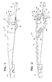
- FIGS. 1-2 and 5-7 show a wiper arm assembly 10 constructed according to one presently preferred embodiment of the invention.
- the wiper arm assembly 10 has a mounting head 12 to facilitate attachment of the assembly 10 to a vehicle, and a wiper arm 14 for operable attachment of a wiper blade (not shown) to the assembly 10.
- the wiper arm 14 is attached for articulated movement to the mounting head 12 via a hinged joint 16 so that the wiper arm 14 can be pivoted in use and during assembly to a vehicle between a preassembled position, referred to hereafter as a shipping position ( Figure 1 ), and a fully assembled position (not shown), wherein the assembly 10 is mounted to a vehicle.
- a locking mechanism 18 acts between the mounting head 12 and wiper arm 14 to prevent them from pivoting from the shipping position back toward a disassembled position ( Figure 5 ). Accordingly, the wiper arm assembly 10 is prevented from becoming inadvertently disassembled from the shipping position under a torque force, such as during shipping or while being handled prior to being attached to the vehicle.
- the mounting head 12 has a mounting portion 20 adjacent a first end 23 and a hinge portion 22 adjacent a second end 25.
- the mounting portion 20 preferably has an opening 24 to facilitate attachment of the assembly 10 to the vehicle via a standard fastener.
- the hinge portion 22 is adjacent the end 25 opposite the opening 24, and is adapted to allow the wiper arm 14 to articulate relative to the mounting head 12.
- the mounting head 12 has a pair of laterally spaced sidewalls 26, 27 defining a generally open channel 28 therebetween.
- An axle 30 of a predetermined diameter extends between the sidewalls 26, 27.
- the axle 30 preferably defines a generally cylindrical bearing surface 31 facing the end 25 and being spaced a predetermined distance from the end 25.
- the mounting head 12 has a spring attachment member, represented here, by way of example and without limitations, as a spring pin 32 extending between the sidewalls 26, 27. To further define the attachment member, a through opening 34 is preferably formed adjacent the spring pin 32. The spring pin 32 is located generally between the axle 30 and the mounting portion 20.
- the mounting head 12 preferably has at least one, and shown here as a pair of stop surfaces 36 ( Figures 2-7 ) arranged to limit the degree of pivot of the wiper arm 14 upwardly from the mounting head 12, from the fully assembled position while on the vehicle to the service-up position ( Figure 7 ). It should be recognized that the degree of movement between the assembled position and the service-up position can be varied, as desired, by altering the stop surfaces 36.
- the locking mechanism 18 is defined in part on the mounting head 12 by a locking member 38.
- the locking member 38 is represented here as extending generally between the sidewalls 26, 27 and from the axle 30 downwardly toward a bottom mounting surface 39 of the mounting head 12. It should be recognized that the locking member 38 could be separate and detached from the axle 30, if desired.
- the locking member 38 has a locking surface or surfaces 40, shown here, by way of example and without limitations, as being generally flat and extending generally perpendicular to the bottom mounting surface 39.
- the locking surfaces 40 are interrupted by the through opening 34, but otherwise extend between the sidewalls 26, 27.
- the wiper arm 14 has an elongate body extending between opposite ends 42, 44 generally along a longitudinal axis 43, with one end 42, for example, being adapted for attachment of the wiper blade, and the other end 44 being arranged for pivotal attachment to the mounting head 12.
- the wiper arm 14 has a spring attachment feature, shown here as a spring hook 46, attached to a bottom surface of the wiper arm 14, and preferably formed as one piece therewith.
- the end 44 has a pair of sidewalls 48, 49 laterally spaced from one another by a centrally extending spring channel 50.
- the sidewalls 48, 49 have outer surfaces arranged for close receipt between the sidewalls 26, 27 of the mounting head 12 and within the hinge portion 22.
- the sidewalls 48, 49 have protrusions, shown here by way of example and without limitations, as a plurality of ribs 51 ( Figure 9 ), extending outwardly therefrom and extending substantially parallel to the longitudinal axis 43 along the length of the sidewalls 48, 49.
- the end 44 has a hub 52, preferably formed as a monolithic piece of material with the wiper arm 14, although it could be formed as a separate piece and attached thereafter.
- the hub 52 is defined at least in part by a pocket 54 extending into the end 44 a predetermined distance to a seating surface 56.
- the seating surface 56 is preferably cylindrical to conform generally to the generally cylindrical bearing surface 31 on the axle 30.
- the pocket 54 is defined in part by opposite lower and upper walls 58, 59, respectively, preferably spaced from one another for close receipt of the axle 30, such that the axle 30 can oscillate within the pocket 54.
- the lower and upper walls 58, 59 are shown here, for example, as being parallel to one another.
- the sidewalls 48, 49 have protrusions 61 extending axially outwardly from the end 44 adjacent a bottom surface 71 of the wiper arm 14.
- the protrusions 61 are represented here, by way of example and without limitations, as having arcuate fillets 63 transitioning a front wall 67 to the end 44.
- the front walls 67 extend a predetermined distance axially and terminate at free ends, referred to hereafter as locking surfaces 69.
- the locking surfaces 69 are generally flat and extend generally perpendicular to the longitudinal central axis of the wiper arm 14 for abutting locking engagement with the locking surfaces 40 on the mounting head 12 while the assembly 10 is in the shipping position.
- a spring shown here as a coil spring 62, is tensioned between the mounting head 12 and the wiper arm 14.
- the coil spring 62 has hooked, generally c-shaped opposite ends 64, 65, with one end 64 being attached to the spring pin 32 of the mounting head 12 and the other end 65 being attached to the spring hook 46 of the wiper arm 14.
- the wiper arm assembly 10 is in its disassembled position ( Figure 5 ). While in the disassembled position, the wiper arm assembly 10 is able to readily fall apart.
- the axle 30 is in abutting contact with the end 44 of the wiper arm 14 adjacent the pocket 54 of the hub 52.
- the mounting head 12 and wiper arm 14 are rotated relative to one another, with the mounting head 12 moving counter clockwise, as viewed in Figure 6 , wherein the mounting head 12 and wiper arm 14 are shown in a partially assembled position.
- the axle 30 begins to enter the pocket 54 while the spring pin 32 and locking surfaces 40 extending therefrom move conjointly with the axle 30 over the protrusions 61.
- the coil spring 62 is increased in length from that of the disassembled position, thus, increasing the tension force in the spring 62.
- the mounting head 12 and wiper arm 14 are rotated further during assembly wherein the axle 30 is received in the pocket 54 so that the tension imparted by the coil spring 62 pulls the axle 30 toward the seating surface 56 of the hub 52.
- the locking surfaces 40 of the mounting head locking member 38 are pulled into engagement with locking surfaces 69 on the protrusions 61.
- the spring pin 32 preferably remains slightly spaced from the end 44 of the wiper arm 14. The locking surfaces 40, 69 remain engaged with one another while in the shipping position ( Figures 2-4 ) and the axle 30 remains captured between the walls 58, 59 of the pocket 54 and preferably engaged with the seating surface 56, all under the biasing tension of the spring 62.
- the assembly 10 is to be disassembled, translation of the mounting head 12 relative to the wiper arm 14 is required to clear the respective locking surfaces 40, 69 from engagement with one another. As such, a linear force sufficient to overcome the tensile force imparted by the spring 62 must be applied between the mounting head 12 and the wiper arm 14 to translate the axle 30 outwardly from the pocket 54 and to clear the locking surfaces 40, 69 from locked engagement with one another. Accordingly, once in the shipping position, the wiper arm assembly 10 is locked against disassembly via relative rotation of the wiper arm 14 and mounting head 12, and thus, the assembly 10 is assured of not becoming inadvertently disassembled.
- the wiper arm 14 While in the shipping position, the locking member, the wiper arm 14 is able to be pivoted upwardly from a fully assembled position while mounted on the vehicle to the service-up position ( Figure 7 ). While in the service-up position, the stop surfaces 36 engage an abutment surface 66 on the wiper arm 14 to limit the pivoting movement of the wiper arm 14 relative to the mounting head 12, while the bearing surface 31 of the axle 30 preferably remains seated against the seating surface 56 of the hub 52. Accordingly, the locking member 38 is preferably slightly spaced from the upper wall 59 of the pocket 54 while in the service-up position. Of course, if desired, the locking member 38 could be arranged to engage the upper wall 59 to define the service-up position.
- axle 30 and the hub 52 could be constructed in the reverse orientation. Accordingly, an axle 130 could be attached to a wiper arm 114, and a hub 152 could be formed or attached on a mounting head 112.
- a pocket 154 is formed in the hub 152 similarly as described above, however, it preferably extends in an inclined relation to the central axis of the assembly to facilitate the locking engagement between the mounting head 112 and the wiper arm 114 while in the shipping position.
- the hub 152 has a locking surface 140 arranged to confront another locking surface 169 on the wiper arm 114, such that the locking surfaces 140, 169 prevent the mounting head 112 from rotating relative to the wiper arm 114 toward the disassembled position. As such, the mounting head 112 and the wiper are 114 are locked against disassembly.
- a locking mechanism 218 can have a protrusion or protrusions 261 with associated locking surfaces 240 attached to a mounting head 212, and a locking surface 269 could be formed or attached on a wiper arm 214.
Landscapes
- Engineering & Computer Science (AREA)
- Mechanical Engineering (AREA)
- Connection Of Plates (AREA)
- Insertion Pins And Rivets (AREA)
- Snaps, Bayonet Connections, Set Pins, And Snap Rings (AREA)
Claims (6)
- Ensemble de bras d'essuie-glace (10), comprenant :une tête de support (12) qui présente une première extrémité (23) avec une surface inférieure (39), configurée de façon à être montée dans un véhicule, et une paire de parois latérales (26, 27) espacées de manière latérale qui s'étendent vers le haut à partir de la surface inférieure vers une seconde extrémité (25), un axe (30) s'étendant entre lesdites parois latérales (26, 27), ladite tête de support (12) présentant une surface de verrouillage plate (40) qui s'étend le long d'un plan en général perpendiculaire à ladite surface inférieure (39) ;un bras d'essuie-glace (14) qui s'étend le long d'un axe longitudinal (43) entre une première extrémité (42) configurée pour une fixation opérationnelle à une lame d'essuie-glace, et une seconde extrémité (44) qui présente un moyeu (52) avec une poche (54) qui s'étend à partir d'une extrémité ouverte, destinée à recevoir ledit axe (30) sur une surface de portée (56), ladite seconde extrémité (44) dudit bras d'essuie-glace (14) présentant une saillie (61) qui s'étend vers l'extérieur dans une direction en général opposée à ladite première extrémité (42) dudit bras d'essuie-glace (14), ladite saillie (61) présentant une surface de verrouillage plate (69) qui s'étend le long d'un plan en général perpendiculaire audit axe longitudinal (43) ;un ressort (62) agencé pour une fixation opérationnelle à ladite tête de support (12) et audit bras d'essuie-glace (14) ;dans lequel lesdites surfaces de verrouillage plates (40, 69) de ladite tête de support (12) et dudit bras d'essuie-glace (14), sont configurées de façon à être mises en prise les unes avec les autres dans une position d'expédition sous une force transmise par ledit ressort (62) lors de la rotation de ladite tête de support (12) par rapport audit bras d'essuie-glace (14) à partir d'une position démontée vers ladite position d'expédition, lesdites surfaces de verrouillage (40, 69) se faisant face les unes aux autres dans un plan en général perpendiculaire audit axe longitudinal (43) dans ladite position d'expédition, et tout en empêchant ladite tête de support (12) et ledit bras d'essuie-glace (14) de tourner en arrière vers ladite position démontée à partir de ladite position d'expédition ; etladite tête de support (12) présentant un élément de fixation de ressort (32) qui s'étend entre lesdites parois latérales (26, 27), ledit ressort (62) étant fixé audit élément de fixation de ressort (32), dans lequel ladite surface de verrouillage (40) de ladite tête de support (12) s'étend vers le bas à partir dudit élément de fixation de ressort (32) vers ladite surface inférieure (39).
- Ensemble de bras d'essuie-glace (10) selon la revendication 1, dans lequel ladite surface de verrouillage (69) dudit bras d'essuie-glace (14) fournit une extrémité libre dudit moyeu (52).
- Ensemble de bras d'essuie-glace (10) selon la revendication 1, dans lequel ledit axe (30) vient en prise avec ladite surface de portée (56) de ladite poche (54) dans ladite position d'expédition.
- Ensemble de bras d'essuie-glace (10) selon la revendication 1, dans lequel ledit moyeu (52) présente des parois latérales opposées avec des saillies qui s'étendent vers l'extérieur à partir de celles-ci destinées à les recevoir entre lesdites parois latérales (26, 27) de ladite tête de support (12).
- Ensemble de bras d'essuie-glace (10) selon la revendication 4, dans lequel lesdites saillies sont prévues sous la forme d'une pluralité de nervures allongées.
- Ensemble de bras d'essuie-glace (10) selon la revendication 5, dans lequel lesdites nervures s'étendent de manière sensiblement parallèles audit axe longitudinal (43) dudit bras d'essuie-glace (14).
Applications Claiming Priority (3)
| Application Number | Priority Date | Filing Date | Title |
|---|---|---|---|
| US86344506P | 2006-10-30 | 2006-10-30 | |
| US11/926,344 US8042219B2 (en) | 2006-10-30 | 2007-10-29 | Wiper arm assembly having locking surfaces |
| PCT/US2007/082916 WO2008055123A2 (fr) | 2006-10-30 | 2007-10-30 | Ensemble bras d'essuie-glace comprenant une surface de blocage et son procédé de fabrication |
Publications (3)
| Publication Number | Publication Date |
|---|---|
| EP2086802A2 EP2086802A2 (fr) | 2009-08-12 |
| EP2086802A4 EP2086802A4 (fr) | 2013-08-21 |
| EP2086802B1 true EP2086802B1 (fr) | 2015-04-01 |
Family
ID=39328410
Family Applications (1)
| Application Number | Title | Priority Date | Filing Date |
|---|---|---|---|
| EP07863637.0A Active EP2086802B1 (fr) | 2006-10-30 | 2007-10-30 | Ensemble bras d'essuie-glace comprenant une surface de blocage |
Country Status (6)
| Country | Link |
|---|---|
| US (1) | US8042219B2 (fr) |
| EP (1) | EP2086802B1 (fr) |
| JP (1) | JP5347131B2 (fr) |
| KR (1) | KR101375619B1 (fr) |
| CN (1) | CN101553385B (fr) |
| WO (1) | WO2008055123A2 (fr) |
Families Citing this family (10)
| Publication number | Priority date | Publication date | Assignee | Title |
|---|---|---|---|---|
| GB2479482B (en) * | 2009-01-07 | 2014-09-24 | Purrfect Fence Llc | Pivoting fencing apparatus and fencing system |
| DE102013019805B4 (de) * | 2013-11-27 | 2022-06-15 | Mercedes-Benz Group AG | Verbindungsanordnung zum Verbinden eines Wischblatts mit einem Wischarm, sowie Wischblatt und Wischarm zur Herstellung einer solchen Verbindungsanordnung |
| JP5780564B2 (ja) * | 2014-02-19 | 2015-09-16 | 日本ワイパブレード株式会社 | ワイパーアーム |
| DE102014214560A1 (de) * | 2014-07-24 | 2016-01-28 | Robert Bosch Gmbh | Sicherheitskupplung für Finray-Wischer |
| USD933574S1 (en) * | 2019-07-09 | 2021-10-19 | Trico Belgium Sa | Windshield wiper |
| USD928067S1 (en) * | 2019-07-09 | 2021-08-17 | Trico Belgium Sa | Windshield wiper |
| USD928066S1 (en) * | 2019-07-09 | 2021-08-17 | Trico Belgium Sa | Wiper assembly |
| USD974273S1 (en) * | 2019-07-09 | 2023-01-03 | Trico Belgium, SA | Windshield wiper |
| CN219523852U (zh) * | 2022-12-30 | 2023-08-15 | 台州法雷奥温岭汽车零部件有限公司 | 后雨刷器以及车辆 |
| CN117104186A (zh) * | 2023-08-02 | 2023-11-24 | 娄永超 | 一种用于机动车后视镜的雨刮器 |
Citations (10)
| Publication number | Priority date | Publication date | Assignee | Title |
|---|---|---|---|---|
| US4170804A (en) | 1978-05-15 | 1979-10-16 | Vanauto Accessories Proprietary Limited | Wiper arm and mounting head |
| US5435042A (en) | 1993-01-25 | 1995-07-25 | Nippon Wiperblade Co., Ltd. | Windshield wiper arm including a link device |
| EP0729869A1 (fr) | 1995-02-28 | 1996-09-04 | Valeo Systemes D'essuyage | Essuie-glace pour véhicule automobile comportant un bras en matière plastique rigide et léger |
| EP0845394A1 (fr) | 1996-11-28 | 1998-06-03 | Champion Spark Plug S.A. | Bras d'essuie-glace. |
| JP2001001868A (ja) | 1999-06-22 | 2001-01-09 | Asmo Co Ltd | ワイパアーム |
| JP2001080466A (ja) | 1999-09-09 | 2001-03-27 | Nifco Inc | ワイパアーム構造 |
| JP2002037036A (ja) | 2000-07-25 | 2002-02-06 | Nifco Inc | 車両用ワイパ装置 |
| US6553608B2 (en) | 2000-03-25 | 2003-04-29 | Robert Bosch Gmbh | Wiper arm for windscreen wiper |
| US6658691B2 (en) | 2001-04-06 | 2003-12-09 | Asmo Co., Ltd. | Wiper arm with rotation restriction member |
| JP2004249823A (ja) | 2003-02-20 | 2004-09-09 | Asmo Co Ltd | ワイパアーム |
Family Cites Families (26)
| Publication number | Priority date | Publication date | Assignee | Title |
|---|---|---|---|---|
| AT317701B (de) | 1971-02-04 | 1974-09-10 | Rau Swf Autozubehoer | Vorrichtung zum Befestigen eines Scheibenwischerarmes auf einer Antriebswelle, insbesondere für Kraftfahrzeuge |
| DE2853948C2 (de) | 1978-12-14 | 1987-03-26 | Robert Bosch Gmbh, 7000 Stuttgart | Wischarm zum Übertragen einer Bewegung von einem Antriebsorgan auf ein Wischblatt zum Reinigen von Kraftfahrzeugscheiben |
| US4564971A (en) | 1984-08-06 | 1986-01-21 | Trico Products Corporation | Wiper equipment |
| DE3521527C2 (de) | 1985-06-15 | 1993-10-14 | Swf Auto Electric Gmbh | Wischarm, insbesondere für Scheibenreinigungsanlagen für Kraftfahrzeuge |
| FR2584666B1 (fr) | 1985-07-10 | 1989-06-16 | Champion Spark Plug Europ | Bras moteur pour balai d'essuie-glace avec capuchon coulissant |
| JPS6317149A (ja) | 1986-07-09 | 1988-01-25 | Asmo Co Ltd | 自動車用ワイパ装置 |
| DE3714649A1 (de) | 1987-05-02 | 1988-11-10 | Swf Auto Electric Gmbh | Wischarm, insbesondere fuer scheibenwischeranlagen an kraftfahrzeugen |
| JPH0271056U (fr) | 1988-11-17 | 1990-05-30 | ||
| DE3840501A1 (de) | 1988-12-01 | 1990-06-07 | Swf Auto Electric Gmbh | Verfahren zur montage einer wischanlage und wischanlage |
| CN2171526Y (zh) * | 1993-09-17 | 1994-07-13 | 赖文乾 | 雨刷结构 |
| DE4445414B4 (de) * | 1994-12-20 | 2007-10-04 | Valeo Wischersysteme Gmbh | Verbindungsstück für eine Scheibenwischvorrichtung eines Kraftfahrzeuges |
| FR2736024B1 (fr) | 1995-06-28 | 1997-08-08 | Valeo Systemes Dessuyage | Essuie-glace de vehicule automobile muni de moyens de limitation du soulevement du bras d'essuie-glace |
| JPH10129424A (ja) | 1996-10-25 | 1998-05-19 | Kanto Auto Works Ltd | ワイパー装置 |
| JP2000064154A (ja) | 1998-08-19 | 2000-02-29 | Sulzer Rueti Ag | 直列杼口織機の緯糸挿入装置及び該装置を有する直列杼口織機 |
| DE19925388A1 (de) | 1999-06-02 | 2000-12-14 | Bosch Gmbh Robert | Abklappbarer Wischarm |
| JP2001010450A (ja) | 1999-06-29 | 2001-01-16 | Asmo Co Ltd | 車両用ワイパ装置 |
| DE19951440B4 (de) | 1999-10-25 | 2015-04-02 | Robert Bosch Gmbh | Wischarm für ein Fahrzeug |
| DE10065014A1 (de) | 2000-12-23 | 2002-07-04 | Bosch Gmbh Robert | Wischvorrichtung, insbesondere für Scheiben von Kraftfahrzeugen |
| US20020174504A1 (en) * | 2001-05-22 | 2002-11-28 | Adm 21 Co., Ltd | Adapter for windshield wiper arms |
| DE10126258A1 (de) | 2001-05-29 | 2002-12-05 | Bosch Gmbh Robert | Wischerarm, insbesondere für eine Scheibenwischvorrichtung eines Kraftfahrzeugs |
| DE10131580A1 (de) | 2001-07-02 | 2003-01-16 | Bosch Gmbh Robert | Wischerarm, insbesondere für eine Scheibenwischvorrichtung eines Kraftfahrzeugs und Verfahren zur Herstellung eines Wischerarms |
| DE10162401A1 (de) * | 2001-12-19 | 2003-07-10 | Bosch Gmbh Robert | Scheibenwischer mit einem Wischarm |
| JP2004345583A (ja) | 2003-05-26 | 2004-12-09 | Mitsuba Corp | ワイパアーム装置 |
| JP4153439B2 (ja) | 2004-01-07 | 2008-09-24 | アスモ株式会社 | ワイパアーム |
| KR100680774B1 (ko) * | 2004-12-27 | 2007-02-08 | 주식회사 캄코 | 스토퍼가 구비된 와이퍼 |
| JP4473749B2 (ja) | 2005-03-01 | 2010-06-02 | 日本ワイパブレード株式会社 | ワイパーアーム及びワイパーアーム用ストッパ部材 |
-
2007
- 2007-10-29 US US11/926,344 patent/US8042219B2/en active Active
- 2007-10-30 CN CN2007800402328A patent/CN101553385B/zh not_active Expired - Fee Related
- 2007-10-30 EP EP07863637.0A patent/EP2086802B1/fr active Active
- 2007-10-30 WO PCT/US2007/082916 patent/WO2008055123A2/fr not_active Ceased
- 2007-10-30 JP JP2009534930A patent/JP5347131B2/ja not_active Expired - Fee Related
- 2007-10-30 KR KR1020097007823A patent/KR101375619B1/ko not_active Expired - Fee Related
Patent Citations (10)
| Publication number | Priority date | Publication date | Assignee | Title |
|---|---|---|---|---|
| US4170804A (en) | 1978-05-15 | 1979-10-16 | Vanauto Accessories Proprietary Limited | Wiper arm and mounting head |
| US5435042A (en) | 1993-01-25 | 1995-07-25 | Nippon Wiperblade Co., Ltd. | Windshield wiper arm including a link device |
| EP0729869A1 (fr) | 1995-02-28 | 1996-09-04 | Valeo Systemes D'essuyage | Essuie-glace pour véhicule automobile comportant un bras en matière plastique rigide et léger |
| EP0845394A1 (fr) | 1996-11-28 | 1998-06-03 | Champion Spark Plug S.A. | Bras d'essuie-glace. |
| JP2001001868A (ja) | 1999-06-22 | 2001-01-09 | Asmo Co Ltd | ワイパアーム |
| JP2001080466A (ja) | 1999-09-09 | 2001-03-27 | Nifco Inc | ワイパアーム構造 |
| US6553608B2 (en) | 2000-03-25 | 2003-04-29 | Robert Bosch Gmbh | Wiper arm for windscreen wiper |
| JP2002037036A (ja) | 2000-07-25 | 2002-02-06 | Nifco Inc | 車両用ワイパ装置 |
| US6658691B2 (en) | 2001-04-06 | 2003-12-09 | Asmo Co., Ltd. | Wiper arm with rotation restriction member |
| JP2004249823A (ja) | 2003-02-20 | 2004-09-09 | Asmo Co Ltd | ワイパアーム |
Also Published As
| Publication number | Publication date |
|---|---|
| CN101553385B (zh) | 2012-12-19 |
| WO2008055123A3 (fr) | 2008-06-12 |
| EP2086802A4 (fr) | 2013-08-21 |
| KR20090074769A (ko) | 2009-07-07 |
| JP2010508195A (ja) | 2010-03-18 |
| JP5347131B2 (ja) | 2013-11-20 |
| EP2086802A2 (fr) | 2009-08-12 |
| KR101375619B1 (ko) | 2014-03-18 |
| WO2008055123A2 (fr) | 2008-05-08 |
| CN101553385A (zh) | 2009-10-07 |
| US20080098557A1 (en) | 2008-05-01 |
| US8042219B2 (en) | 2011-10-25 |
Similar Documents
| Publication | Publication Date | Title |
|---|---|---|
| EP2086802B1 (fr) | Ensemble bras d'essuie-glace comprenant une surface de blocage | |
| US8720035B2 (en) | Wiper arm assembly having a locking catch and method of construction | |
| JP4733148B2 (ja) | ワイパ装置 | |
| KR100928904B1 (ko) | 와이퍼 블레이드 | |
| RU2271287C2 (ru) | Стеклоочиститель | |
| US9021652B2 (en) | Connecting element for the articulated connection of a wiper blade to a wiper arm | |
| EP1256497B1 (fr) | Dispositif d'essuie-glace | |
| JP2002521270A (ja) | 自動車のウインドガラスのためのワイパブレード | |
| US7971313B2 (en) | Wiper arm assembly having a locking tab | |
| JP2004519387A (ja) | 特に自動車の板ガラス払拭装置のためのワイパアーム | |
| US8286321B2 (en) | Method of constructing a wiper arm assembly having a locking arm | |
| US8037569B2 (en) | Wiper arm assembly having a locking member | |
| CZ2001719A3 (cs) | Raménko stěrače | |
| US7610657B2 (en) | Hinge | |
| US20060191095A1 (en) | Composite buckling spring in compression spring wiper arm | |
| JP5084500B2 (ja) | ワイパーレバーとワイパーレバー支持体との間の関節装置、およびこのような関節装置を備えるワイパーアーム | |
| JP2008238868A (ja) | ワイパーブレード | |
| CN120282904A (zh) | 刮水器致动连杆系统 |
Legal Events
| Date | Code | Title | Description |
|---|---|---|---|
| PUAI | Public reference made under article 153(3) epc to a published international application that has entered the european phase |
Free format text: ORIGINAL CODE: 0009012 |
|
| 17P | Request for examination filed |
Effective date: 20090526 |
|
| AK | Designated contracting states |
Kind code of ref document: A2 Designated state(s): AT BE BG CH CY CZ DE DK EE ES FI FR GB GR HU IE IS IT LI LT LU LV MC MT NL PL PT RO SE SI SK TR |
|
| DAX | Request for extension of the european patent (deleted) | ||
| A4 | Supplementary search report drawn up and despatched |
Effective date: 20130724 |
|
| RIC1 | Information provided on ipc code assigned before grant |
Ipc: B60S 1/34 20060101AFI20130718BHEP |
|
| 17Q | First examination report despatched |
Effective date: 20140226 |
|
| GRAP | Despatch of communication of intention to grant a patent |
Free format text: ORIGINAL CODE: EPIDOSNIGR1 |
|
| INTG | Intention to grant announced |
Effective date: 20141112 |
|
| GRAS | Grant fee paid |
Free format text: ORIGINAL CODE: EPIDOSNIGR3 |
|
| GRAA | (expected) grant |
Free format text: ORIGINAL CODE: 0009210 |
|
| AK | Designated contracting states |
Kind code of ref document: B1 Designated state(s): AT BE BG CH CY CZ DE DK EE ES FI FR GB GR HU IE IS IT LI LT LU LV MC MT NL PL PT RO SE SI SK TR |
|
| REG | Reference to a national code |
Ref country code: GB Ref legal event code: FG4D |
|
| REG | Reference to a national code |
Ref country code: CH Ref legal event code: EP |
|
| REG | Reference to a national code |
Ref country code: IE Ref legal event code: FG4D |
|
| REG | Reference to a national code |
Ref country code: DE Ref legal event code: R096 Ref document number: 602007040914 Country of ref document: DE Effective date: 20150513 |
|
| REG | Reference to a national code |
Ref country code: AT Ref legal event code: REF Ref document number: 718880 Country of ref document: AT Kind code of ref document: T Effective date: 20150515 |
|
| REG | Reference to a national code |
Ref country code: NL Ref legal event code: VDEP Effective date: 20150401 |
|
| REG | Reference to a national code |
Ref country code: AT Ref legal event code: MK05 Ref document number: 718880 Country of ref document: AT Kind code of ref document: T Effective date: 20150401 |
|
| REG | Reference to a national code |
Ref country code: FR Ref legal event code: PLFP Year of fee payment: 9 |
|
| REG | Reference to a national code |
Ref country code: LT Ref legal event code: MG4D |
|
| PG25 | Lapsed in a contracting state [announced via postgrant information from national office to epo] |
Ref country code: NL Free format text: LAPSE BECAUSE OF FAILURE TO SUBMIT A TRANSLATION OF THE DESCRIPTION OR TO PAY THE FEE WITHIN THE PRESCRIBED TIME-LIMIT Effective date: 20150401 |
|
| PG25 | Lapsed in a contracting state [announced via postgrant information from national office to epo] |
Ref country code: PT Free format text: LAPSE BECAUSE OF FAILURE TO SUBMIT A TRANSLATION OF THE DESCRIPTION OR TO PAY THE FEE WITHIN THE PRESCRIBED TIME-LIMIT Effective date: 20150803 Ref country code: FI Free format text: LAPSE BECAUSE OF FAILURE TO SUBMIT A TRANSLATION OF THE DESCRIPTION OR TO PAY THE FEE WITHIN THE PRESCRIBED TIME-LIMIT Effective date: 20150401 Ref country code: CZ Free format text: LAPSE BECAUSE OF FAILURE TO SUBMIT A TRANSLATION OF THE DESCRIPTION OR TO PAY THE FEE WITHIN THE PRESCRIBED TIME-LIMIT Effective date: 20150401 Ref country code: LT Free format text: LAPSE BECAUSE OF FAILURE TO SUBMIT A TRANSLATION OF THE DESCRIPTION OR TO PAY THE FEE WITHIN THE PRESCRIBED TIME-LIMIT Effective date: 20150401 Ref country code: ES Free format text: LAPSE BECAUSE OF FAILURE TO SUBMIT A TRANSLATION OF THE DESCRIPTION OR TO PAY THE FEE WITHIN THE PRESCRIBED TIME-LIMIT Effective date: 20150401 |
|
| PG25 | Lapsed in a contracting state [announced via postgrant information from national office to epo] |
Ref country code: GR Free format text: LAPSE BECAUSE OF FAILURE TO SUBMIT A TRANSLATION OF THE DESCRIPTION OR TO PAY THE FEE WITHIN THE PRESCRIBED TIME-LIMIT Effective date: 20150702 Ref country code: LV Free format text: LAPSE BECAUSE OF FAILURE TO SUBMIT A TRANSLATION OF THE DESCRIPTION OR TO PAY THE FEE WITHIN THE PRESCRIBED TIME-LIMIT Effective date: 20150401 Ref country code: IS Free format text: LAPSE BECAUSE OF FAILURE TO SUBMIT A TRANSLATION OF THE DESCRIPTION OR TO PAY THE FEE WITHIN THE PRESCRIBED TIME-LIMIT Effective date: 20150801 Ref country code: AT Free format text: LAPSE BECAUSE OF FAILURE TO SUBMIT A TRANSLATION OF THE DESCRIPTION OR TO PAY THE FEE WITHIN THE PRESCRIBED TIME-LIMIT Effective date: 20150401 |
|
| REG | Reference to a national code |
Ref country code: DE Ref legal event code: R026 Ref document number: 602007040914 Country of ref document: DE |
|
| PLBI | Opposition filed |
Free format text: ORIGINAL CODE: 0009260 |
|
| PG25 | Lapsed in a contracting state [announced via postgrant information from national office to epo] |
Ref country code: DK Free format text: LAPSE BECAUSE OF FAILURE TO SUBMIT A TRANSLATION OF THE DESCRIPTION OR TO PAY THE FEE WITHIN THE PRESCRIBED TIME-LIMIT Effective date: 20150401 Ref country code: EE Free format text: LAPSE BECAUSE OF FAILURE TO SUBMIT A TRANSLATION OF THE DESCRIPTION OR TO PAY THE FEE WITHIN THE PRESCRIBED TIME-LIMIT Effective date: 20150401 |
|
| PLAX | Notice of opposition and request to file observation + time limit sent |
Free format text: ORIGINAL CODE: EPIDOSNOBS2 |
|
| 26 | Opposition filed |
Opponent name: VALEO SYSTEMES D'ESSUYAGE Effective date: 20160104 |
|
| PG25 | Lapsed in a contracting state [announced via postgrant information from national office to epo] |
Ref country code: RO Free format text: LAPSE BECAUSE OF NON-PAYMENT OF DUE FEES Effective date: 20150401 Ref country code: PL Free format text: LAPSE BECAUSE OF FAILURE TO SUBMIT A TRANSLATION OF THE DESCRIPTION OR TO PAY THE FEE WITHIN THE PRESCRIBED TIME-LIMIT Effective date: 20150401 Ref country code: SK Free format text: LAPSE BECAUSE OF FAILURE TO SUBMIT A TRANSLATION OF THE DESCRIPTION OR TO PAY THE FEE WITHIN THE PRESCRIBED TIME-LIMIT Effective date: 20150401 |
|
| PLBB | Reply of patent proprietor to notice(s) of opposition received |
Free format text: ORIGINAL CODE: EPIDOSNOBS3 |
|
| PG25 | Lapsed in a contracting state [announced via postgrant information from national office to epo] |
Ref country code: LU Free format text: LAPSE BECAUSE OF FAILURE TO SUBMIT A TRANSLATION OF THE DESCRIPTION OR TO PAY THE FEE WITHIN THE PRESCRIBED TIME-LIMIT Effective date: 20151030 Ref country code: SI Free format text: LAPSE BECAUSE OF FAILURE TO SUBMIT A TRANSLATION OF THE DESCRIPTION OR TO PAY THE FEE WITHIN THE PRESCRIBED TIME-LIMIT Effective date: 20150401 |
|
| REG | Reference to a national code |
Ref country code: CH Ref legal event code: PL |
|
| GBPC | Gb: european patent ceased through non-payment of renewal fee |
Effective date: 20151030 |
|
| PG25 | Lapsed in a contracting state [announced via postgrant information from national office to epo] |
Ref country code: MC Free format text: LAPSE BECAUSE OF FAILURE TO SUBMIT A TRANSLATION OF THE DESCRIPTION OR TO PAY THE FEE WITHIN THE PRESCRIBED TIME-LIMIT Effective date: 20150401 |
|
| REG | Reference to a national code |
Ref country code: IE Ref legal event code: MM4A |
|
| PG25 | Lapsed in a contracting state [announced via postgrant information from national office to epo] |
Ref country code: GB Free format text: LAPSE BECAUSE OF NON-PAYMENT OF DUE FEES Effective date: 20151030 Ref country code: LI Free format text: LAPSE BECAUSE OF NON-PAYMENT OF DUE FEES Effective date: 20151031 Ref country code: CH Free format text: LAPSE BECAUSE OF NON-PAYMENT OF DUE FEES Effective date: 20151031 |
|
| PG25 | Lapsed in a contracting state [announced via postgrant information from national office to epo] |
Ref country code: BE Free format text: LAPSE BECAUSE OF FAILURE TO SUBMIT A TRANSLATION OF THE DESCRIPTION OR TO PAY THE FEE WITHIN THE PRESCRIBED TIME-LIMIT Effective date: 20150401 |
|
| REG | Reference to a national code |
Ref country code: FR Ref legal event code: PLFP Year of fee payment: 10 |
|
| PG25 | Lapsed in a contracting state [announced via postgrant information from national office to epo] |
Ref country code: IE Free format text: LAPSE BECAUSE OF NON-PAYMENT OF DUE FEES Effective date: 20151030 |
|
| PLCK | Communication despatched that opposition was rejected |
Free format text: ORIGINAL CODE: EPIDOSNREJ1 |
|
| REG | Reference to a national code |
Ref country code: DE Ref legal event code: R100 Ref document number: 602007040914 Country of ref document: DE |
|
| PG25 | Lapsed in a contracting state [announced via postgrant information from national office to epo] |
Ref country code: BG Free format text: LAPSE BECAUSE OF FAILURE TO SUBMIT A TRANSLATION OF THE DESCRIPTION OR TO PAY THE FEE WITHIN THE PRESCRIBED TIME-LIMIT Effective date: 20150401 Ref country code: HU Free format text: LAPSE BECAUSE OF FAILURE TO SUBMIT A TRANSLATION OF THE DESCRIPTION OR TO PAY THE FEE WITHIN THE PRESCRIBED TIME-LIMIT; INVALID AB INITIO Effective date: 20071030 |
|
| PG25 | Lapsed in a contracting state [announced via postgrant information from national office to epo] |
Ref country code: CY Free format text: LAPSE BECAUSE OF FAILURE TO SUBMIT A TRANSLATION OF THE DESCRIPTION OR TO PAY THE FEE WITHIN THE PRESCRIBED TIME-LIMIT Effective date: 20150401 Ref country code: SE Free format text: LAPSE BECAUSE OF FAILURE TO SUBMIT A TRANSLATION OF THE DESCRIPTION OR TO PAY THE FEE WITHIN THE PRESCRIBED TIME-LIMIT Effective date: 20150401 |
|
| PG25 | Lapsed in a contracting state [announced via postgrant information from national office to epo] |
Ref country code: TR Free format text: LAPSE BECAUSE OF FAILURE TO SUBMIT A TRANSLATION OF THE DESCRIPTION OR TO PAY THE FEE WITHIN THE PRESCRIBED TIME-LIMIT Effective date: 20150401 Ref country code: MT Free format text: LAPSE BECAUSE OF FAILURE TO SUBMIT A TRANSLATION OF THE DESCRIPTION OR TO PAY THE FEE WITHIN THE PRESCRIBED TIME-LIMIT Effective date: 20150401 |
|
| PLBN | Opposition rejected |
Free format text: ORIGINAL CODE: 0009273 |
|
| STAA | Information on the status of an ep patent application or granted ep patent |
Free format text: STATUS: OPPOSITION REJECTED |
|
| REG | Reference to a national code |
Ref country code: FR Ref legal event code: PLFP Year of fee payment: 11 |
|
| 27O | Opposition rejected |
Effective date: 20170528 |
|
| REG | Reference to a national code |
Ref country code: DE Ref legal event code: R082 Ref document number: 602007040914 Country of ref document: DE Representative=s name: BECKER-KURIG-STRAUS PATENTANWAELTE PARTNERSCHA, DE Ref country code: DE Ref legal event code: R082 Ref document number: 602007040914 Country of ref document: DE Representative=s name: BECKER & KURIG PARTNERSCHAFT PATENTANWAELTE MB, DE Ref country code: DE Ref legal event code: R082 Ref document number: 602007040914 Country of ref document: DE Representative=s name: BECKER & KURIG PARTNERSCHAFT PATENTANWAELTE PA, DE Ref country code: DE Ref legal event code: R082 Ref document number: 602007040914 Country of ref document: DE Representative=s name: BECKER, KURIG, STRAUS, DE Ref country code: DE Ref legal event code: R081 Ref document number: 602007040914 Country of ref document: DE Owner name: FEDERAL-MOGUL LLC (N. D. GES. D. STAATES DELAW, US Free format text: FORMER OWNER: FEDERAL-MOGUL CORPORATION, SOUTHFIELD, MICH., US |
|
| REG | Reference to a national code |
Ref country code: FR Ref legal event code: PLFP Year of fee payment: 12 |
|
| PGFP | Annual fee paid to national office [announced via postgrant information from national office to epo] |
Ref country code: FR Payment date: 20190913 Year of fee payment: 13 |
|
| PGFP | Annual fee paid to national office [announced via postgrant information from national office to epo] |
Ref country code: IT Payment date: 20191009 Year of fee payment: 13 |
|
| PG25 | Lapsed in a contracting state [announced via postgrant information from national office to epo] |
Ref country code: FR Free format text: LAPSE BECAUSE OF NON-PAYMENT OF DUE FEES Effective date: 20201031 |
|
| PG25 | Lapsed in a contracting state [announced via postgrant information from national office to epo] |
Ref country code: IT Free format text: LAPSE BECAUSE OF NON-PAYMENT OF DUE FEES Effective date: 20201030 |
|
| P01 | Opt-out of the competence of the unified patent court (upc) registered |
Effective date: 20230529 |
|
| PGFP | Annual fee paid to national office [announced via postgrant information from national office to epo] |
Ref country code: DE Payment date: 20251229 Year of fee payment: 19 |