EP2087310B1 - Procédé et dispositif pour obtenir la distance entre un instrument de mesure optique et un objet testé - Google Patents
Procédé et dispositif pour obtenir la distance entre un instrument de mesure optique et un objet testé Download PDFInfo
- Publication number
- EP2087310B1 EP2087310B1 EP07845028.5A EP07845028A EP2087310B1 EP 2087310 B1 EP2087310 B1 EP 2087310B1 EP 07845028 A EP07845028 A EP 07845028A EP 2087310 B1 EP2087310 B1 EP 2087310B1
- Authority
- EP
- European Patent Office
- Prior art keywords
- under test
- distance
- optical
- object under
- image
- Prior art date
- Legal status (The legal status is an assumption and is not a legal conclusion. Google has not performed a legal analysis and makes no representation as to the accuracy of the status listed.)
- Not-in-force
Links
- 230000003287 optical effect Effects 0.000 title claims description 92
- 238000005259 measurement Methods 0.000 title claims description 57
- 238000012360 testing method Methods 0.000 title claims description 49
- 238000000034 method Methods 0.000 title claims description 24
- 230000004075 alteration Effects 0.000 claims description 19
- 238000005286 illumination Methods 0.000 claims description 18
- 201000009310 astigmatism Diseases 0.000 claims description 7
- 230000006870 function Effects 0.000 claims description 6
- 210000000695 crystalline len Anatomy 0.000 description 14
- 210000004087 cornea Anatomy 0.000 description 5
- 238000004422 calculation algorithm Methods 0.000 description 4
- 210000001747 pupil Anatomy 0.000 description 4
- 230000008859 change Effects 0.000 description 3
- 238000010586 diagram Methods 0.000 description 3
- 238000003384 imaging method Methods 0.000 description 3
- 230000008901 benefit Effects 0.000 description 2
- 230000000295 complement effect Effects 0.000 description 2
- 230000007423 decrease Effects 0.000 description 2
- 238000003708 edge detection Methods 0.000 description 2
- 230000001747 exhibiting effect Effects 0.000 description 2
- 229910044991 metal oxide Inorganic materials 0.000 description 2
- 150000004706 metal oxides Chemical class 0.000 description 2
- 238000003909 pattern recognition Methods 0.000 description 2
- 239000004065 semiconductor Substances 0.000 description 2
- 238000012876 topography Methods 0.000 description 2
- 238000012935 Averaging Methods 0.000 description 1
- 206010010071 Coma Diseases 0.000 description 1
- 235000004035 Cryptotaenia japonica Nutrition 0.000 description 1
- 102000007641 Trefoil Factors Human genes 0.000 description 1
- 235000015724 Trifolium pratense Nutrition 0.000 description 1
- 230000001594 aberrant effect Effects 0.000 description 1
- 238000004458 analytical method Methods 0.000 description 1
- 238000004364 calculation method Methods 0.000 description 1
- 238000010205 computational analysis Methods 0.000 description 1
- 239000000470 constituent Substances 0.000 description 1
- 239000000428 dust Substances 0.000 description 1
- 125000001475 halogen functional group Chemical group 0.000 description 1
- 238000007689 inspection Methods 0.000 description 1
- 239000007788 liquid Substances 0.000 description 1
- 238000004519 manufacturing process Methods 0.000 description 1
- 238000013507 mapping Methods 0.000 description 1
- 238000012067 mathematical method Methods 0.000 description 1
- 239000002184 metal Substances 0.000 description 1
- 238000012544 monitoring process Methods 0.000 description 1
- 238000012014 optical coherence tomography Methods 0.000 description 1
- 230000008569 process Effects 0.000 description 1
- 238000012545 processing Methods 0.000 description 1
- 230000001225 therapeutic effect Effects 0.000 description 1
- 210000004127 vitreous body Anatomy 0.000 description 1
Images




Classifications
-
- G—PHYSICS
- G01—MEASURING; TESTING
- G01B—MEASURING LENGTH, THICKNESS OR SIMILAR LINEAR DIMENSIONS; MEASURING ANGLES; MEASURING AREAS; MEASURING IRREGULARITIES OF SURFACES OR CONTOURS
- G01B11/00—Measuring arrangements characterised by the use of optical techniques
- G01B11/02—Measuring arrangements characterised by the use of optical techniques for measuring length, width or thickness
- G01B11/026—Measuring arrangements characterised by the use of optical techniques for measuring length, width or thickness by measuring distance between sensor and object
-
- A—HUMAN NECESSITIES
- A61—MEDICAL OR VETERINARY SCIENCE; HYGIENE
- A61B—DIAGNOSIS; SURGERY; IDENTIFICATION
- A61B3/00—Apparatus for testing the eyes; Instruments for examining the eyes
- A61B3/10—Objective types, i.e. instruments for examining the eyes independent of the patients' perceptions or reactions
- A61B3/1015—Objective types, i.e. instruments for examining the eyes independent of the patients' perceptions or reactions for wavefront analysis
-
- G—PHYSICS
- G01—MEASURING; TESTING
- G01M—TESTING STATIC OR DYNAMIC BALANCE OF MACHINES OR STRUCTURES; TESTING OF STRUCTURES OR APPARATUS, NOT OTHERWISE PROVIDED FOR
- G01M11/00—Testing of optical apparatus; Testing structures by optical methods not otherwise provided for
- G01M11/02—Testing optical properties
- G01M11/0221—Testing optical properties by determining the optical axis or position of lenses
-
- A—HUMAN NECESSITIES
- A61—MEDICAL OR VETERINARY SCIENCE; HYGIENE
- A61B—DIAGNOSIS; SURGERY; IDENTIFICATION
- A61B3/00—Apparatus for testing the eyes; Instruments for examining the eyes
- A61B3/10—Objective types, i.e. instruments for examining the eyes independent of the patients' perceptions or reactions
- A61B3/1005—Objective types, i.e. instruments for examining the eyes independent of the patients' perceptions or reactions for measuring distances inside the eye, e.g. thickness of the cornea
Definitions
- This invention relates generally to the field of optical measurement instruments, such as eye examination instruments, and more particularly an apparatus and method for measuring or computing the distance from an object under test (e.g., an eye) to an optical or mechanical reference plane of a measurement instrument.
- optical measurement instruments such as eye examination instruments
- Optical measurement instruments such as instruments which measure the optical properties of the human eye, rely on the correct working distance being set between a reference plane of the instrument and a reference plane of the object being measured, so that the best possible imaging conditions are met, resulting in the highest possible accuracy of the instrument.
- a misalignment of this distance (hereinafter referred to as the "Z-Distance”) can result in measurement inaccuracies.
- the result can be a misinterpretation of the radius of curvature of either a surface or waves of light, or error in measurement of other parameters such as ocular refraction, higher order aberrations or pupil size.
- These inaccuracies will furthermore be of unknown magnitude, due to the unknown error in the Z-distance.
- EP 1 223 406 A discloses monitoring distance variations with an astigmatic zone plate system.
- US 5,165,063 discloses a device for measuring distances using an optical element of large chromatic aberration.
- EP 0 142 464 discloses a method of determining a position of an object.
- Disclosed below are systems and methods that utilize an aberration introduced by an optical system to determine the Z-Distance of an optical measurement system to an object under test, such as an eye or other optical system or component.
- FIG. 1 illustrates a system 100 for measuring the distance from a reference plane 105 for an optical measurement instrument to a reference plane 15 of an object under test 10.
- System 100 includes an illumination system 110, an optical system 120, an optical sensor 130, a processor 140, and memory 150.
- System 100 may be integrated with an optical measurement instrument, or may be configured as a standalone system that can be employed at the start of an optical measurement to determine the distance from the reference plane 105 for the optical measurement instrument to a reference plane 15 of object under test 10 (hereinafter referred to as "the Z-Distance") to maintain the accuracy of measurements made by the optical measurement instrument.
- the reference plane 105 for the optical measurement instrument can be chosen as any plane that is convenient for measurement purposes. In one embodiment, the reference plane 105 may pass through optical system 120.
- Illumination system 110 illuminates object under test 10 with a predetermined pattern comprising one or more sources of light.
- An exemplary embodiment of illumination system 110 will be described in greater detail below with respect to FIGs. 3 and 4 .
- Optical system 120 introduces an aberration into a received light pattern such that at least one aspect of the light pattern and/or the one or more sources of light varies asymmetrically, for example, varies asymmetrically about a nominal Z-Distance ("D NOM ”) in orthogonal first and second directions. That is, as the light pattern, and individual sources therein, passes through optical system 120, at least one aspect of the light pattern and/or sources change differently in the X-direction ("into the page" in FIG. 1 ) than it does in the Y-direction as the Z-Distance changes, for example, from being less than some nominal distance D NOM to being greater than D NOM .
- D NOM nominal Z-Distance
- illumination system 110 illuminates object under test 10 with light having a predetermined pattern. At least a portion of the pattern of light that illuminates object under test 10 is scattered or reflected or both toward optical system 120. Optical system 120 produces an aberrated image of the predetermined pattern or portion or light source thereof, as described above.
- Optical sensor 130 receives the aberrated image produced by optical system 120 and outputs detected image data.
- Optical sensor 130 may comprise a photoreceptive sensor, such as a charge-coupled device (CCD) or a complementary metal oxide semiconductor (CMOS) detector.
- CCD charge-coupled device
- CMOS complementary metal oxide semiconductor
- Processor 140 receives the detected image data and uses the detected image data to determine the Z-Distance. In particular, processor 140 determines the Z-Distance based on an aspect of an aberrated image of the light pattern and/or the individual sources contained therein. In one embodiment, a characteristic of the sensed light is compared to reference data stored in memory 150. In that case, an object having a known radius of curvature may be used to generate at least one set of reference data as a function of the distance between reference plane 105 and the object having the known radius of curvature. For ease of comparison, the reference data may be fitted to a reference curve using a polynomial function or other convenient function.
- FIGs. 2A-B illustrate one embodiment 200 of the system of FIG. 1 .
- FIG. 2A is a view of system 200 in a first plane labeled the YZ-plane.
- FIG. 2B is a view of system 200 in a second plane, labeled the XZ-plane, that is perpendicular to the first plane.
- System 200 includes an illumination system 210, an optional window 222, an optical element 224, a lens 226, an optical sensor 230, and a processor (not shown in FIGs. 2A-B ) and memory (also not shown in FIGs. 2A-B ).
- the optical element 224 comprises a plate beamsplitter that is tilted relative to a system optical axis. As perhaps best seen in FIG. 2A , plate beamsplitter 224 is tilted in the Z-direction.
- the optical element 224 may be replace by, or used to approximate, any combination of optics of an optical system, for example, a combination of optics forming at least part of a wavefront measurement system and/or a topographic measurement system.
- system 200 may be integrated with an optical measurement instrument, or may be configured as a standalone system that can be employed at the start of a measurement to determine the Z-Distance to maintain the accuracy of measurements made by the optical measurement instrument.
- Illumination system 210 illuminates object under test 10 with a predetermined pattern.
- An exemplary embodiment of illumination system 110 and 210 will be described in greater detail below with respect to FIGs. 3 and 4 .
- the combination of plate beamsplitter 224 and lens 226 produce an aberrated image of the light pattern and/or the individual sources contained therein.
- the "length" or size of the light pattern changes differently in the X-direction than it does in the Y-direction as the Z-Distance changes from being less than some nominal distance D NOM to being greater than D NOM .
- Astigmatism is a difference in effective lens power along different meridians.
- the lens 226 and beamsplitter combination 224 effectively has different focal lengths in the YZ plane than for the XZ plane.
- the aberration introduced into an image of the light pattern may be as simple as a single spot of light, a plurality of spots of light, or an extended source.
- the light pattern may also comprised of a collection of smaller light patterns.
- the analysis for calculating distance may be applied to the entire pattern, or to the individual constituents or sources making up the light pattern.
- the astigmatic element creates an image of the source 210 onto the sensor 230 which has finite size corresponding to the rays that are in proper focus.
- the lens 226 and beamsplitter 224 combination effectively has a slightly smaller focal length in the YZ plane than in the XY plane.
- the image of the source 210 in the XZ plane will achieve a focus when the test object 210 is slightly closer to the instrument (Z-distance is shorter than Dnom).
- the image of the source 210 will achieve optimal focus when the object is slightly further from the instrument (Z-distance is longer than Dnom).
- the shape of the image changes as the object is moved closer and further from the instrument. That is, when the object is closer than the nominal distance, then the aberrated image is smaller in the x-direction and larger in the y-direction. When the object is slightly further, then the image is slightly larger in the x-direction and slightly smaller in the Y-direction.
- the image is arranged so that the image appears approximately symmetrical in x- and y. This is called the circle of least confusion, and is well known to those skilled in the art.
- the actual z-distance from some physical instrument component may in general be different from this reference plane, however, it is straightforward to add the appropriate offset to the measurement distance if needed as this would be just a constant offset.
- Optical sensor 230 receives and senses the light from lens 226 and outputs detected image data.
- Optical sensor 230 may comprise a photoreceptive sensor, such as a charge-coupled device (CCD) or a complementary metal oxide semiconductor (CMOS) detector.
- CCD charge-coupled device
- CMOS complementary metal oxide semiconductor
- a processor receives the detected image data and uses the detected image data to determine the Z-Distance.
- processor 140 determines the Z-Distance based on the astigmatism of the light sensed by optical sensor 230.
- FIG. 3 illustrates an illumination system 300 that may be employed in the illumination systems 110, 210 of FIGs. 1 and 2A-B .
- FIG. 4 is a cross-section of the illumination source of FIG. 3 .
- illumination system 300 may comprise an infrared or low power visible emitter, a diffuser to provide a predetermined intensity distribution, and an aperture forming source 301 of defined dimensions.
- the source 301 may be dimensioned to form or approximate a point source.
- one or more source 301 may be dimensioned to form an extended source, for example, to provide additional information, of the test object and/or an optical system.
- the source 301 is much smaller than a reference distance, for example, the z-distance in FIGS.
- Illumination system 300 may comprise only one spot 301, or a ring of several spots 301, for example, to obtain an average value, which decreases ambiguities due to varying ambient light conditions or manufacturing tolerances of the light emitting device.
- a pattern of spots is shown to provide for averaging, while covering a symmetric area around the optical axis of the optical measurement instrument and maintaining an equal distance of each spot to the axis.
- the spot-source 301 shown in FIG. 4 can be provided for each of the apertures in the mount shown in FIG. 3 .
- each spot is first reflected by the cornea, which in a simple approximation acts as a spherical mirror, to form a virtual image behind the mirror.
- This image created by reflected irradiation off the anterior surface of the cornea is also known as the first Purkinje Image (PKI), which for the vast majority of human eyes lies very near the iris plane.
- PKI Purkinje Image
- a focused PKI brings the optical measuring instrument into the working distance if the goal is to image to a plane conjugate to the iris or exit pupil of the eye, as in a wavefront aberrometer system. If this is not the case, as in a corneal topographer or Keratometer, the offset to that plane can be applied using statistical values which are widely available in published literature.
- the virtual image or PKI then acts as a source itself and is imaged onto optical sensor 130 or 230. In doing so, it passes through an aberrating optical system, such as optical system 120 or the system comprising the combination of plate beamsplitter 234 and lens 236, and optionally window 222.
- an aberrating optical system such as optical system 120 or the system comprising the combination of plate beamsplitter 234 and lens 236, and optionally window 222.
- FIGs. 5A-C illustrate possible image patterns generated by the arrangement of FIGs. 1 or 2A-B for various Z-Distances. Depending on the position of the eye relative to the focal plane or nominal Z-Distance, different patterns of individual spot images are possible on optical sensor 130/230.
- FIG. 5A shows an example where the Z-Distance is less than a nominal distance, D NOM .
- FIG. 5C shows an example where the Z-Distance is greater than the nominal distance, D NOM .
- FIG. 5B shows an example where the Z-Distance is about equal to the nominal distance, D NOM .
- an aspect of one or more spots in a image are measured and analyzed to determine a distance of an object from an optical system.
- certain spots may be selected based on the value of a figure of merit related to the quality of the spot images.
- data for two or more spots are combined to provide a better measurement of the distance between the object and the optical system.
- one or more aspects of an overall image pattern formed by two or more imaged spots from an illuminating source pattern are measured. The measurement data may be used in combination with data for individually imaged spots, for example, to enhance the distance measurement and/or to obtain other information about the system or test object, such as the shape of the test object or an aberration of the test object.
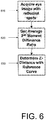
- FIG. 6 illustrates one embodiment of a method of determining the Z-Distance using the arrangement in FIGs. 2A-B .
- image data is collected by optical sensor 230.
- a characteristic is determined for the senses image.
- an average 2 nd moment difference ratio may be calculated for the sensed image, as explained in greater detail below.
- the 2 nd moment difference ratio and/or other information is compared to reference data, for example by mapping 2 nd moment difference ratio to Z-Distance, as explained in further detail below.
- FIG. 7 illustrates one embodiment of a method of determining second moments for each spot of an image sensed by optical sensor 230 in FIGs. 2A-B .
- image data is collected by optical sensor 230.
- spots are located using the image data.
- areas of interest (AOIs) are defined around each spot.
- centroid is found for each spot.
- the second moment is calculated for each spot.
- Computational analysis of the image data from optical sensor 230 can be employed to locate each spot and allow for setting of areas of interest and the computation of centroids.
- the spot size in X and Y directions can be computed.
- One convenient mathematical method for calculating the spot size is to use the 2 nd moment calculation method.
- the average second moment difference ratio DR is calculated for a plurality of light spots by, for example, using a ring of light spots as illustrated above in FIG. 3 .
- a user positions the system 200 into a range around a nominal working distance, where the imaged spots are defocused, for example, to a degree where they can be reliably located by pattern recognition or edge detection algorithms. For this purpose this is implemented in a "live" mode, where the user of the instrument can adjust the distance while inspecting the in-range or out-of-range condition on a display.
- the spots are located and the 2nd Moments for each spot, or selected spots, are calculated using Equations 2a-2b above, for example by a processor connected to an output of optical sensor 230 such as the processor 140 of FIG. 1 .
- the second moment difference ratio is calculated as in Equation 3.
- the second moment difference ratio depends uniquely upon the Z-Distance, and so the Z-Distance can be determined with fit polynomial coefficients describing a reference curve, as explained below.
- FIG. 8 is a graph showing one embodiment of a reference curve obtained from measured reference data exhibiting a relationship between second moment ratio and Z-distance in the system of FIGs. 2A-B .
- This graph can be experimentally obtained for one or more objects under test with a known radius of curvature.
- These can be a set of calibrated metal ball bearings obtained from a ball bearing gauge set.
- the range of radii of curvature can include the statistical range of radii of curvature of human corneas.
- the 2nd moment difference ratio data versus Z-Distance is calculated for one or more known spheres and stored in memory (e.g., memory 150) as reference data.
- the references data can be used to generate one or more analytical curves, for example with an n order polynomial fit, as illustrated in Equation (4).
- derived data such as that provided by Equation (3) or illustrated in FIG. 8 is used to determine when an object is within a predetermined range. For example, using the curve illustrated in FIG. 8 , if the calculated 2 nd moment difference ratio for a given measurement falls within a range of -0.2 to +0.3, than an "in range" signal may be generated to inform a user that an object or subject is located at a suitable distance for making a diagnostic measurement of the object or subject (e.g., for making a wavefront or topographic measurement). If the calculated 2 nd moment difference ratio for a given measurement is less than -0.2, then a "too close” signal may be generated to inform a user that an object or subject is located too close to make a diagnostic measurement of the object or subject. Conversely, if the calculated 2 nd moment difference ratio for a given measurement is greater than +0.3, then a "too far” may be generated to inform a user that an object or subject is located too far away to make a diagnostic measurement of the object or subject.
- data such as that provided by Equation (3) or illustrated in FIG. 8 is used to make a more accurate measurement than that provided in the previous paragraph.
- an exact value of a calculated 2 nd moment difference ratio may be used to determine a distance of an object from an optical system.
- such information may be used alone or in combination with other data (e.g., an overall shape or other aspect of the spot illustrated in FIG. 5 ) to refine or enhance the distance measurement, for example, by determining or estimating a shape or aberration of the test object.
- one or more new equations, equation parameters, or and/or corrected reference curves similar to that shown in FIG. 8 may be calculated so as to allow a refined or more accurate distance measurement to be made.
- FIG. 9 illustrates another embodiment of a method of determining Z-Distance using the arrangement in FIG. 1 .
- a step 910 an object under test is illuminated.
- a step 920 light from the object under test is passed through an optical system which produces an aberrated image that changes such that an aspect of the image varies between when the distance is greater than a nominal distance D NOM and when the distance is less than D NOM , the variation being different in a first direction than in a second direction perpendicular to the first direction.
- the aberrated image is sensed with an optical sensor.
- a step 940 the distance from the reference plane of the optical measurement instrument to the reference plane of the object under test is determined based on a measured aspect of the aberrated image sensed by the optical sensor.
- FIG. 10 depicts an optical ray trace diagram of an embodiment of the present invention.
- the lens 1026 and beamsplitters 1024 and 1025 are shown widely separated.
- the position of the beamsplitters1024 and 1025 relative to the lens 1026 or object under test 1005 is relatively unimportant.
- the source 1010 in this case is located near the first beamsplitter 1025 as a matter of convenience, but is not constrained to this location.
- the spot diagrams 1040, 1045, 1050 illustrate the change is shape at the sensor 1030 a test object 1005 is moved relative to the beamsplitter 1025.
- a reference distance is set to correspond to the distance between the test object 1005 and the beamsplitter 1025 that produces the smallest focus (e.g., illustrated by the spot diagram 1045).
- astigmatism was used as the exemplary aberration.
- aberrations that may be introduced by, for example, the systems in FIGS. 1 , 2A , 2B , or 10 , and/or added to the imaging path of these systems that could accomplish the desired objective.
- an added aberration or combination of aberrations create images that are different in appearance or in a particular aspect as the instrument is moved closer vs. further from the object under test.
- Defocus for example, would not generally provide the needed information, since it adds an aberration to the images that is symmetrically disposed about the desired plane, thus making it more difficult for an algorithm to correctly indicate which direction the instrument should be adjusted to obtain a desired position.
- a spherical aberration could be substituted or added to obtain the desired result.
- the appearance of the spot images would change asymmetrically as the instrument is moved relative to the object under test in one direction or another relative to a reference distance.
- the images generally appear as rings when (for example) the instrument is too close and as bright spots with halos when (for example) the instrument is too far.
- Other potential aberrations include but are not limited to coma, trefoil, or any other aberration that changes the image asymmetrically.
- Embodiments of the system and method described above can be employed with a variety of optical measurement instruments such as eye examination instruments, including ophthalmic diagnostic and/or therapeutic instruments.
- eye examination instruments include wavefront aberrometers, autorefractors, corneal topographers and other instruments which require the knowledge of precise distance of the measurement device to a reference plane of the optical system under test, to perform measurements such as wavefront measurement of the human eye, topography of a human cornea or optical coherence tomography of the human cornea, vitreous humor and lens.
- the object under test can be, but is not limited to, a human eye, a contact lens, an intraocular lens (IOL), or another object in a wet (hydrated and/or containing liquid film on its surface) or dry state. With 5 the true distance to the object under test, or the difference between the true distance and a nominal distance, being known, then measurement results can be recomputed or corrected to achieve the highest possible measurement accuracy.
Landscapes
- Physics & Mathematics (AREA)
- Health & Medical Sciences (AREA)
- Life Sciences & Earth Sciences (AREA)
- General Physics & Mathematics (AREA)
- Molecular Biology (AREA)
- General Health & Medical Sciences (AREA)
- Engineering & Computer Science (AREA)
- Biomedical Technology (AREA)
- Heart & Thoracic Surgery (AREA)
- Medical Informatics (AREA)
- Biophysics (AREA)
- Surgery (AREA)
- Animal Behavior & Ethology (AREA)
- Ophthalmology & Optometry (AREA)
- Public Health (AREA)
- Veterinary Medicine (AREA)
- Chemical & Material Sciences (AREA)
- Analytical Chemistry (AREA)
- Length Measuring Devices By Optical Means (AREA)
- Eye Examination Apparatus (AREA)
- Optical Radar Systems And Details Thereof (AREA)
Claims (17)
- Procédé de mesure d'une distance entre un plan de référence d'un instrument de mesure optique et un plan de référence d'un objet soumis à essai, comprenant :- l'éclairage de l'objet soumis à essai (10) avec une source (110) afin de former une image virtuelle ;- le passage de la lumière en provenance de l'objet soumis à essai à travers un système optique (120) ayant au moins une aberration optique ;- la production d'une image avec aberration de l'image virtuelle ;- l'acquisition de l'image avec aberration avec un capteur optique (130) ; et- la détermination de la distance entre le plan de référence de l'instrument de mesure optique et le plan de référence de l'objet soumis à essai en se basant sur un aspect de l'image avec aberration acquise par le capteur optique.
- Procédé selon la revendication 1, l'éclairage de l'objet soumis à essai comprenant l'éclairage de l'objet soumis à essai avec un motif lumineux comprenant au moins deux sources, de préférence en dirigeant un motif symétrique de points lumineux sur l'objet soumis à essai.
- Procédé selon la revendication 1 ou 2, l'objet soumis à essai étant soit un oeil humain, soit l'une parmi une lentille intraoculaire et une lentille de contact.
- Procédé selon l'une quelconque des revendications précédentes, l'instrument optique étant un instrument de diagnostic ophtalmique ou optométrique.
- Procédé selon l'une quelconque des revendications précédentes, le système optique comprenant un élément astigmatique qui applique un astigmatisme à la lumière en provenance de l'objet soumis à essai.
- Procédé selon l'une quelconque des revendications précédentes, le passage de la lumière en provenance de l'objet soumis à essai à travers le système optique comprenant :- le passage de la lumière à travers un séparateur de faisceau à lame incliné dans une troisième direction perpendiculaire aux première et deuxième directions ; et- le passage de la lumière en provenance du séparateur de faisceau à travers une lentille (226).
- Procédé selon l'une quelconque des revendications précédentes, comprenant en outre l'utilisation d'un objet ayant un rayon de courbure connu pour générer au moins un ensemble de données de référence en tant que fonction de la distance entre le plan de référence de l'instrument de mesure optique et l'objet ayant le rayon de courbure connu, la détermination de la distance entre le plan de référence de l'instrument de mesure optique et le plan de référence du dispositif optique soumis à essai comprenant la comparaison d'une caractéristique de l'image avec aberration acquise par le capteur optique aux données de référence.
- Procédé selon l'une quelconque des revendications précédentes, comprenant en outre le réglage de la position relative de l'objet soumis à essai par rapport à l'instrument jusqu'à ce qu'une valeur souhaitée soit obtenue.
- Procédé selon l'une quelconque des revendications précédentes, l'aspect de l'image avec aberration variant entre le cas où la distance est supérieure à une distance nominale DNOM et le cas où la distance est inférieure à DNOM, la variation dans une première direction étant différente à celle dans une deuxième direction perpendiculaire à la première direction.
- Système de mesure d'une distance entre un plan de référence d'un instrument de mesure optique et un plan de référence d'un objet soumis à essai, comprenant :- un système d'éclairage (110) configuré pour éclairer l'objet soumis à essai (10) afin de former une image virtuelle ;- un système optique (120) configuré pour recevoir de la lumière en provenance de l'objet soumis à essai et pour produire soit une image astigmatique, soit une image avec aberration de l'image virtuelle ;- un capteur optique (130) configuré pour recevoir et acquérir l'image ; et- un processeur (140) configuré pour déterminer la distance entre le plan de référence de l'instrument de mesure optique et le plan de référence de l'objet en se basant sur un aspect de l'image acquise par le capteur optique.
- Système selon la revendication 10, le système d'éclairage comprenant un motif lumineux comprenant au moins deux sources, de préférence un motif de sources de lumière, de préférence un motif symétrique de sources de lumière, plus de préférence disposées en un anneau.
- Système selon la revendication 10 ou 11, l'objet soumis à essai étant soit un dispositif optique, soit un oeil humain, soit l'une parmi une lentille intraoculaire et une lentille de contact.
- Système selon l'une quelconque des revendications 10 à 12, l'objet étant un instrument de diagnostic ophtalmique ou optométrique.
- Système selon l'une quelconque des revendications 10 à 13, le système optique comprenant un élément astigmatique qui applique un astigmatisme à la lumière en provenance de l'objet soumis à essai.
- Système selon l'une quelconque des revendications 10 à 14, comprenant en outre une mémoire destinée à stocker des données de référence pour une pluralité de distances entre le plan de référence de l'instrument de mesure optique et un objet ayant un rayon de courbure connu.
- Système selon l'une quelconque des revendications 10 à 15, l'aspect de l'image avec aberration étant un rapport d'aspect de l'image avec aberrationou un rapport de différence de 2ème moment ; ou le processeur étant configuré pour calculer un rapport de différence de 2ème moment DR de l'image astigmatique du motif de lumière, avec

- Système selon la revendication 16, le système optique comprenant :- un séparateur de faisceau à lame incliné dans une troisième direction perpendiculaire aux première et deuxième directions ; et- une lentille (226) disposée pour recevoir la lumière en provenance du séparateur de faisceau à lame.
Applications Claiming Priority (2)
| Application Number | Priority Date | Filing Date | Title |
|---|---|---|---|
| US85777606P | 2006-11-09 | 2006-11-09 | |
| PCT/US2007/084334 WO2008058281A2 (fr) | 2006-11-09 | 2007-11-09 | Procédé et dispositif pour obtenir la distance entre un instrument de mesure optique et un objet testé |
Publications (2)
| Publication Number | Publication Date |
|---|---|
| EP2087310A2 EP2087310A2 (fr) | 2009-08-12 |
| EP2087310B1 true EP2087310B1 (fr) | 2018-08-15 |
Family
ID=39322226
Family Applications (1)
| Application Number | Title | Priority Date | Filing Date |
|---|---|---|---|
| EP07845028.5A Not-in-force EP2087310B1 (fr) | 2006-11-09 | 2007-11-09 | Procédé et dispositif pour obtenir la distance entre un instrument de mesure optique et un objet testé |
Country Status (5)
| Country | Link |
|---|---|
| US (1) | US7887184B2 (fr) |
| EP (1) | EP2087310B1 (fr) |
| AU (1) | AU2007317262B2 (fr) |
| CA (1) | CA2669336C (fr) |
| WO (1) | WO2008058281A2 (fr) |
Families Citing this family (13)
| Publication number | Priority date | Publication date | Assignee | Title |
|---|---|---|---|---|
| US7556378B1 (en) | 2003-04-10 | 2009-07-07 | Tsontcho Ianchulev | Intraoperative estimation of intraocular lens power |
| ES2665536T3 (es) | 2004-04-20 | 2018-04-26 | Alcon Research, Ltd. | Microscopio quirúrgico y sensor de frente de onda integrados |
| US8333474B2 (en) * | 2007-10-19 | 2012-12-18 | Wavetec Vision Systems, Inc. | Optical instrument alignment system |
| US7594729B2 (en) | 2007-10-31 | 2009-09-29 | Wf Systems, Llc | Wavefront sensor |
| US8550624B2 (en) | 2008-11-06 | 2013-10-08 | Wavetec Vision Systems, Inc. | Optical angular measurement system for ophthalmic applications and method for positioning of a toric intraocular lens with increased accuracy |
| US8876290B2 (en) | 2009-07-06 | 2014-11-04 | Wavetec Vision Systems, Inc. | Objective quality metric for ocular wavefront measurements |
| CN102497833B (zh) | 2009-07-14 | 2014-12-03 | 波技术视觉系统公司 | 眼科手术测量系统 |
| EP2818130B1 (fr) | 2009-07-14 | 2017-09-27 | WaveTec Vision Systems, Inc. | Détermination de la position de lentille efficace d'une lentille intraoculaire à l'aide d'une puissance de réfraction aphaque |
| CN102081697B (zh) | 2009-11-27 | 2013-12-11 | 深圳迈瑞生物医疗电子股份有限公司 | 一种在超声成像空间中定义感兴趣容积的方法及其装置 |
| US9072462B2 (en) | 2012-09-27 | 2015-07-07 | Wavetec Vision Systems, Inc. | Geometric optical power measurement device |
| US10568764B2 (en) | 2013-03-14 | 2020-02-25 | Amo Development, Llc | System and methods for depth detection in laser-assisted ophthalmic procedures |
| KR101386248B1 (ko) * | 2013-09-09 | 2014-04-17 | 재단법인 실감교류인체감응솔루션연구단 | 공간 제스처 인식 장치 및 방법 |
| EP4311475A1 (fr) * | 2022-07-25 | 2024-01-31 | Ellex Medical Pty. Ltd. | Dispositif et procédé de détermination de l'emplacement d'un objet d'intérêt dans un il d'un patient, et appareil ophtalmique |
Family Cites Families (4)
| Publication number | Priority date | Publication date | Assignee | Title |
|---|---|---|---|---|
| CH663466A5 (fr) * | 1983-09-12 | 1987-12-15 | Battelle Memorial Institute | Procede et dispositif pour determiner la position d'un objet par rapport a une reference. |
| CH671828A5 (fr) | 1987-06-26 | 1989-09-29 | Battelle Memorial Institute | |
| US6002484A (en) | 1999-06-18 | 1999-12-14 | Rozema; Jos J. | Phase contrast aberroscope |
| GB0101002D0 (en) * | 2001-01-13 | 2001-02-28 | Rolls Royce Plc | Monitoring distance variations |
-
2007
- 2007-11-09 WO PCT/US2007/084334 patent/WO2008058281A2/fr not_active Ceased
- 2007-11-09 CA CA2669336A patent/CA2669336C/fr not_active Expired - Fee Related
- 2007-11-09 US US11/938,145 patent/US7887184B2/en active Active
- 2007-11-09 AU AU2007317262A patent/AU2007317262B2/en not_active Ceased
- 2007-11-09 EP EP07845028.5A patent/EP2087310B1/fr not_active Not-in-force
Non-Patent Citations (1)
| Title |
|---|
| None * |
Also Published As
| Publication number | Publication date |
|---|---|
| US7887184B2 (en) | 2011-02-15 |
| WO2008058281A3 (fr) | 2008-07-10 |
| US20080291396A1 (en) | 2008-11-27 |
| AU2007317262A1 (en) | 2008-05-15 |
| CA2669336A1 (fr) | 2008-05-15 |
| WO2008058281A2 (fr) | 2008-05-15 |
| AU2007317262B2 (en) | 2011-10-20 |
| EP2087310A2 (fr) | 2009-08-12 |
| CA2669336C (fr) | 2015-08-04 |
Similar Documents
| Publication | Publication Date | Title |
|---|---|---|
| US7887184B2 (en) | Method and apparatus for obtaining the distance from an optical measurement instrument to an object under test | |
| US7988290B2 (en) | Systems and methods for measuring the shape and location of an object | |
| US6273566B1 (en) | Ophthalmologic characteristic measuring apparatus | |
| US7341348B2 (en) | Moiré aberrometer | |
| US7303281B2 (en) | Method and device for determining refractive components and visual function of the eye for vision correction | |
| US9713420B2 (en) | Optical instrument alignment system | |
| US7311400B2 (en) | Determining clinical refraction of eye | |
| US7284858B2 (en) | Method for determining distances in the anterior ocular segment | |
| US6598973B2 (en) | Spatial filter for enhancing Hartmann-Shack images and associated methods | |
| US20060158612A1 (en) | Apparatus and method for topographical parameter measurements | |
| JPWO2003022138A1 (ja) | 眼光学特性測定装置 | |
| JP3813557B2 (ja) | 眼特性測定装置 | |
| US6676258B2 (en) | Eye characteristic measurement apparatus with speckle noise reduction | |
| JP6435322B2 (ja) | 生物の光学系の収差を測定する装置および方法 |
Legal Events
| Date | Code | Title | Description |
|---|---|---|---|
| PUAI | Public reference made under article 153(3) epc to a published international application that has entered the european phase |
Free format text: ORIGINAL CODE: 0009012 |
|
| 17P | Request for examination filed |
Effective date: 20090511 |
|
| AK | Designated contracting states |
Kind code of ref document: A2 Designated state(s): AT BE BG CH CY CZ DE DK EE ES FI FR GB GR HU IE IS IT LI LT LU LV MC MT NL PL PT RO SE SI SK TR |
|
| DAX | Request for extension of the european patent (deleted) | ||
| 17Q | First examination report despatched |
Effective date: 20161215 |
|
| GRAP | Despatch of communication of intention to grant a patent |
Free format text: ORIGINAL CODE: EPIDOSNIGR1 |
|
| INTG | Intention to grant announced |
Effective date: 20180308 |
|
| GRAS | Grant fee paid |
Free format text: ORIGINAL CODE: EPIDOSNIGR3 |
|
| GRAA | (expected) grant |
Free format text: ORIGINAL CODE: 0009210 |
|
| AK | Designated contracting states |
Kind code of ref document: B1 Designated state(s): AT BE BG CH CY CZ DE DK EE ES FI FR GB GR HU IE IS IT LI LT LU LV MC MT NL PL PT RO SE SI SK TR |
|
| REG | Reference to a national code |
Ref country code: CH Ref legal event code: EP Ref country code: GB Ref legal event code: FG4D Ref country code: AT Ref legal event code: REF Ref document number: 1030294 Country of ref document: AT Kind code of ref document: T Effective date: 20180815 |
|
| REG | Reference to a national code |
Ref country code: IE Ref legal event code: FG4D |
|
| REG | Reference to a national code |
Ref country code: DE Ref legal event code: R096 Ref document number: 602007055782 Country of ref document: DE |
|
| REG | Reference to a national code |
Ref country code: FR Ref legal event code: PLFP Year of fee payment: 12 |
|
| REG | Reference to a national code |
Ref country code: NL Ref legal event code: FP |
|
| REG | Reference to a national code |
Ref country code: LT Ref legal event code: MG4D |
|
| PGFP | Annual fee paid to national office [announced via postgrant information from national office to epo] |
Ref country code: NL Payment date: 20181114 Year of fee payment: 12 |
|
| REG | Reference to a national code |
Ref country code: AT Ref legal event code: MK05 Ref document number: 1030294 Country of ref document: AT Kind code of ref document: T Effective date: 20180815 |
|
| PG25 | Lapsed in a contracting state [announced via postgrant information from national office to epo] |
Ref country code: FI Free format text: LAPSE BECAUSE OF FAILURE TO SUBMIT A TRANSLATION OF THE DESCRIPTION OR TO PAY THE FEE WITHIN THE PRESCRIBED TIME-LIMIT Effective date: 20180815 Ref country code: IS Free format text: LAPSE BECAUSE OF FAILURE TO SUBMIT A TRANSLATION OF THE DESCRIPTION OR TO PAY THE FEE WITHIN THE PRESCRIBED TIME-LIMIT Effective date: 20181215 Ref country code: SE Free format text: LAPSE BECAUSE OF FAILURE TO SUBMIT A TRANSLATION OF THE DESCRIPTION OR TO PAY THE FEE WITHIN THE PRESCRIBED TIME-LIMIT Effective date: 20180815 Ref country code: GR Free format text: LAPSE BECAUSE OF FAILURE TO SUBMIT A TRANSLATION OF THE DESCRIPTION OR TO PAY THE FEE WITHIN THE PRESCRIBED TIME-LIMIT Effective date: 20181116 Ref country code: AT Free format text: LAPSE BECAUSE OF FAILURE TO SUBMIT A TRANSLATION OF THE DESCRIPTION OR TO PAY THE FEE WITHIN THE PRESCRIBED TIME-LIMIT Effective date: 20180815 Ref country code: BG Free format text: LAPSE BECAUSE OF FAILURE TO SUBMIT A TRANSLATION OF THE DESCRIPTION OR TO PAY THE FEE WITHIN THE PRESCRIBED TIME-LIMIT Effective date: 20181115 Ref country code: LT Free format text: LAPSE BECAUSE OF FAILURE TO SUBMIT A TRANSLATION OF THE DESCRIPTION OR TO PAY THE FEE WITHIN THE PRESCRIBED TIME-LIMIT Effective date: 20180815 |
|
| PG25 | Lapsed in a contracting state [announced via postgrant information from national office to epo] |
Ref country code: LV Free format text: LAPSE BECAUSE OF FAILURE TO SUBMIT A TRANSLATION OF THE DESCRIPTION OR TO PAY THE FEE WITHIN THE PRESCRIBED TIME-LIMIT Effective date: 20180815 Ref country code: ES Free format text: LAPSE BECAUSE OF FAILURE TO SUBMIT A TRANSLATION OF THE DESCRIPTION OR TO PAY THE FEE WITHIN THE PRESCRIBED TIME-LIMIT Effective date: 20180815 |
|
| PGFP | Annual fee paid to national office [announced via postgrant information from national office to epo] |
Ref country code: GB Payment date: 20181107 Year of fee payment: 12 Ref country code: CH Payment date: 20181115 Year of fee payment: 12 Ref country code: FR Payment date: 20181011 Year of fee payment: 12 |
|
| PG25 | Lapsed in a contracting state [announced via postgrant information from national office to epo] |
Ref country code: RO Free format text: LAPSE BECAUSE OF FAILURE TO SUBMIT A TRANSLATION OF THE DESCRIPTION OR TO PAY THE FEE WITHIN THE PRESCRIBED TIME-LIMIT Effective date: 20180815 Ref country code: CZ Free format text: LAPSE BECAUSE OF FAILURE TO SUBMIT A TRANSLATION OF THE DESCRIPTION OR TO PAY THE FEE WITHIN THE PRESCRIBED TIME-LIMIT Effective date: 20180815 Ref country code: EE Free format text: LAPSE BECAUSE OF FAILURE TO SUBMIT A TRANSLATION OF THE DESCRIPTION OR TO PAY THE FEE WITHIN THE PRESCRIBED TIME-LIMIT Effective date: 20180815 Ref country code: PL Free format text: LAPSE BECAUSE OF FAILURE TO SUBMIT A TRANSLATION OF THE DESCRIPTION OR TO PAY THE FEE WITHIN THE PRESCRIBED TIME-LIMIT Effective date: 20180815 Ref country code: IT Free format text: LAPSE BECAUSE OF FAILURE TO SUBMIT A TRANSLATION OF THE DESCRIPTION OR TO PAY THE FEE WITHIN THE PRESCRIBED TIME-LIMIT Effective date: 20180815 |
|
| REG | Reference to a national code |
Ref country code: DE Ref legal event code: R097 Ref document number: 602007055782 Country of ref document: DE |
|
| PG25 | Lapsed in a contracting state [announced via postgrant information from national office to epo] |
Ref country code: DK Free format text: LAPSE BECAUSE OF FAILURE TO SUBMIT A TRANSLATION OF THE DESCRIPTION OR TO PAY THE FEE WITHIN THE PRESCRIBED TIME-LIMIT Effective date: 20180815 Ref country code: SK Free format text: LAPSE BECAUSE OF FAILURE TO SUBMIT A TRANSLATION OF THE DESCRIPTION OR TO PAY THE FEE WITHIN THE PRESCRIBED TIME-LIMIT Effective date: 20180815 |
|
| PLBE | No opposition filed within time limit |
Free format text: ORIGINAL CODE: 0009261 |
|
| STAA | Information on the status of an ep patent application or granted ep patent |
Free format text: STATUS: NO OPPOSITION FILED WITHIN TIME LIMIT |
|
| 26N | No opposition filed |
Effective date: 20190516 |
|
| PG25 | Lapsed in a contracting state [announced via postgrant information from national office to epo] |
Ref country code: MC Free format text: LAPSE BECAUSE OF FAILURE TO SUBMIT A TRANSLATION OF THE DESCRIPTION OR TO PAY THE FEE WITHIN THE PRESCRIBED TIME-LIMIT Effective date: 20180815 Ref country code: LU Free format text: LAPSE BECAUSE OF NON-PAYMENT OF DUE FEES Effective date: 20181109 |
|
| REG | Reference to a national code |
Ref country code: BE Ref legal event code: MM Effective date: 20181130 |
|
| REG | Reference to a national code |
Ref country code: IE Ref legal event code: MM4A |
|
| PG25 | Lapsed in a contracting state [announced via postgrant information from national office to epo] |
Ref country code: SI Free format text: LAPSE BECAUSE OF FAILURE TO SUBMIT A TRANSLATION OF THE DESCRIPTION OR TO PAY THE FEE WITHIN THE PRESCRIBED TIME-LIMIT Effective date: 20180815 |
|
| PG25 | Lapsed in a contracting state [announced via postgrant information from national office to epo] |
Ref country code: IE Free format text: LAPSE BECAUSE OF NON-PAYMENT OF DUE FEES Effective date: 20181109 |
|
| PG25 | Lapsed in a contracting state [announced via postgrant information from national office to epo] |
Ref country code: BE Free format text: LAPSE BECAUSE OF NON-PAYMENT OF DUE FEES Effective date: 20181130 |
|
| PG25 | Lapsed in a contracting state [announced via postgrant information from national office to epo] |
Ref country code: MT Free format text: LAPSE BECAUSE OF NON-PAYMENT OF DUE FEES Effective date: 20181109 |
|
| PGFP | Annual fee paid to national office [announced via postgrant information from national office to epo] |
Ref country code: DE Payment date: 20191029 Year of fee payment: 13 |
|
| PG25 | Lapsed in a contracting state [announced via postgrant information from national office to epo] |
Ref country code: TR Free format text: LAPSE BECAUSE OF FAILURE TO SUBMIT A TRANSLATION OF THE DESCRIPTION OR TO PAY THE FEE WITHIN THE PRESCRIBED TIME-LIMIT Effective date: 20180815 |
|
| PG25 | Lapsed in a contracting state [announced via postgrant information from national office to epo] |
Ref country code: PT Free format text: LAPSE BECAUSE OF FAILURE TO SUBMIT A TRANSLATION OF THE DESCRIPTION OR TO PAY THE FEE WITHIN THE PRESCRIBED TIME-LIMIT Effective date: 20180815 |
|
| PG25 | Lapsed in a contracting state [announced via postgrant information from national office to epo] |
Ref country code: CY Free format text: LAPSE BECAUSE OF FAILURE TO SUBMIT A TRANSLATION OF THE DESCRIPTION OR TO PAY THE FEE WITHIN THE PRESCRIBED TIME-LIMIT Effective date: 20180815 Ref country code: HU Free format text: LAPSE BECAUSE OF FAILURE TO SUBMIT A TRANSLATION OF THE DESCRIPTION OR TO PAY THE FEE WITHIN THE PRESCRIBED TIME-LIMIT; INVALID AB INITIO Effective date: 20071109 |
|
| REG | Reference to a national code |
Ref country code: CH Ref legal event code: PL |
|
| REG | Reference to a national code |
Ref country code: NL Ref legal event code: MM Effective date: 20191201 |
|
| PG25 | Lapsed in a contracting state [announced via postgrant information from national office to epo] |
Ref country code: LI Free format text: LAPSE BECAUSE OF NON-PAYMENT OF DUE FEES Effective date: 20191130 Ref country code: CH Free format text: LAPSE BECAUSE OF NON-PAYMENT OF DUE FEES Effective date: 20191130 |
|
| GBPC | Gb: european patent ceased through non-payment of renewal fee |
Effective date: 20191109 |
|
| PG25 | Lapsed in a contracting state [announced via postgrant information from national office to epo] |
Ref country code: NL Free format text: LAPSE BECAUSE OF NON-PAYMENT OF DUE FEES Effective date: 20191201 |
|
| PG25 | Lapsed in a contracting state [announced via postgrant information from national office to epo] |
Ref country code: GB Free format text: LAPSE BECAUSE OF NON-PAYMENT OF DUE FEES Effective date: 20191109 Ref country code: FR Free format text: LAPSE BECAUSE OF NON-PAYMENT OF DUE FEES Effective date: 20191130 |
|
| REG | Reference to a national code |
Ref country code: DE Ref legal event code: R119 Ref document number: 602007055782 Country of ref document: DE |
|
| PG25 | Lapsed in a contracting state [announced via postgrant information from national office to epo] |
Ref country code: DE Free format text: LAPSE BECAUSE OF NON-PAYMENT OF DUE FEES Effective date: 20210601 |