EP2087368B1 - Procédé et système permettant de détecter des sources de signaux dans un espace de surveillance - Google Patents
Procédé et système permettant de détecter des sources de signaux dans un espace de surveillance Download PDFInfo
- Publication number
- EP2087368B1 EP2087368B1 EP07827303.4A EP07827303A EP2087368B1 EP 2087368 B1 EP2087368 B1 EP 2087368B1 EP 07827303 A EP07827303 A EP 07827303A EP 2087368 B1 EP2087368 B1 EP 2087368B1
- Authority
- EP
- European Patent Office
- Prior art keywords
- signal source
- frequency
- peak
- fourier transform
- dimensional fourier
- Prior art date
- Legal status (The legal status is an assumption and is not a legal conclusion. Google has not performed a legal analysis and makes no representation as to the accuracy of the status listed.)
- Active
Links
Images


Classifications
-
- G—PHYSICS
- G01—MEASURING; TESTING
- G01S—RADIO DIRECTION-FINDING; RADIO NAVIGATION; DETERMINING DISTANCE OR VELOCITY BY USE OF RADIO WAVES; LOCATING OR PRESENCE-DETECTING BY USE OF THE REFLECTION OR RERADIATION OF RADIO WAVES; ANALOGOUS ARRANGEMENTS USING OTHER WAVES
- G01S3/00—Direction-finders for determining the direction from which infrasonic, sonic, ultrasonic or electromagnetic waves, or particle emission, not having a directional significance, are being received
- G01S3/02—Direction-finders for determining the direction from which infrasonic, sonic, ultrasonic or electromagnetic waves, or particle emission, not having a directional significance, are being received using radio waves
- G01S3/74—Multi-channel systems specially adapted for direction-finding, i.e. having a single antenna system capable of giving simultaneous indications of the directions of different signals
-
- G—PHYSICS
- G01—MEASURING; TESTING
- G01S—RADIO DIRECTION-FINDING; RADIO NAVIGATION; DETERMINING DISTANCE OR VELOCITY BY USE OF RADIO WAVES; LOCATING OR PRESENCE-DETECTING BY USE OF THE REFLECTION OR RERADIATION OF RADIO WAVES; ANALOGOUS ARRANGEMENTS USING OTHER WAVES
- G01S3/00—Direction-finders for determining the direction from which infrasonic, sonic, ultrasonic or electromagnetic waves, or particle emission, not having a directional significance, are being received
- G01S3/02—Direction-finders for determining the direction from which infrasonic, sonic, ultrasonic or electromagnetic waves, or particle emission, not having a directional significance, are being received using radio waves
- G01S3/14—Systems for determining direction or deviation from predetermined direction
- G01S3/46—Systems for determining direction or deviation from predetermined direction using antennas spaced apart and measuring phase or time difference between signals therefrom, i.e. path-difference systems
- G01S3/48—Systems for determining direction or deviation from predetermined direction using antennas spaced apart and measuring phase or time difference between signals therefrom, i.e. path-difference systems the waves arriving at the antennas being continuous or intermittent and the phase difference of signals derived therefrom being measured
Definitions
- This invention relates to surveillance systems, and more specifically to methods for determining parameters of a source of electromagnetic radiation.
- Surveillance systems are used for continuous detection and tracking of signals emitted by a signal source in a region of space under surveillance.
- the signals are received by an antenna array directed towards the space under surveillance and processed to determine signal parameters such as frequency and azimuth direction.
- the signal source may be an active stationary or moving transmitter that transmits EM radiation, such as radio transmitter, wireless telephone and so on. It may also be a passive source corresponding to a reflected signal, such as a signal that originates from an active transmitter and is picked up and subsequently reflected by a radar antenna or any other radiation source. So far as the present invention is concerned, it is immaterial whether the signal source is active or passive.
- the signals received by the receiving antenna array are processed so as to distinguish genuine signals from noise and to determine the frequency, amplitude and direction of each detected signal.
- U.S. patent No. 4649392 discloses a system that simultaneously determines the frequency and direction of arrival of incoming signals.
- the apparatus of this invention comprises a layered half space dispersive delay line which is utilized as a beam forming element in a device that performs a two-dimensional Fourier transform on a function which is both time and space dependent.
- a pulse appears at the end of the delay line at a time which corresponds to the frequency of the incoming signal and the position of the pulse along the edge of the delay line is related to the direction of arrival of the incoming signals.
- U.S. patent No. 4646099 suggests a technique by which signals from antenna elements of a rectangular array are translated in frequency by mixers fed from a chirped local oscillator.
- the resultant signals are fed to the first of two groups of two-dimensional delay lines connected in series at right angles to each other.
- the two-dimensional delay lines are dispersive, having a linear relationship of delay to frequency, and the sweep rate of the local oscillator is such that the signals caused by a given frequency component at the mixer input ports are completely compressed in time when they reach the output ports of the delay lines of the second group.
- the device performs a three-dimensional Fourier transformation from time and two spatial dimensions to temporal frequency and two dimensions of spatial frequency.
- the output of the device can readily be interpreted as indicating the direction of the source and the frequency at which it is radiating.
- a problem with hitherto proposed detection systems is that detection of weak signals is difficult, thus imposing severe restrictions on the maximum distance from the antenna array for which signal detection is possible. Moreover, known systems are unable to distinguish between signals of identical frequency originating from signal sources that are spatial disposed in different directions.
- the present invention provides a method according to claim 1 and system according to claim 9 for determining electromagnetic properties of a signal source such as frequency and azimuth angle detected in a space under surveillance.
- the method and system according to the invention may be used when neither the number of signal sources, nor the frequency and direction of the signal sources are known a priori to the system.
- the system of the invention comprises an array of antenna elements.
- Signal sources in the surveillance space radiate electromagnetic (EM) signals towards the receiving antenna array which collects the radiated signals.
- the frequency f of the EM radiation may or may not be known to the system.
- the antenna array must, of course, be capable of receiving the signals and to this end must be tuned to a frequency band in which the signal sources are located and must be adapted to receive a signal over a wide angle of view that contains all the signal sources.
- the distance traveled by the EM radiation from the object to the antenna array is in general different for each receiving antenna in the array.
- the signals arriving at each of the receiving antennas are thus out of phase from each other, the phase difference being a function of the incremental distance that each signal travels before being received.
- the signals are sampled to yield a two dimensional array of sampled values that is input to an azimuth determination processing stage.
- the azimuth determination processing involves calculating a two dimensional Fourier transform of the input array.
- the Fourier transform has one index (or "bin number") j that is a function of the frequency f of the EM radiation, and various parameters of the system.
- the other bin number of the Fourier transform, k is a function of the frequency f , the azimuth angle ⁇ and parameters of the system.
- the Fourier transform is scanned for peaks satisfying predetermined criteria in order to identify signals in the surveillance space and to segregate these signals from clutter. For each received signal, if the frequency f of its EM radiation is unknown to the system, the frequency f is determined from the bin number j of the peak. The azimuth angle ⁇ of the received signal is then determined from the bin number k of the peak and the frequency f .
- Fig. 1 is a block diagram schematically showing the hardware components and signal processing stages of a detection system 20 in accordance with one embodiment of the invention.
- the system 20 comprises an antenna array 21 consisting of a plurality of wideband antenna elements A. Four antenna elements A 0 to A 3 are shown in Fig.1 . This is by way of example only, and although the invention may be carried out using any number of receiving antennas greater than 1, the greater the number of receiving antennas in the array 21, the greater is the accuracy and sensitivity of the detection and consequently of the azimuth determination.
- Signal sources in the surveillance space such as transmitters 22 to 25 (shown in Fig. 2 ) radiate electromagnetic (EM) pulses towards the receiving antenna array 21 which collects the received data.
- EM electromagnetic
- Fig. 2 shows schematically an arrangement of the antenna array 21 in which adjacent receiving antennas are aligned along an axis 30 and separated by a fixed distance d.
- the distance from the array 21 to a signal source detected in the surveillance space, such as the transmitters 22 to 25 is sufficiently large, in comparison to the length of the array 21 that the respective rays R from each antenna in the array to the transmitters are essentially parallel, and thus determine the same azimuth angle ⁇ with the axis 30.
- the signals S i,n have respective time delays i ⁇ t owing to the fact that the distance that each signal S i,n travels along the respective ray 32 from the transmitter to the antenna A i is different for each signal.
- each antenna A receives its respective signal S that is provided to its respective receiver channel RC.
- the sequence S i,n is a sampling of the signal emitted by the respective signal source 22 to 25 at a sampling rate equal to 1/ ⁇ t.
- the two dimensional array S i,n is input to an azimuth determination processing stage 11.
- the azimuth determination processing involves calculating a two dimensional Fourier transform of the array S i,n .
- the Fourier transform referred to herein as a " frequency-azimuth plot ", is a two-dimensional array F jk .
- the array F jk is scanned in the azimuth determination processing stage 11 for peaks satisfying one or more predetermined criteria in order to identify signals emitted by the signal sources 22 to 25 in the surveillance space and to segregate these signals from clutter.
- the predetermined criteria may include, for example, peak amplitude above a predetermined threshold.
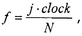
- the frequency f of each identified signal source is determined from the bin number j of the peak using Equation (5). This produces a value of f whose accuracy is determined by the number of bins N.
- the accuracy of the frequency determination can often be improved by using phase data, as is known in the art of Fourier analysis.
- the method of the invention may be performed at least twice using different values of " clock " and/or by using an RF filter.
- the azimuth angle ⁇ of the signal source is then determined from the bin number k of the peak using Equation (7).
- the output 26 of the processing stage 11 includes the azimuth angle for each detected signal and optionally the frequency of each detected signal.
- Fig. 3 shows a two-dimensional frequency-azimuth plot 35 obtained on real data by the method of the invention.
- the data were collected using a linear array of 128 receivers.
- the plot was obtained using 512 signal samples.
- the plot 35 has two peaks 36 and 37 corresponding to two different signal sources in the surveillance area.
- the peak 36 reveals a signal having a frequency of f 1 and an azimuth angle of 30°. This signal was detected with a signal to noise ration of -18 db.
- the peak 37 reveals a signal having a frequency of f 2 and an azimuth angle of 50°. This signal was detected with a signal to noise ratio of -20db.
- Increasing the number of detectors in the array enhances sensitivity.
- Fig 4 is a flow diagram summarizing the principal operations carried out in accordance with an embodiment of the invention for determining the azimuth angle and frequency of a signal source as described above with particular reference to Figs. 1 to 3 .
- system of the invention may be implemented using more than one array of receiving antennas.
- the invention may be implemented using two mutually perpendicular arrays of receiving antennas.
- An additional Fourier transform of the two-dimensional Fourier transform F jk then generates, for each identified emitter, two independent angles (azimuth and elevation) that together define a position vector of the signal source.
- the signal source need not be an active transmitter but could, for example, be a reflected signal.
- signals detected by the detector array according to the invention are spatially separated in two-dimensional space, signals having identical frequencies but spaced apart in two-dimensional space will be discretely detected.
- Discrete Fourier Transform may be employed to track the detected transmitter thus saving processing time.
- system may be a suitably programmed computer.
- the invention contemplates a computer program being readable by a computer for executing the method of the invention.
- the invention further contemplates a machine-readable memory tangibly embodying a program of instructions executable by the machine for executing the method of the invention.
Landscapes
- Physics & Mathematics (AREA)
- Engineering & Computer Science (AREA)
- General Physics & Mathematics (AREA)
- Radar, Positioning & Navigation (AREA)
- Remote Sensing (AREA)
- Radar Systems Or Details Thereof (AREA)
Claims (17)
- Procédé de traitement de signaux multiples provenant d'une ou plusieurs sources dans un espace de surveillance, le procédé étant caractérisé par :i. la réception de signaux multiples provenant d'un espace de surveillance à chaque antenne d'une pluralité d'antennes large bande à faisceau large qui sont espacées dans un réseau linéaire selon des espacements fixes ;ii. la mise en oeuvre d'une pluralité de canaux récepteurs connectés respectivement à ladite pluralité d'antennes large bande à faisceau large pour échantillonner simultanément, à un taux d'échantillonnage prédéterminé, les signaux respectifs reçus par chacune des antennes large bande à faisceau large ; et la génération d'un réseau bidimensionnel de valeurs échantillonnées Si,n correspondant à des signaux reçus par les antennes, où Si,n est le n ième échantillon du signal reçu par une antenne i et échantillonné par un canal récepteur i ;iii. le calcul d'une transformée de Fourier bidimensionnelle Fjk du réseau bidimensionnel de valeurs échantillonnées Si,n , la transformée de Fourier bidimensionnelle ayant un nombre bin j qui est une fonction de la fréquence et un nombre bin k qui est une fonction aussi bien de la fréquence f que d'un azimut ;iv. l'identification de pics dans la transformée de Fourier qui répondent à un ou plusieurs critères prédéterminés, un pic qui répond aux critères prédéterminés indiquant une source de signal dans l'espace de surveillance, moyennant quoi le nombre bin j du pic dans ladite transformée de Fourier bidimensionnelle Fjk indique la fréquence de la source de signal respective, l'amplitude du pic indique l'amplitude de la source de signal, et le nombre bin k du pic dans ladite transformée de Fourier bidimensionnelle Fjk est une fonction de ladite fréquence de la source de signal respective et de l'azimut de ladite source de signal respective ;v. la détermination de la fréquence de la source de signal respective à partir du nombre bin j du pic dans ladite transformée de Fourier bidimensionnelle Fjk ; etvi. la mise en oeuvre des opérations ii. à v. au moins deux fois en utilisant différents taux d'échantillonnage ou un filtre RF, et la détermination inéquivoque conséquente de ladite fréquence de la source de signal ; etvii. la détermination dudit azimut de ladite source de signal respective sur base de la fréquence déterminée de la source de signal respective et du nombre bin k du pic dans la transformée de Fourier bidimensionnelle Fjk ;ce qui détermine un paramètre électromagnétique et une disposition spatiale respectifs d'un ou plusieurs signaux source dans un espace de surveillance bombardé simultanément par des signaux multiples.
- Procédé selon la revendication 1, comprenant le calcul de la fréquence de la radiation émise par la source de signal indiquée par un pic identifié qui répond à un ou plusieurs critères prédéterminés, en utilisant une opération algébrique qui implique le taux d'échantillonnage.
- Procédé selon la revendication 2, comprenant le calcul de la fréquence de la radiation émise par la source de signal indiquée par le pic identifié en utilisant l'expression algébrique

- Procédé selon l'une quelconque des revendications 1 à 3, comprenant le calcul d'un angle d'azimut de la source de signal indiquée par un pic identifié qui répond à un ou plusieurs critères prédéterminés.
- Procédé selon la revendication 4, dans lequel l'angle d'azimut de la source de signal est calculé en utilisant une expression algébrique qui implique la fréquence f de la radiation émise par la source de signal.
- Procédé selon la revendication 5, dans lequel l'angle d'azimut θ de la source de signal indiquée par le pic est calculé en utilisant l'expression algébrique

- Procédé selon l'une quelconque des revendications 1 à 6, dans lequel les valeurs de Si,n sont réglées à 1 quand Si,n > 0 et à -1 quand Si,n ≤ 0.
- Procédé selon l'une quelconque des revendications 1 à 7, dans lequel les signaux multiples sont reçus par un réseau d'antennes bidimensionnel, de telle sorte que selon chacun de deux axes mutuellement perpendiculaires, les antennes respectives desdites antennes sont espacées dans un réseau linéaire selon des espacements fixes ; le procédé comprenant en outre :le calcul d'une transformée de Fourier additionnelle de ladite transformée de Fourier bidimensionnelle Fjk de manière à calculer une transformée de Fourier tridimensionnelle qui procure également l'altitude de chaque source de signal respective.
- Système de traitement de signaux multiples provenant d'une ou plusieurs sources dans un espace de surveillance, le système étant caractérisé par :une pluralité d'antennes large bande à faisceau large qui sont espacées dans un réseau linéaire à espacements fixes, configurées et utilisables pour recevoir des signaux multiples provenant d'une ou plusieurs sources dans un espace de surveillance ;une pluralité de canaux récepteurs respectivement connectables à ladite pluralité d'antennes large bande à faisceau large, dans lequel les canaux de ladite pluralité de canaux récepteurs sont configurés et utilisables pour échantillonner simultanément des signaux respectifs reçus par chaque antenne de ladite pluralité d'antennes large bande à faisceau large ; etun processeur accouplé à la pluralité de canaux récepteurs, configuré et utilisable pour mettre en oeuvre les opérations suivantes :i. utilisation de ladite pluralité de canaux récepteurs pour échantillonner simultanément, à un taux d'échantillonnage prédéterminé, les signaux respectifs reçus par chacune des antennes large bande à faisceau large, et génération d'un réseau bidimensionnel de valeurs échantillonnées Si,n , où Si,n est le nième échantillon du signal reçu par une antenne i et échantillonné sur le canal récepteur i ;ii. calcul d'une transformée de Fourier bidimensionnelle Fjk du réseau Si,n , la transformée de Fourier bidimensionnelle ayant un nombre bin j qui est une fonction de la fréquence et un nombre bin k qui est une fonction aussi bien de la fréquence f que d'un azimut ; etiii. identification de pics dans la transformée de Fourier qui répondent à un ou plusieurs critères prédéterminés, un pic qui répond aux critères prédéterminés indiquant une source de signal dans l'espace de surveillance, moyennant quoi le nombre bin j du pic dans ladite transformée de Fourier bidimensionnelle Fjk indique la fréquence de la source de signal respective, l'amplitude du pic indique l'amplitude de la source de signal, etle nombre bin k du pic dans ladite transformée de Fourier bidimensionnelle Fjk est une fonction de ladite fréquence de la source de signal respective et de l'azimut de ladite source de signal respective ;iv. détermination de la fréquence de la source de signal respective à partir du nombre bin j du pic dans ladite transformée de Fourier bidimensionnelle Fjk ;v. mise en oeuvre des opérations i. à iv. au moins deux fois en utilisant différents taux d'échantillonnage ou un filtre RF, et détermination inéquivoque conséquente de ladite fréquence de la source de signal ; etvi. détermination dudit azimut de ladite source de signal respective sur base de la fréquence déterminée de la source de signal respective et du nombre bin k du pic dans la transformée de Fourier bidimensionnelle Fjk ;le système permettant ainsi de déterminer un paramètre électromagnétique et une disposition spatiale respectifs d'un ou plusieurs signaux source dans un espace de surveillance bombardé simultanément par des signaux multiples.
- Système selon la revendication 9, dans lequel le processeur est en outre configuré pour calculer, pour un pic identifié qui répond à un ou plusieurs critères prédéterminés, la fréquence de la radiation émise par les antennes indiquées par le pic en utilisant une opération algébrique qui implique le taux d'échantillonnage.
- Système selon la revendication 10, dans lequel les antennes sont agencées dans un réseau linéaire présentant un espacement uniforme d entre des détecteurs adjacents, et dans lequel le processeur est configuré pour calculer la fréquence de la radiation émise par la source de signal indiquée par le pic en utilisant l'expression algébrique
- Système selon l'une quelconque des revendications 9 à 11, dans lequel le processeur est en outre configuré pour calculer, pour un pic identifié qui répond à un ou plusieurs critères prédéterminés, un angle d'azimut de la source de signal indiquée par le pic.
- Système selon la revendication 12, dans lequel le processeur est configuré pour calculer l'angle d'azimut de la source de signal en utilisant une expression algébrique qui implique la fréquence f de la radiation émise par la source de signal.
- Système selon la revendication 13, dans lequel le processeur est configuré pour calculer l'angle d'azimut θ de la source de signal indiquée par le pic en utilisant l'expression algébrique

- Système selon l'une quelconque des revendications 9 à 14, dans lequel les valeurs de Si,n sont réglées à 1 quand Si,n > 0 et à -1 quand Si,n ≤ 0.
- Programme informatique comprenant un moyen de codage de programme informatique configuré pour mettre en oeuvre le procédé de l'une quelconque des revendications 1 à 8 lorsque ledit programme est exécuté sur un ordinateur.
- Programme informatique selon la revendication 16 incorporé sur un support lisible par un ordinateur.
Priority Applications (1)
| Application Number | Priority Date | Filing Date | Title |
|---|---|---|---|
| EP14163068.1A EP2752679A3 (fr) | 2006-11-12 | 2007-10-31 | Procédé et système permettant de détecter des sources de signaux dans un espace de surveillance |
Applications Claiming Priority (2)
| Application Number | Priority Date | Filing Date | Title |
|---|---|---|---|
| IL179186A IL179186A0 (en) | 2006-11-12 | 2006-11-12 | Method and system for detecting signal soures in a surveillance space |
| PCT/IL2007/001329 WO2008059476A1 (fr) | 2006-11-12 | 2007-10-31 | Procédé et système permettant de détecter des sources de signaux dans un espace de surveillance |
Related Child Applications (2)
| Application Number | Title | Priority Date | Filing Date |
|---|---|---|---|
| EP14163068.1A Division EP2752679A3 (fr) | 2006-11-12 | 2007-10-31 | Procédé et système permettant de détecter des sources de signaux dans un espace de surveillance |
| EP14163068.1A Division-Into EP2752679A3 (fr) | 2006-11-12 | 2007-10-31 | Procédé et système permettant de détecter des sources de signaux dans un espace de surveillance |
Publications (2)
| Publication Number | Publication Date |
|---|---|
| EP2087368A1 EP2087368A1 (fr) | 2009-08-12 |
| EP2087368B1 true EP2087368B1 (fr) | 2014-06-11 |
Family
ID=39046781
Family Applications (2)
| Application Number | Title | Priority Date | Filing Date |
|---|---|---|---|
| EP14163068.1A Withdrawn EP2752679A3 (fr) | 2006-11-12 | 2007-10-31 | Procédé et système permettant de détecter des sources de signaux dans un espace de surveillance |
| EP07827303.4A Active EP2087368B1 (fr) | 2006-11-12 | 2007-10-31 | Procédé et système permettant de détecter des sources de signaux dans un espace de surveillance |
Family Applications Before (1)
| Application Number | Title | Priority Date | Filing Date |
|---|---|---|---|
| EP14163068.1A Withdrawn EP2752679A3 (fr) | 2006-11-12 | 2007-10-31 | Procédé et système permettant de détecter des sources de signaux dans un espace de surveillance |
Country Status (6)
| Country | Link |
|---|---|
| US (2) | US8022874B2 (fr) |
| EP (2) | EP2752679A3 (fr) |
| KR (1) | KR101435168B1 (fr) |
| AU (1) | AU2007320792B2 (fr) |
| IL (2) | IL179186A0 (fr) |
| WO (1) | WO2008059476A1 (fr) |
Families Citing this family (17)
| Publication number | Priority date | Publication date | Assignee | Title |
|---|---|---|---|---|
| WO2006044476A2 (fr) * | 2004-10-12 | 2006-04-27 | Robert Vernon Vanman | Procede et systeme de surveillance mobile et d'enregistrement d'evenement |
| US8982944B2 (en) * | 2005-10-12 | 2015-03-17 | Enforcement Video, Llc | Method and system for categorized event recording of images in multiple resolution levels |
| US8599368B1 (en) | 2008-01-29 | 2013-12-03 | Enforcement Video, Llc | Laser-based speed determination device for use in a moving vehicle |
| US8228364B2 (en) * | 2008-01-29 | 2012-07-24 | Enforcement Video, Llc | Omnidirectional camera for use in police car event recording |
| WO2009102480A2 (fr) | 2008-02-15 | 2009-08-20 | Enforcement Video, Llc | Système et procédé de stockage d’images multirésolution |
| KR101562904B1 (ko) * | 2009-06-12 | 2015-10-23 | 삼성전자주식회사 | 도래각 측정 장치 및 방법 |
| US8736680B1 (en) | 2010-05-18 | 2014-05-27 | Enforcement Video, Llc | Method and system for split-screen video display |
| IL221162A (en) | 2012-07-29 | 2017-06-29 | Elta Systems Ltd | A device for receiving and transmitting electromagnetic signals |
| DE102013111633B4 (de) * | 2012-11-06 | 2021-04-01 | Electronics And Telecommunications Research Institute | Verfahren und Vorrichtung für Funkortung |
| IL223619A (en) | 2012-12-13 | 2017-08-31 | Elta Systems Ltd | A system and method for coherent processing of signals from transmission and / or reception systems |
| US9706298B2 (en) | 2013-01-08 | 2017-07-11 | Stmicroelectronics S.R.L. | Method and apparatus for localization of an acoustic source and acoustic beamforming |
| US9759807B2 (en) * | 2013-10-25 | 2017-09-12 | Texas Instruments Incorporated | Techniques for angle resolution in radar |
| US20150285904A1 (en) * | 2014-04-04 | 2015-10-08 | Texas Instruments Incorporated | Antenna configuration for parking assist radar |
| US10341605B1 (en) | 2016-04-07 | 2019-07-02 | WatchGuard, Inc. | Systems and methods for multiple-resolution storage of media streams |
| KR102424252B1 (ko) * | 2017-05-30 | 2022-07-25 | 한국전자통신연구원 | 협대역 레이더 장치 및 그것의 동작 방법 |
| CN112649791B (zh) * | 2020-12-24 | 2022-08-05 | 北京海兰信数据科技股份有限公司 | 一种雷达回波处理方法及装置 |
| CN114355326B (zh) * | 2021-12-31 | 2025-01-21 | 中国石油大学(华东) | 一种机动航行状态下的船载地波雷达目标检测方法 |
Family Cites Families (13)
| Publication number | Priority date | Publication date | Assignee | Title |
|---|---|---|---|---|
| US4649392A (en) * | 1983-01-24 | 1987-03-10 | Sanders Associates, Inc. | Two dimensional transform utilizing ultrasonic dispersive delay line |
| US4646099A (en) * | 1983-09-28 | 1987-02-24 | Sanders Associates, Inc. | Three-dimensional fourier-transform device |
| US4802149A (en) * | 1986-12-18 | 1989-01-31 | Harris Corp. | Acousto-optic two-dimensional coherent optical modulator |
| US5444451A (en) | 1992-06-29 | 1995-08-22 | Southwest Research Institute | Passive means for single site radio location |
| US5327144A (en) | 1993-05-07 | 1994-07-05 | Associated Rt, Inc. | Cellular telephone location system |
| DE4425661A1 (de) | 1994-07-20 | 1996-01-25 | Daimler Benz Aerospace Ag | Großbasis-Interferometerpeilsystem |
| EP0700116A3 (fr) * | 1994-08-29 | 1998-01-07 | Atr Optical And Radio Communications Research Laboratories | Appareil et procédé pour commander un réseau d'antennes avec une pluralité d'éléments d'antenne pour le poursuite améliorée du faisceau |
| JP2988463B2 (ja) | 1998-03-24 | 1999-12-13 | 日本電気株式会社 | 方向探知装置及びそのための測定結果処理装置 |
| JPH11281725A (ja) | 1998-03-26 | 1999-10-15 | Nec Corp | 多重伝搬波パラメータ計測方法及び装置並びにプログラムを記録した機械読み取り可能な記録媒体 |
| ZA200608087B (en) | 2004-05-28 | 2008-03-26 | Ericsson Telefon Ab L M | A digitizer arrangement |
| WO2006067857A1 (fr) * | 2004-12-24 | 2006-06-29 | Fujitsu Limited | Dispositif et programme d'estimation de direction d'arrivee |
| US7427954B2 (en) * | 2005-04-07 | 2008-09-23 | Bae Systems Information And Electronic Systems Integration Inc. | Method and apparatus for direction finding |
| US7345618B1 (en) * | 2005-04-14 | 2008-03-18 | L-3 Communications Cyterra Corporation | Moving-entity detection |
-
2006
- 2006-11-12 IL IL179186A patent/IL179186A0/en unknown
-
2007
- 2007-10-31 KR KR1020097011925A patent/KR101435168B1/ko not_active Expired - Fee Related
- 2007-10-31 EP EP14163068.1A patent/EP2752679A3/fr not_active Withdrawn
- 2007-10-31 EP EP07827303.4A patent/EP2087368B1/fr active Active
- 2007-10-31 WO PCT/IL2007/001329 patent/WO2008059476A1/fr not_active Ceased
- 2007-10-31 AU AU2007320792A patent/AU2007320792B2/en not_active Ceased
- 2007-10-31 US US12/514,523 patent/US8022874B2/en active Active
-
2009
- 2009-05-12 IL IL198702A patent/IL198702A/en active IP Right Grant
-
2011
- 2011-08-18 US US13/212,652 patent/US8274432B2/en active Active
Also Published As
| Publication number | Publication date |
|---|---|
| EP2087368A1 (fr) | 2009-08-12 |
| IL198702A (en) | 2014-09-30 |
| EP2752679A3 (fr) | 2014-08-27 |
| WO2008059476A1 (fr) | 2008-05-22 |
| AU2007320792B2 (en) | 2012-06-07 |
| US8022874B2 (en) | 2011-09-20 |
| EP2752679A2 (fr) | 2014-07-09 |
| KR20090104806A (ko) | 2009-10-06 |
| AU2007320792A1 (en) | 2008-05-22 |
| KR101435168B1 (ko) | 2014-09-01 |
| US20110304509A1 (en) | 2011-12-15 |
| US8274432B2 (en) | 2012-09-25 |
| IL179186A0 (en) | 2008-01-20 |
| US20100231455A1 (en) | 2010-09-16 |
| IL198702A0 (en) | 2010-02-17 |
Similar Documents
| Publication | Publication Date | Title |
|---|---|---|
| EP2087368B1 (fr) | Procédé et système permettant de détecter des sources de signaux dans un espace de surveillance | |
| JP2651054B2 (ja) | ポリスタティック相関レーダ | |
| EP1972962A2 (fr) | Techniques indépendantes de transmetteur pour étendre la performance de localisation cohérente passive | |
| EP0137745A2 (fr) | Dispositif de relèvement de direction | |
| US8896479B2 (en) | GPS signal reception apparatus and method | |
| US8884810B2 (en) | Compact beacon radar and full ATC services system | |
| CN102227647A (zh) | 用于利用以准动态或动态方式对要监控的空间进行分区化来接收二次雷达信号的设备及用于此的方法 | |
| EP2182375A1 (fr) | Système, procédé et produit de programme informatique | |
| Kłos et al. | On the possibility of using LOFAR radio telescope for passive radiolocation | |
| EP1933164B1 (fr) | Dispositif radar et procédé de réglage de site inter radars | |
| US9134410B2 (en) | Method and device for detecting a target by masked high energy reflectors | |
| JP6251087B2 (ja) | 目標検出装置、及び目標検出方法 | |
| US3992710A (en) | Target tracker having target recognition means | |
| KR102165799B1 (ko) | FMCW(Frequency Modulated Continuous Wave) 레이더 시스템에서 타겟감지를 위한 파라미터 연산 수행 방법 및 시스템 | |
| CA2598291A1 (fr) | Methode de detection en mode bistatique par transmissions radio passives non cooperantes | |
| JP2023066407A (ja) | コンテキストに基づく目標物検出 | |
| JP7743997B2 (ja) | 動体の探知システム、その方法、プログラム、記録媒体およびレーダ | |
| RU2315332C1 (ru) | Радиолокационная станция | |
| US20240036183A1 (en) | Radar method and radar system for a phase-coherent analysis | |
| Fabrizio et al. | Passive radar in the high frequency band | |
| RU2421749C1 (ru) | Устройство определения направления | |
| RU2345383C1 (ru) | Способ радиолокационного обнаружения траектории объекта, отделившегося от объекта-носителя | |
| AU2021460828A1 (en) | Mimo radar signal processing device and reception signal processing device, and method for distinguishing propagation mode of reception signal vector of interest | |
| Pu et al. | Velocity estimation of DRFM jamming source based on doppler differences in distributed array radar | |
| Fabrizio et al. | Experimental HF radar trial of real-time STAP |
Legal Events
| Date | Code | Title | Description |
|---|---|---|---|
| PUAI | Public reference made under article 153(3) epc to a published international application that has entered the european phase |
Free format text: ORIGINAL CODE: 0009012 |
|
| 17P | Request for examination filed |
Effective date: 20090515 |
|
| AK | Designated contracting states |
Kind code of ref document: A1 Designated state(s): AT BE BG CH CY CZ DE DK EE ES FI FR GB GR HU IE IS IT LI LT LU LV MC MT NL PL PT RO SE SI SK TR |
|
| RIN1 | Information on inventor provided before grant (corrected) |
Inventor name: FRIEAIZEN, MOSHE |
|
| DAX | Request for extension of the european patent (deleted) | ||
| 17Q | First examination report despatched |
Effective date: 20100316 |
|
| RIN1 | Information on inventor provided before grant (corrected) |
Inventor name: FIREAIZEN, MOSHE |
|
| GRAP | Despatch of communication of intention to grant a patent |
Free format text: ORIGINAL CODE: EPIDOSNIGR1 |
|
| INTG | Intention to grant announced |
Effective date: 20131213 |
|
| INTG | Intention to grant announced |
Effective date: 20131218 |
|
| GRAS | Grant fee paid |
Free format text: ORIGINAL CODE: EPIDOSNIGR3 |
|
| GRAA | (expected) grant |
Free format text: ORIGINAL CODE: 0009210 |
|
| AK | Designated contracting states |
Kind code of ref document: B1 Designated state(s): AT BE BG CH CY CZ DE DK EE ES FI FR GB GR HU IE IS IT LI LT LU LV MC MT NL PL PT RO SE SI SK TR |
|
| REG | Reference to a national code |
Ref country code: GB Ref legal event code: FG4D |
|
| REG | Reference to a national code |
Ref country code: CH Ref legal event code: EP |
|
| REG | Reference to a national code |
Ref country code: IE Ref legal event code: FG4D |
|
| REG | Reference to a national code |
Ref country code: AT Ref legal event code: REF Ref document number: 672510 Country of ref document: AT Kind code of ref document: T Effective date: 20140715 |
|
| REG | Reference to a national code |
Ref country code: DE Ref legal event code: R096 Ref document number: 602007037145 Country of ref document: DE Effective date: 20140724 |
|
| REG | Reference to a national code |
Ref country code: CH Ref legal event code: NV Representative=s name: MARKS AND CLERK (LUXEMBOURG) LLP, CH |
|
| PG25 | Lapsed in a contracting state [announced via postgrant information from national office to epo] |
Ref country code: LT Free format text: LAPSE BECAUSE OF FAILURE TO SUBMIT A TRANSLATION OF THE DESCRIPTION OR TO PAY THE FEE WITHIN THE PRESCRIBED TIME-LIMIT Effective date: 20140611 Ref country code: FI Free format text: LAPSE BECAUSE OF FAILURE TO SUBMIT A TRANSLATION OF THE DESCRIPTION OR TO PAY THE FEE WITHIN THE PRESCRIBED TIME-LIMIT Effective date: 20140611 Ref country code: GR Free format text: LAPSE BECAUSE OF FAILURE TO SUBMIT A TRANSLATION OF THE DESCRIPTION OR TO PAY THE FEE WITHIN THE PRESCRIBED TIME-LIMIT Effective date: 20140912 |
|
| REG | Reference to a national code |
Ref country code: NL Ref legal event code: VDEP Effective date: 20140611 |
|
| REG | Reference to a national code |
Ref country code: AT Ref legal event code: MK05 Ref document number: 672510 Country of ref document: AT Kind code of ref document: T Effective date: 20140611 |
|
| REG | Reference to a national code |
Ref country code: LT Ref legal event code: MG4D |
|
| PG25 | Lapsed in a contracting state [announced via postgrant information from national office to epo] |
Ref country code: SE Free format text: LAPSE BECAUSE OF FAILURE TO SUBMIT A TRANSLATION OF THE DESCRIPTION OR TO PAY THE FEE WITHIN THE PRESCRIBED TIME-LIMIT Effective date: 20140611 Ref country code: LV Free format text: LAPSE BECAUSE OF FAILURE TO SUBMIT A TRANSLATION OF THE DESCRIPTION OR TO PAY THE FEE WITHIN THE PRESCRIBED TIME-LIMIT Effective date: 20140611 |
|
| PG25 | Lapsed in a contracting state [announced via postgrant information from national office to epo] |
Ref country code: EE Free format text: LAPSE BECAUSE OF FAILURE TO SUBMIT A TRANSLATION OF THE DESCRIPTION OR TO PAY THE FEE WITHIN THE PRESCRIBED TIME-LIMIT Effective date: 20140611 Ref country code: RO Free format text: LAPSE BECAUSE OF FAILURE TO SUBMIT A TRANSLATION OF THE DESCRIPTION OR TO PAY THE FEE WITHIN THE PRESCRIBED TIME-LIMIT Effective date: 20140611 Ref country code: PT Free format text: LAPSE BECAUSE OF FAILURE TO SUBMIT A TRANSLATION OF THE DESCRIPTION OR TO PAY THE FEE WITHIN THE PRESCRIBED TIME-LIMIT Effective date: 20141013 Ref country code: CZ Free format text: LAPSE BECAUSE OF FAILURE TO SUBMIT A TRANSLATION OF THE DESCRIPTION OR TO PAY THE FEE WITHIN THE PRESCRIBED TIME-LIMIT Effective date: 20140611 Ref country code: SK Free format text: LAPSE BECAUSE OF FAILURE TO SUBMIT A TRANSLATION OF THE DESCRIPTION OR TO PAY THE FEE WITHIN THE PRESCRIBED TIME-LIMIT Effective date: 20140611 Ref country code: ES Free format text: LAPSE BECAUSE OF FAILURE TO SUBMIT A TRANSLATION OF THE DESCRIPTION OR TO PAY THE FEE WITHIN THE PRESCRIBED TIME-LIMIT Effective date: 20140611 |
|
| PG25 | Lapsed in a contracting state [announced via postgrant information from national office to epo] |
Ref country code: NL Free format text: LAPSE BECAUSE OF FAILURE TO SUBMIT A TRANSLATION OF THE DESCRIPTION OR TO PAY THE FEE WITHIN THE PRESCRIBED TIME-LIMIT Effective date: 20140611 Ref country code: IS Free format text: LAPSE BECAUSE OF FAILURE TO SUBMIT A TRANSLATION OF THE DESCRIPTION OR TO PAY THE FEE WITHIN THE PRESCRIBED TIME-LIMIT Effective date: 20141011 Ref country code: AT Free format text: LAPSE BECAUSE OF FAILURE TO SUBMIT A TRANSLATION OF THE DESCRIPTION OR TO PAY THE FEE WITHIN THE PRESCRIBED TIME-LIMIT Effective date: 20140611 Ref country code: PL Free format text: LAPSE BECAUSE OF FAILURE TO SUBMIT A TRANSLATION OF THE DESCRIPTION OR TO PAY THE FEE WITHIN THE PRESCRIBED TIME-LIMIT Effective date: 20140611 |
|
| REG | Reference to a national code |
Ref country code: DE Ref legal event code: R097 Ref document number: 602007037145 Country of ref document: DE |
|
| PLBE | No opposition filed within time limit |
Free format text: ORIGINAL CODE: 0009261 |
|
| STAA | Information on the status of an ep patent application or granted ep patent |
Free format text: STATUS: NO OPPOSITION FILED WITHIN TIME LIMIT |
|
| PG25 | Lapsed in a contracting state [announced via postgrant information from national office to epo] |
Ref country code: DK Free format text: LAPSE BECAUSE OF FAILURE TO SUBMIT A TRANSLATION OF THE DESCRIPTION OR TO PAY THE FEE WITHIN THE PRESCRIBED TIME-LIMIT Effective date: 20140611 |
|
| 26N | No opposition filed |
Effective date: 20150312 |
|
| PG25 | Lapsed in a contracting state [announced via postgrant information from national office to epo] |
Ref country code: MC Free format text: LAPSE BECAUSE OF FAILURE TO SUBMIT A TRANSLATION OF THE DESCRIPTION OR TO PAY THE FEE WITHIN THE PRESCRIBED TIME-LIMIT Effective date: 20140611 Ref country code: LU Free format text: LAPSE BECAUSE OF FAILURE TO SUBMIT A TRANSLATION OF THE DESCRIPTION OR TO PAY THE FEE WITHIN THE PRESCRIBED TIME-LIMIT Effective date: 20141031 |
|
| REG | Reference to a national code |
Ref country code: DE Ref legal event code: R097 Ref document number: 602007037145 Country of ref document: DE Effective date: 20150312 |
|
| REG | Reference to a national code |
Ref country code: IE Ref legal event code: MM4A |
|
| PG25 | Lapsed in a contracting state [announced via postgrant information from national office to epo] |
Ref country code: SI Free format text: LAPSE BECAUSE OF FAILURE TO SUBMIT A TRANSLATION OF THE DESCRIPTION OR TO PAY THE FEE WITHIN THE PRESCRIBED TIME-LIMIT Effective date: 20140611 |
|
| PG25 | Lapsed in a contracting state [announced via postgrant information from national office to epo] |
Ref country code: IE Free format text: LAPSE BECAUSE OF NON-PAYMENT OF DUE FEES Effective date: 20141031 |
|
| REG | Reference to a national code |
Ref country code: FR Ref legal event code: PLFP Year of fee payment: 9 |
|
| PG25 | Lapsed in a contracting state [announced via postgrant information from national office to epo] |
Ref country code: BG Free format text: LAPSE BECAUSE OF FAILURE TO SUBMIT A TRANSLATION OF THE DESCRIPTION OR TO PAY THE FEE WITHIN THE PRESCRIBED TIME-LIMIT Effective date: 20140611 |
|
| PG25 | Lapsed in a contracting state [announced via postgrant information from national office to epo] |
Ref country code: CY Free format text: LAPSE BECAUSE OF FAILURE TO SUBMIT A TRANSLATION OF THE DESCRIPTION OR TO PAY THE FEE WITHIN THE PRESCRIBED TIME-LIMIT Effective date: 20140611 |
|
| PG25 | Lapsed in a contracting state [announced via postgrant information from national office to epo] |
Ref country code: HU Free format text: LAPSE BECAUSE OF FAILURE TO SUBMIT A TRANSLATION OF THE DESCRIPTION OR TO PAY THE FEE WITHIN THE PRESCRIBED TIME-LIMIT; INVALID AB INITIO Effective date: 20071031 Ref country code: MT Free format text: LAPSE BECAUSE OF FAILURE TO SUBMIT A TRANSLATION OF THE DESCRIPTION OR TO PAY THE FEE WITHIN THE PRESCRIBED TIME-LIMIT Effective date: 20140611 Ref country code: TR Free format text: LAPSE BECAUSE OF FAILURE TO SUBMIT A TRANSLATION OF THE DESCRIPTION OR TO PAY THE FEE WITHIN THE PRESCRIBED TIME-LIMIT Effective date: 20140611 Ref country code: BE Free format text: LAPSE BECAUSE OF FAILURE TO SUBMIT A TRANSLATION OF THE DESCRIPTION OR TO PAY THE FEE WITHIN THE PRESCRIBED TIME-LIMIT Effective date: 20140611 |
|
| REG | Reference to a national code |
Ref country code: FR Ref legal event code: PLFP Year of fee payment: 10 |
|
| REG | Reference to a national code |
Ref country code: FR Ref legal event code: PLFP Year of fee payment: 11 |
|
| REG | Reference to a national code |
Ref country code: FR Ref legal event code: PLFP Year of fee payment: 12 |
|
| P01 | Opt-out of the competence of the unified patent court (upc) registered |
Effective date: 20230504 |
|
| PGFP | Annual fee paid to national office [announced via postgrant information from national office to epo] |
Ref country code: IT Payment date: 20250922 Year of fee payment: 19 |
|
| PGFP | Annual fee paid to national office [announced via postgrant information from national office to epo] |
Ref country code: GB Payment date: 20250911 Year of fee payment: 19 |
|
| PGFP | Annual fee paid to national office [announced via postgrant information from national office to epo] |
Ref country code: FR Payment date: 20250908 Year of fee payment: 19 |
|
| REG | Reference to a national code |
Ref country code: CH Ref legal event code: U11 Free format text: ST27 STATUS EVENT CODE: U-0-0-U10-U11 (AS PROVIDED BY THE NATIONAL OFFICE) Effective date: 20251101 |
|
| PGFP | Annual fee paid to national office [announced via postgrant information from national office to epo] |
Ref country code: DE Payment date: 20250910 Year of fee payment: 19 |
|
| PGFP | Annual fee paid to national office [announced via postgrant information from national office to epo] |
Ref country code: CH Payment date: 20251101 Year of fee payment: 19 |