EP2087613B1 - Procédé et dispositif de transmission en large bande à partir de multiples stations de base espacées sur des réseaux radio sans fil - Google Patents
Procédé et dispositif de transmission en large bande à partir de multiples stations de base espacées sur des réseaux radio sans fil Download PDFInfo
- Publication number
- EP2087613B1 EP2087613B1 EP07862325A EP07862325A EP2087613B1 EP 2087613 B1 EP2087613 B1 EP 2087613B1 EP 07862325 A EP07862325 A EP 07862325A EP 07862325 A EP07862325 A EP 07862325A EP 2087613 B1 EP2087613 B1 EP 2087613B1
- Authority
- EP
- European Patent Office
- Prior art keywords
- code
- base stations
- encoder
- information
- symbol
- Prior art date
- Legal status (The legal status is an assumption and is not a legal conclusion. Google has not performed a legal analysis and makes no representation as to the accuracy of the status listed.)
- Not-in-force
Links
Images




Classifications
-
- H—ELECTRICITY
- H04—ELECTRIC COMMUNICATION TECHNIQUE
- H04L—TRANSMISSION OF DIGITAL INFORMATION, e.g. TELEGRAPHIC COMMUNICATION
- H04L27/00—Modulated-carrier systems
- H04L27/26—Systems using multi-frequency codes
-
- H—ELECTRICITY
- H04—ELECTRIC COMMUNICATION TECHNIQUE
- H04L—TRANSMISSION OF DIGITAL INFORMATION, e.g. TELEGRAPHIC COMMUNICATION
- H04L1/00—Arrangements for detecting or preventing errors in the information received
- H04L1/02—Arrangements for detecting or preventing errors in the information received by diversity reception
- H04L1/06—Arrangements for detecting or preventing errors in the information received by diversity reception using space diversity
- H04L1/0618—Space-time coding
- H04L1/0637—Properties of the code
- H04L1/0668—Orthogonal systems, e.g. using Alamouti codes
-
- H—ELECTRICITY
- H04—ELECTRIC COMMUNICATION TECHNIQUE
- H04B—TRANSMISSION
- H04B7/00—Radio transmission systems, i.e. using radiation field
- H04B7/02—Diversity systems; Multi-antenna system, i.e. transmission or reception using multiple antennas
- H04B7/022—Site diversity; Macro-diversity
-
- H—ELECTRICITY
- H04—ELECTRIC COMMUNICATION TECHNIQUE
- H04B—TRANSMISSION
- H04B7/00—Radio transmission systems, i.e. using radiation field
- H04B7/02—Diversity systems; Multi-antenna system, i.e. transmission or reception using multiple antennas
- H04B7/04—Diversity systems; Multi-antenna system, i.e. transmission or reception using multiple antennas using two or more spaced independent antennas
- H04B7/06—Diversity systems; Multi-antenna system, i.e. transmission or reception using multiple antennas using two or more spaced independent antennas at the transmitting station
-
- H—ELECTRICITY
- H04—ELECTRIC COMMUNICATION TECHNIQUE
- H04L—TRANSMISSION OF DIGITAL INFORMATION, e.g. TELEGRAPHIC COMMUNICATION
- H04L1/00—Arrangements for detecting or preventing errors in the information received
- H04L1/004—Arrangements for detecting or preventing errors in the information received by using forward error control
- H04L1/0041—Arrangements at the transmitter end
-
- H—ELECTRICITY
- H04—ELECTRIC COMMUNICATION TECHNIQUE
- H04L—TRANSMISSION OF DIGITAL INFORMATION, e.g. TELEGRAPHIC COMMUNICATION
- H04L1/00—Arrangements for detecting or preventing errors in the information received
- H04L1/004—Arrangements for detecting or preventing errors in the information received by using forward error control
- H04L1/0056—Systems characterized by the type of code used
- H04L1/0059—Convolutional codes
- H04L1/006—Trellis-coded modulation
-
- H—ELECTRICITY
- H04—ELECTRIC COMMUNICATION TECHNIQUE
- H04L—TRANSMISSION OF DIGITAL INFORMATION, e.g. TELEGRAPHIC COMMUNICATION
- H04L1/00—Arrangements for detecting or preventing errors in the information received
- H04L1/004—Arrangements for detecting or preventing errors in the information received by using forward error control
- H04L1/0056—Systems characterized by the type of code used
- H04L1/0064—Concatenated codes
- H04L1/0065—Serial concatenated codes
-
- H—ELECTRICITY
- H04—ELECTRIC COMMUNICATION TECHNIQUE
- H04L—TRANSMISSION OF DIGITAL INFORMATION, e.g. TELEGRAPHIC COMMUNICATION
- H04L1/00—Arrangements for detecting or preventing errors in the information received
- H04L1/02—Arrangements for detecting or preventing errors in the information received by diversity reception
- H04L1/06—Arrangements for detecting or preventing errors in the information received by diversity reception using space diversity
- H04L1/0618—Space-time coding
- H04L1/0625—Transmitter arrangements
-
- H—ELECTRICITY
- H04—ELECTRIC COMMUNICATION TECHNIQUE
- H04L—TRANSMISSION OF DIGITAL INFORMATION, e.g. TELEGRAPHIC COMMUNICATION
- H04L1/00—Arrangements for detecting or preventing errors in the information received
- H04L1/02—Arrangements for detecting or preventing errors in the information received by diversity reception
- H04L1/06—Arrangements for detecting or preventing errors in the information received by diversity reception using space diversity
- H04L1/0618—Space-time coding
- H04L1/0631—Receiver arrangements
-
- H—ELECTRICITY
- H04—ELECTRIC COMMUNICATION TECHNIQUE
- H04L—TRANSMISSION OF DIGITAL INFORMATION, e.g. TELEGRAPHIC COMMUNICATION
- H04L27/00—Modulated-carrier systems
- H04L27/26—Systems using multi-frequency codes
- H04L27/2601—Multicarrier modulation systems
- H04L27/2626—Arrangements specific to the transmitter only
-
- H—ELECTRICITY
- H04—ELECTRIC COMMUNICATION TECHNIQUE
- H04L—TRANSMISSION OF DIGITAL INFORMATION, e.g. TELEGRAPHIC COMMUNICATION
- H04L1/00—Arrangements for detecting or preventing errors in the information received
- H04L1/004—Arrangements for detecting or preventing errors in the information received by using forward error control
- H04L1/0045—Arrangements at the receiver end
- H04L1/0047—Decoding adapted to other signal detection operation
- H04L1/005—Iterative decoding, including iteration between signal detection and decoding operation
-
- H—ELECTRICITY
- H04—ELECTRIC COMMUNICATION TECHNIQUE
- H04L—TRANSMISSION OF DIGITAL INFORMATION, e.g. TELEGRAPHIC COMMUNICATION
- H04L27/00—Modulated-carrier systems
- H04L27/26—Systems using multi-frequency codes
- H04L27/2601—Multicarrier modulation systems
- H04L27/2647—Arrangements specific to the receiver only
Definitions
- the present invention relates to the field of wireless communication; more particularly, the present invention relates to wireless transmission from multiple non-collocated base stations in a wireless network.
- Future wireless systems require a more effective utilization of the radio frequency spectrum in order to increase the data rate achievable within a given transmission bandwidth. This can be accomplished by employing multiple transmit and receive antennas combined with signal processing.
- a number of recently developed techniques and emerging standards are based on employing multiple antennas at a base station to improve the reliability of data communication over wireless media without compromising the effective data rate of the wireless systems. So called space-time block-codes (STBCs) are used to this end.
- STBCs space-time block-codes
- recent advances in wireless communications have demonstrated that, by jointly encoding symbols over time using multiple transmit antennas at a base station, one can obtain reliability (diversity) benefits as well as increases in the effective data rate from the base station to each cellular user.
- multiplexing (throughput) gain and diversity benefits depend on the space-time coding techniques employed at the base station.
- the multiplexing gains and diversity benefits are also inherently dependent on the number of transmit and receive antennas in the system being deployed, in the sense that they are fundamentally limited by the multiplexing-diversity trade-offs curves that are dictated by the number of transmit and the number of receive antennas in the system.
- a complimentary way of increasing the effectiveness/quality of transmission in the case of delivery of media is to employ unequal error protection (UEP) methods, which are well-known in the art.
- UDP unequal error protection
- coded modulation systems can easily be designed by use of an outer binary convolutional code and an interleaver in a so-called bit-interleaved coded modulation (BICM) system.
- BICM bit-interleaved coded modulation
- STBCs A large collection of STBCs have been proposed in recent years as a means of providing diversity and/or multiplexing benefits by exploiting multiple transmit antennas in the forward link of cellular systems.
- the typical objective is to design STBCs that provide order-" N t " transmit-antenna diversity in the system.
- Typical STBC designs transmit an antenna-specific block of t samples per antenna for each block of k information symbols.
- Such STBC designs are described by a STBC matrix with t rows and n columns, whereby the ( i, j )th entry denotes the sample transmitted by the antenna j at time i.
- Full rate STBCs are STBCs whose rate R equals 1 symbol per channel use.
- Another important attribute of a STBC is its decoding complexity.
- the decoding complexity of the optimal decoder for arbitrary STBCs is exponential in the number k of jointly encoded symbols, there exist designs with much lower complexity.
- One such attractive class of designs referred to as orthogonal space-time codes (OSTBCs), can provide full diversity while their optimal decoding decouples to (linear processing followed by) symbol-by-symbol decoding.
- OSTBCs orthogonal space-time codes
- a number of systems deployed for broadcasting common audio/video information from several base stations are exploiting coded OFDM transmission under the umbrella of the single frequency network concept. These systems employ a common coded OFDM-based transmission from each of the broadcasting base-stations.
- the OFDM based transmission allows asynchronous reception of the multitude of signals and provides increased coverage.
- single frequency network (SFN) systems do not provide in general full transmit base-station diversity with full coding gains (some form of this diversity is available in the form of multi-path diversity, although limited since it is not coordinated).
- Another class of schemes are space-time bit-interleaved coded modulation (BICM) systems with OFDM and can provide spatial (transmit and receive antenna) diversity, frequency diversity and can cope with asynchronous transmission. Furthermore, by modifying the binary convolutional code to a rate compatible punctured convolutional code, a flexible UEP system can be achieved. For some systems, it is assumed that all transmit antennas are collocated at one and the same base station.
- BICM space-time bit-interleaved coded modulation
- the necessary joint demapper unit grows in complexity exponentially with the product of the number of transmit antennas and the number of bits per modem constellation point.
- a feedback mechanism reports base-to-mobile channel information including the diversity state back to the network to control the efficiency of the mobile.
- US 2007/0281633 Papadopoulos Haralabos ) describes a method and apparatus for performing distributed space-time coding.
- the distributed space-time coding is used for downlink communications in wireless radio networks.
- the method comprises storing information-bearing sequence at two or more base stations in a group of base stations; and transmitting data corresponding to the information-bearing sequence from a number of base stations for receipt by a receiver of a user, where the number of base stations is not globally known a priori and indicates a diversity of order, such that the diversity of order M is obtained if a total of M number of antennas spread over multiple base stations transmit the information-bearing sequence, where M is an integer.
- the first data symbol stream is processed in accordance with a first spatial processing scheme (e.g., a transmit diversity or a spatial multiplexing scheme) to obtain a first set of symbol substreams.
- the second data symbol stream is processed in accordance with a second spatial processing scheme (e.g., transmit diversity or spatial multiplexing) to obtain a second set of symbol substreams.
- the first set of symbol substreams is combined (e.g., using time division multiplexing or superposition) with the second set of symbol substreams to obtain multiple transmit symbol streams for transmission from multiple transmit antennas.
- a receiver performs complementary processing to recover the base stream and enhancement stream.
- WO 2006/029050 describes techniques for transmitting data using a combination of transmit diversity schemes. These transmit diversity schemes include spatial spreading, continuous beamforming, cyclic delay diversity, space-time transmit diversity (STTD), space-frequency transmit diversity (SFTD), and orthogonal transmit diversity (OTD).
- STTD space-time transmit diversity
- SFTD space-frequency transmit diversity
- OTD orthogonal transmit diversity
- a transmitting entity processes one or more (ND) data symbol streams based on a transmit diversity scheme (e.g., STTD, SFTD, or OTD) to generate multiple (NC) coded symbol streams. Each data symbol stream may be sent as a single coded symbol stream or as multiple (e.g., two) coded symbol streams using STTD, SFTD, or OTD.
- a transmit diversity scheme e.g., STTD, SFTD, or OTD
- the transmitting entity may perform spatial spreading on the NC coded symbol streams with different matrices to generate multiple (N T ) transmit symbol streams for transmission from N T antennas. Additionally or alternatively, the transmitting entity may perform continuous beamforming on the N T transmit symbol streams in either the time domain or the frequency domain.
- a wireless communication system comprising: one or more terminals; and at least two base stations, each comprising an encoder, to wirelessly communicate information-bearing signals from a set of antenna elements distributed over multiple, non-collocated base stations to the one or more terminals, such that at least one antenna element of the set of antenna elements is located at each base station, wherein the encoder at each of the at least two base stations comprises a concatenation of an outer binary code, bit interleaved coded modulation and an induced OFDM-type space-time block code to code one of the information-bearing signals, wherein the space-time block code is created from a base line code, and wherein all transmitting antennas of all of the base-stations that are transmitting are numerated, and each antenna is assigned a column of the induced code.
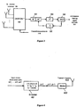
- Figure 1 illustrates wireless wideband transmission from multiple base stations to mobile receivers.
- Figure 2 is a block diagram of one embodiment of an encoder for encoding of information-bearing signal at one of the transmitting base stations.
- Figure 3 is a block diagram of one embodiment of a receiver structure at a mobile receiver for use with the encoder of Figure 2 .
- Figure 4 illustrates OSTBC-based encoding at one antenna at one embodiment of a base station.
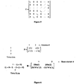
- Figure 5 illustrates a structure of a matrix V shown in Table 1.
- Figure 6 illustrates an example of code construction for use with a two-transmit base station system with a single transmit antenna per base-station using an Alamouti code as the baseline code.
- Figure 7 is a block diagram of one embodiment of an OSTFDM encoder at a base station.
- Figures 8A and 8B illustrate OSTFDM encoders at two base stations.
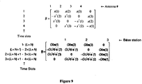
- Figure 9 illustrates an example of code construction for a four transmit base-station system in which each base station employs a single transmit antenna.
- Figure 10 is a block diagram of one embodiment of a OSTFDM receiver front end.
- Figure 11 is a block diagram of one embodiment of a computer system.
- One embodiment of the present invention relates, in general, to signal design and to managing sending/receiving information over wireless systems, with multiple transmit antennas and, potentially, multiple receive antennas.
- a mobile receives a signal (by use of one or several antennas) that is sent over multiple transmit antennas, and the transmit antennas are distributed over multiple base stations (i.e., they are not collocated).
- wideband transmission is achieved by using an outer binary convolutional code, bit-interleaved coded modulation, and an inner space-time block code that performs OFDM-type transmission.
- flexible unequal error protection for media signals is used in conjunction with these embodiments by using a rate-compatible punctured convolutional code as the outer code.
- Embodiments of the present invention are directed to the forward link, i.e., the base station-to-mobile transmission direction of transmission.
- Methods and apparatuses are disclosed for reliably transmitting an information-bearing stream of symbols from multiple base stations to one or more designated mobile receivers, where the desired objective of reliable transmission is obtained by space-time coding the information-bearing signal across all transmitting base stations (via a set of transmit antennas that are non-collocated).
- wideband (high data rate) transmission over frequency selective fading channels is used.
- the space-time codes are robust and flexible to changes in the number of transmit and receive antennas as well as the modem constellations. They also allow reliable data decoding at any mobile, even in the case that the signals transmitted by distinct base stations are received at the mobile asynchronously, i.e., relatively delayed with respect to one another. Compared to other existing schemes, proposed schemes allow for lower complexity receivers at the price of reduced symbol-rate. Also, in one embodiment, the techniques described herein provide flexible unequal error protection.
- the present invention relates to apparatus for performing the operations herein.
- This apparatus may be specially constructed for the required purposes, or it may comprise a general purpose computer selectively activated or reconfigured by a computer program stored in the computer.
- a computer program may be stored in a computer readable storage medium, such as, but is not limited to, any type of disk including floppy disks, optical disks, CD-ROMs, and magnetic-optical disks, read-only memories (ROMs), random access memories (RAMs), EPROMs, EEPROMs, magnetic or optical cards, or any type of media suitable for storing electronic instructions, and each coupled to a computer system bus.
- a machine-readable medium includes any mechanism for storing or transmitting information in a form readable by a machine (e.g., a computer).
- a machine-readable medium includes read only memory ("ROM”); random access memory (“RAM”); magnetic disk storage media; optical storage media; flash memory devices; electrical, optical, acoustical or other form of propagated signals (e.g., carrier waves, infrared signals, digital signals, etc.); etc.
- a class of space-time block codes operates in a system with N t transmit antennas distributed over multiple base stations.
- One advantage of the proposed methods is that they provide high-reliability information delivery at acceptable decoding complexity.
- advantages of the disclosed techniques include the following: 1) provide full "transmit base-station" diversity, for any set of relative delays between transmitting base stations, provided that none of the relative delays of arrival exceed the maximum allowable value (design parameter); 2) allow harvesting frequency diversity by means of the bit-interleaved coded modulation outer code; 3) do not require that the transmitting base-stations know the relative delays of arrivals of signals transmitted by different base stations; 4) complexity of the near-optimal receiver associated with these schemes does not grow with the number of total transmit antennas (over all base stations) used in the transmission, unlike other existing designs (where receiver complexity grows exponentially with the number of transmit antennas employed by the system); 5) iterative decoding yields improved performance at acceptable decoding complexity and provides improvements in performance, even in the case of communication over flat (frequency nonselective) fading wireless channels.
- Embodiments of the invention exploit intelligent wideband transmission of the information bearing signal over the multiple independently fading paths from each transmitting base station to a receiver in such a way that it provides full transmit base station diversity, the frequency diversity available in the transmission bandwidth, receive antenna diversity if multiple receive antennas are employed, and extended coverage.
- the information bearing signal is available at multiple base stations, and a single active base station with multiple transmit antennas is used.
- space-time block codes STBCs are used to provide diversity in the forward link, in the case that a single base station with multiple transmit antennas is employed for transmission by using an OFDM-based BICM system.
- a proposed technique possesses distinct connections to as well as differences from the other existing space-time coding designs.
- the connections are evident when one views each of the "active" base stations as an element in a virtual transmit antenna array, and suggest exploiting standard space-time coding techniques for providing diversity in these settings by treating each active base station antenna as a transmit antenna.
- each active base station must encode its data independently.
- One important consequence of this is that, in general, there can be a lack of time-synchronization between the transmissions from different base stations to the receiver.
- This asynchrony can arise due to the fact that the individual base stations may be operating independently, but also due to the fact that even if the signals the signals transmitted from spatially dispersed base stations to a receiver are transmitted synchronously, they may arrive asynchronously at the receiver. Furthermore, in the context of wideband transmission, the system allows low complexity receiver designs that can harvest not only the available transmit antenna diversity but also the available frequency diversity.
- the underlying basis of the transmission consists of exploiting an outer-inner code construction in which the inner code harvests in full the available transmit base station diversity while the outer code harvest the available frequency diversity.
- the techniques described herein include the use of a class of space-time coding and associated transceivers for enabling reliable transmission of common information from a set of base stations to one or more receivers over wideband wireless channels.
- the setting of interest for the proposed embodiments is depicted in Figure 1 , which is described below.
- Embodiments of the invention are focused on the forward link (FL, base-to-mobile).
- FL forward link
- the signal is transmitted over a number of transmit antennas distributed over multiple base stations.
- transceivers achieve reliable transmission of a common information signal by sending distinct encodings from each antenna at each base station without the need for synchronizing the transmissions.
- a proposed method results in reduced decoding-complexity schemes that provide full "transmit base-station” diversity, frequency diversity, and receiver antenna diversity (if multiple receive antennas are employed) for arbitrary sets of relative delays in the reception of the signals transmitted from different base stations, and provided that the maximum relative delay between transmissions does not exceed an a priori determined value.
- Embodiments of the invention include transceivers for asynchronous reliable wideband wireless communication of a symbol stream from N t transmitting antennas distributed over multiple base stations to one or more receivers.
- Figure 1 illustrates an asynchronous wireless wideband transmission from multiple base stations to mobile receivers (terminals).
- multiple base stations 102 1- n are shown, and each of these base stations has, potentially, multiple antennas for communicating with mobile receivers, such as mobile receiver 103.
- Each transmitting base station of base stations 102 1- n has available the same information-bearing symbol stream that is to be communicated to the receiver(s) 103.
- communication between the base stations and mobile receivers occurs using transmission techniques that employ the following building blocks:
- Central control unit 101 is communicably coupled to base stations 102 1- n to control base stations 102 1- n .
- control unit 101 manages the information flow (signals) to and from the involved base stations/transmit antennas as well as channel identification algorithms.
- Control unit 101 selects the transmit antennas and base stations from a collection of available base stations.
- control unit 101 communicates with the (transmitting) base stations 102 1- n via wire (or wireless broadcast). It should be noted that the signals transmitted from any two antennas (whether the antennas reside on the same or on different base stations) are typically not the same, just as is the case with existing space time code designs for systems with collocated transmit antennas.
- Figure 2 is a block diagram of one embodiment of an encoder for encoding of information-bearing signal at one of the transmitting base stations.
- an encoder for encoding of information-bearing signal at one of the transmitting base stations.
- such an encoder is used for encoding and transmission at a base station.
- the information-bearing signal 201 is first encoded by a binary code.
- the binary code may be, for example, a block code, an LDPC code, a convolutional code, or a turbo code.
- the information bearing signal is first encoded by a rate-compatible punctured convolutional code (RCPC) 202, followed by a bit interleaver 203, followed by a mapper/ modulator unit 204.
- the output of mapper/modulator 204 is then converted into vector parallel streams by serial-to-parallel (S/P) converter 205 that are encoded according to the OFDM-based orthogonal space-time block code system 206.
- S/P serial-to-parallel
- the output streams from OSTFDM 206 are then passed through a controller 204 that selects which output stream of the inner space-time block code is transmitted over any one of transmit antennas 208.
- the outer code and the interleaver in the BICM scheme provide additional robustness (to that provided by the OSTBC) in the transmission, yielding reliable, high data-rate, wideband transmission over frequency selective channels.
- N t and N r denote the number of transmit and receive antennas, respectively, while N denotes the number of OFDM frequency components.
- An orthogonal space-time block code is employed after the BICM scheme.
- the OFDM-based OSTBC is described in U.S. Provisional Patent Application No. 60/857,265 , entitled “A Method and Apparatus for Asynchronous Space-Time Coded Transmission from Multiple Base Stations over Wireless Radio Networks," filed November 8, 2006 and is referred to as an orthogonal space-time frequency division multiplexing (and labeled OSTFDM).
- an orthogonal space-time frequency division multiplexing and labeled OSTFDM.
- the OSTBC handles signals received from different transmitter antennas which are arriving at the receiver asynchronously.
- the reason for this is that it is assumed that the transmitter antennas are distributed over multiple base stations (i.e., they are not collocated).
- the receiver is robust to time delays between signals from different transmitter antennas.
- the inner code employed in the encoder/transmitter shown in Figure 2 is referred to herein as an orthogonal space-time frequency division multiplexing (OSTFDM) code.
- the OSTFDM code is an OFDM-type OSTBC constructed according to method described in U.S. Provisional Patent Application No. 60/857,265 , entitled “A Method and Apparatus for Asynchronous Space-Time Coded Transmission from Multiple Base Stations over Wireless Radio Networks," filed November 8, 2006.
- the N t transmit-antenna OSTFDM (referred to as induced code) is generated via systematic transformations of a conventional N t transmit transmit-antenna orthogonal space-time block code, referred to herein as the "baseline" code.
- the baseline OSTBC is a k -by- t -by- N t code, i.e., it is an OSTBC that encodes k information symbols at a time into a block of t time slots, over N t (collocated) antennas. Letting x (1), x (2), ...
- the baseline encoder denotes a typical block of k scalar, complex-valued information-bearing symbols that are inputs to the baseline OSTBC
- the baseline encoder generates a code that is represented by a matrix B of dimensions t by N t whereby the ( j,i )th element of B denotes the sample that is to be transmitted by the antenna i at time j , in the context of an n transmit-antenna system utilizing the baseline code.
- a K -by- T -by- N t induced OSTBC is generated, which encodes K information symbols at a time over a block of T time slots, and over n single-antenna transmit base-stations.
- the values of the integers K and T are determined as follows.
- the integer K equals N times k , signifying that, for each scalar symbol encoded by the baseline code, the induced code encodes a vector of N symbols.
- the induced code encodes K symbols at a time into blocks of T samples/per transmit base-station, where T equals t ( N+L ) (i.e., t times the sum of N and L ), and where L is chosen so as to satisfy the maximum allowable relative delay constraint.
- the receiver used at the mobile receiver comprises a linear front-end for the orthogonal non-binary space-time block code resulting in symbol-by-symbol modem demapper decisions, a deinterleaver and a maximum a posteriori probability decoder for the outer convolutional code.
- iterative decoding is performed by using the demapper as the inner MAP decoder.
- Non-iterative receivers that are based on the Viterbi algorithm correspond to reduced-complexity options and may also be used.
- FIG 3 is a block diagram of one embodiment of a receiver structure at a mobile receiver for use with the encoder of Figure 2 .
- the receiver comprises a linear front end for the inner code, followed by a decoder for the outer code system.
- a linear receiver front-end 302 is employed by exploiting channel estimates and relative delay of arrival estimates for each transmit-antenna to receive-antenna channel.
- the output of the linear front end 302 is a single baud-rate sequence that is demodulated demapped and deinterleaved demodulator/demapper unit 303, the output of demodulator/demapper 303 is input to bit deinterleaver 304.
- Bit deinterleaver 304 performs bit deinterleaving.
- the output of bit deinterleaver 304 are sent to the Maximum a Posteriori (MAP) decoder 306, which obtains an estimate of the information-bearing signal 307.
- MAP Maximum a Posteriori
- New MAP estimates are obtained iteratively by using as inputs to the demapper re-interleaved versions of the current MAP estimates created by bit interleaver 305, which are sent to demodulator/demapper 303.
- Figure 4 illustrates OSTBC-based encoding at one antenna in one embodiment of a base station. It is assumed that the given antenna's index in the enumeration of all transmitting antennas over all transmitting base stations equals i , where i is an integer between 1 and N t . That is, i is the index of the given antenna in enumeration of all transmit antennas over all base stations.
- s (1), s(2), ..., s ( k ) denote a typical block of k information-bearing symbol input vectors of dimension N that are inputs to the induced OSTBC according to one embodiment of the present invention.
- the i -th vector s ( i ) is a vector (or block) of N scalar complex-valued, information-bearing symbols in the induced code (where N denotes the blocking factor in the construction).
- induced encoder 401 Given such a set of input vectors, induced encoder 401 generates an induced code that is represented by a matrix B with T rows and n columns, where T equals t times the sum of N and L .
- the ( j , i )th element of B denotes the sample that is to be transmitted by the i -th base station at time j , in the context of an n transmit base-station system utilizing the induced code (where the output of an OFDM transmitter is expressed as a "single-carrier" type output whereby the symbol transmitted at time j is the symbol that will be modulated on the pulse-shaping waveform at time j.) Note that the combined effect of a block of consecutive N+L transmissions is an N-tone OFDM symbol with circular prefix of length L.
- the induced orthogonal space-time block code B is generated by systematic transformations of the elements of the associated baseline code B . More specifically, in one embodiment, each entry of the baseline OSTBC equals one of the following: (i) the value zero; (ii) one of the k input symbols; (iii) one of the k input symbols negated; (iv) the complex conjugate of an input symbol; (v) the negative of the complex conjugate of an input symbol. Therefore, to generate the induced OSTBC, initially the mth vector input to B , s ( m ), is paired with the mth scalar input to B (i.e., x(m)).
- B is generated from B by replacing each entry of B with a vector of dimension N + L according to the rules specified in Table 1 below:
- Table 1 above illustrates systematic construction of the induced OSTBC from a baseline OSTBC.
- each information-bearing symbol x(m) in the baseline OSTBC matrix B is associated with a vector of information bearing symbols s(m), of dimension N, in the induced code B .
- each scalar entry of the original OSTBC matrix B is replaced by a vector entry of dimension N+L, according to the table above.
- the matrix ⁇ is a DFT matrix with N rows and N columns.
- the matrix G has N+L rows and N columns.
- the transformation process takes as an input a vector of dimension N and produces a vector of dimension N+L, in which the last N entries of the output vector are the entries of the input vector (in the same order) and in which the L first entries of the output vector are the last L entries of the input vector (in the same order).
- the superscripts " * " and " H denote element-wise conjugation and the Hermitian (conjugate transpose) operation, respectively. For more information on these operations, see R. A. Horn and C. R. Johnson, Matrix Analysis. New York: Cambridge Univ. Press, 1994 .
- matrix ⁇ is a (normalized) DFT matrix of N rows and N columns.
- this entry is replaced by a vector v ( m ), of dimension N + L generated by: 1) generating the intermediate vector z ( m ), of dimension N , by multiplying the vector s ( m ) with the matrix F ; 2) adding an L -sample circular prefix to z ( m ) to produce a vector v ( m ) (i.e., generating a vector v ( m ) of dimension N + L where the first L entries of v ( m ) are the last L entries of z ( m ) and the last N entries of v ( m ) are the entries of z (m) (in the same order)); and 3) replacing the ( i,j )th entry of B (equal to x ( m ) by assumption) with v ( m ).
- this entry is replaced by a vector u ( m ), of dimension N + L generated by: 1) generating an intermediate vector z ( m ), of dimension N , by multiplying the element-wise complex conjugate of the vector s ( m ) with the matrix F * , which is the element-wise complex conjugate of the matrix F ; 2) generating an intermediate vector d ( m ), of dimension N , by multiplying the vector z ( m ) with a matrix U *, which is the element-wise complex conjugate of the matrix U ; 3) adding an L -sample circular prefix to d (m) to produce a vector u( m ), i.e., generate a vector u ( m ) of dimension N + L where the first L entries of u ( m m
- Figure 6 shows a special case of generating a code to be used with a two-transmit base station system, where each base station has a single transmit antenna per base-station using the Alamouti code as the baseline code.
- the baseline Alamouti code (labeled B ) encodes 2 symbols at a time over two samples per antenna at a rate of 1 symbol/channel use, and the associated induced OSTBC, B , encodes 2-times- N symbols at a time over 2-times- ( N + L ) samples/per base-station, at a rate N /( N + L ) symbols/channel use.
- the Alamouti code (depicted via the matrix B in Figure 6 ) codes two symbols, x (1) and x (2), over two time slots and two antennas.
- the first antenna transmits the complex conjugate of x (2)
- the second antenna transmits the negative of the complex conjugate of x (1).
- the induced code is shown with the matrix B in Figure 6 .
- the samples transmitted by the first antenna at times L + N +1 through 2 ⁇ ( L + N ) are generated as follows: (i) apply transformation U on the DFT of s(2); and (ii) prepend the resulting vector of dimension N with its L -sample circular prefix.
- the samples transmitted by the second antenna at times L + N +1 through 2 ⁇ ( L + N ) are similarly constructed according to B .
- FIG. 7 is a block diagram of one embodiment of an OFDM-based OSTBC encoder used by one of base stations 702 1- n for encoding for transmission on a typical antenna element.
- the encoder takes as input the information-bearing symbols, or samples generated by an outer code in the system. Encoding is performed in blocks of size K , where K equals k times N .
- Serial-to-parallel converter 701 splits each block of K symbols into k sub-blocks, information symbol vectors s (1), s (2), ..., s ( k ), each of which has N symbols.
- the processed blocks are then reordered (and zero blocks are inserted where appropriate), and each block is then individually processed as shown in Figure 7 , with the position of switches 720 1- k , 721 1- k , 722 1- k , and 723 1- k and the reordering operation set according to the OSTBC column associated with the given antenna element.
- the encoder applies an N -pt IDFT to k sub-block s(1).
- the encoder projects a matrix U 703 1 onto the transformed data.
- matrix U 703 1 is a time reversal matrix.
- the encoder performs an element-wise complex conjugate 704 1 to the results of projecting the transformed data onto matrix U 703 1 .
- Switch 721 1 is set to the same path (lower or upper) as switch 720 1 .
- the results from the selected (upper or lower) path are then directed through, either the upper path of switch 722 1 (and the upper path of 723 1 , which is always set to the same path as switch 722 1 ) to circular prefix unit 706 1 , or through the lower path of switch 722 1 to "negate" block 705 1 and through the lower path of switch 723 1 to circular prefix unit 706 1 .
- the remainder of the information symbol vectors s(2), ..., s ( k ) are processed in the similar fashion.
- Circular prefix units 706 1- k insert an L-sample circular prefix to create an N + L sized processed block.
- the position of switches in Figure 7 and the reordering operation are dictated by the column of the OFDM-based OSTBC that is associated with the given antenna element.
- the T -sample vector generated by the reordering/zero insertion operation is passed through parallel-to-serial converter 708 to a modem 709, which performs pulse-shaping, amplification, and modulation to radio-frequency (RF) in a manner well-known in the art. Afterwards, modem 709 sends the data for transmission over antenna element 710.
- RF radio-frequency
- Figure 9 demonstrates another example of code constructing an OSTFDM code from an existing baseline code for a four transmit base-station system in which each base station employs a single transmit antenna.
- Figure 9 shows the special case of generating a code to be used with a four transmit-base-station system.
- Figure 9 shows the baseline OSTBC, B , which encodes 3 symbols over four samples per antenna at a rate of 3 ⁇ 4 symbols/channel use, and the associated induced OSTBC, B , which encodes 3-times-N symbols at a time over 4-times-( N + L ) samples/per base-station, at a rate 3 ⁇ 4 times N/( N + L ) symbols/channel use.
- This code also provides a systematic induced OSTBC for a three transmit-base-station system (e.g., by dropping one of the columns of B ).
- the code can also be used in the context of a two-base station system whereby each base station has two transmit antennas. In this case columns 1-2 of B are associated with the two transmit antennas at the one of the base stations and columns 3-4 are associated with the two transmit antennas at the other base station.
- Figures 8A and 8B are block diagrams of one embodiment of encoders at respective base stations that implement an OSFDM coder.
- the encoders in Figures 8A and 8B support an OFDM-based OSTBC implementation in each base station in a scheme involving transmission from two base stations, each with a single antenna element for transmission.
- the system takes as input blocks of N (complex-valued scalar) symbols generated by the outer code in the system.
- the encoder includes serial-to parallel converter 801 that receives a set of information symbol vectors s(1) and s(2) of dimension " N " and converts them into parallel form.
- N -point IDFT 802 transforms the information symbol vector s(1) into N symbols.
- Circular prefix unit 803 adds a prefix of L bits to the N symbols, thereby creating an N + L set of data that is sent to parallel-to serial-converter 808, where it is converted to a serial steam.
- N -point IDFT 804 transforms the information symbol vector s(2) into N symbols. Then projection unit 805 projects the matrix output from N -point IDFT transform 804 onto matrix U .
- matrix U is a time-reversal matrix.
- Conjugate unit 806 performs the conjugate operation on the output of projection unit 805.
- Circular prefix unit 807 adds a prefix of L symbols onto the conjugated output of conjugate unit 806.
- the output of circular prefix unit 807 is input to parallel-to-serial converter 808, which converts data on its parallel inputs into serial form.
- the output of parallel-to-serial converter 808 is sent to modem 809, which causes the data to be transmitted via antenna 810.
- the encoder at the second base station is described.
- the encoder includes serial-to parallel converter 811 that receives a set of information symbol vectors of dimension " N " and converts them into parallel form.
- N -point IDFT 812 transforms the information symbol vector s(2) into N symbols.
- Circular prefix unit 813 adds a prefix of L bits to the N symbols, thereby creating an N+L set of data that is sent to parallel-to serial-converter 818, where it is converted to a serial steam.
- N -point IDFT 814 transforms the information symbol vector s (1) into N symbols. Then projection unit 815 projects the matrix output from N -point IDFT transform 814 onto matrix U .
- matrix U is a time-reversal matrix.
- Conjugate unit 816 performs the conjugate operation on the output of projection unit 815.
- Circular prefix unit 817 adds a prefix of L symbols onto the conjugated output of conjugate unit 816.
- the output of circular prefix unit 817 is input to parallel-to-serial converter 818, which converts data on its parallel inputs into serial form.
- the output of parallel-to-serial converter 818 is sent to modem 819, which causes the data to be transmitted via antenna 820.
- Figure 10 is a block diagram of one embodiment of an OFDM-based linear receiver front-end structure. More specifically, the receiver front end generates soft estimates of the input symbols to the inner code. These estimates are then used as inputs to the demodulator/demapper block.
- the front-end structure performs a symbol detection algorithm and produces a scalar sequence that is used by the outer decoder for symbol decisions.
- This algorithm can be readily applied for detection of the information bearing vectors s (1), s (2), ..., s ( k ), in the case of data transmission over slowly varying flat fading channels, but can also be applied for symbol detection over slowly-time varying frequency selective channels.
- the channel is varying slowly enough so that accurate estimates of the channel fading coefficients can be obtained (via the pilot estimation phase) and that the receiver employs a standard front-end which consists of a linear filter (e.g., a square-root raised cosine pulse matched to the transmitter pulse-shaping filter) followed by a baud-rate sampler (with adjustable sampling times).
- a linear filter e.g., a square-root raised cosine pulse matched to the transmitter pulse-shaping filter
- baud-rate sampler with adjustable sampling times.
- the receiver has available a sequence of samples that is a linear superposition of the responses of all transmitted OSTBC sequences in background noise.
- the effective impulse response of a channel from a transmitting base station to a receiver is at most equal to L ⁇ samples long.
- the constant L ⁇ is determined by the "effective" duration (in symbol periods) of the response of the pulse-shaping waveform (used at each encoder) through the receiver front-end filter.
- the value of L ⁇ depends on the roll-off factor employed and is typically between four and six.
- the first nonzero samples in the impulse responses of any two such channel responses are at most L o samples apart (due to the assumed L o maximum relative delay constraint).
- estimates of the relative delays in the transmissions are first obtained, together with estimates of the channel fading coefficients.
- the receiver of Figure 10 performs the following operations. Given the relative delay estimates, the block-symbol timing reference is determined and the received sampled sequence is partitioned into blocks of length T . In one embodiment, these operations are performed at the receiver: they are part of the timing-recovery and synchronization operations.
- the relative delays are first estimated. For this, the transmitting antennas transmit space-time coded sequences generated via pilot signals, which are known to the receiver.
- the receiver has an analog linear front-end (front-end filtering, demodulation, and sampling) and uses the knowledge of the transmitted signal in order to estimate and readjust its sampling times, which is an operation that is part of timing-recovery. In the asynchronous case, multiple relative delays are estimated, one for each transmit antenna.
- the blocking into r vectors is dictated by determining the beginning of any block as the beginning of the transmitted signal that is arriving first. These relative timing delays change slowly with time, so they can be estimated through a standard pilot-assisted channel estimation phase, used to estimate the channel fading coefficients. This processing is performed on a block-by-block basis.
- the variable r represents the received vector of concentric samples of dimension T that is associated with the current block of data.
- prefix removal unit 1002 constructs a vector y ( m ) of dimension N , as the last N entries of the vector r ( m ), by removing the prefix data.
- the ith entry of y (m) equals the "L+I"th entry of r (m).
- Y HS + W
- S denotes the real-valued vector of dimension 2 K (i.e., 2 times K ) that equals the concatenation of the (element-wise) real part of s
- H denotes a real-valued matrix with 2N t (i.e., 2 times N times t) rows and 2 K (i.e., 2 times K ) columns, which can be readily constructed at the receiver, given knowledge of the fading channel coefficients, relative delays, and the induced code structure
- Conversion unit 1009 converts x into a sequence of K scalars. This is achieved by extracting the K scalar components out of the vector x (which has dimension K ).
- the output of conversion unit 1009 is an input to the demodulator/demapper.
- the estimates of the relative delays at the receiver are used to adjust the sampling timing of the baud-rate sampler at the receiver front-end.
- Such adjustments can have significant benefits from a receiver performance point of view. For instance, consider the case where a two base-station system is employed and where the relative delay between the received signals equals "half" a symbol period.
- the receiver performance is improved, and potentially optimized, when the baud-rate sampler is a quarter-sample "behind” one of the transmission and a quarter-sample “ahead” of the other, and takes its worse value when the baud-rate sampler is in-sync with one of the transmissions and half-a-sample out of sync with the other.
- the baud-rate sequence of samples (that is partitioned into r -type vectors of the form shown in Figure 10 ) is generated by passing the (down converted continuous-time) received signal through the following cascade of systems that includes: a linear front-end filter (e.g., a square-root raised cosine filter); an oversample-by- M system where M is an integer greater than 1 (this system keeps M samples per symbol period); a discrete-time delay-by- n o -samples system (the output of this system is its input delayed by n o -samples); and a decimate-by- M system (this system generates an output by discarding all by every M th sample of the input sequence).
- the estimates of the relative sampling times (available at the receiver via the pilot phase) can be employed to adjust the (integer) delay parameter no in the delay-by-n o system prior to the decimator in order to optimize the decoder performance.
- the baud-rate sequence of samples (that is partitioned into r-type vectors) by passing the (down converted continuous-time) received signal through the following cascade of systems, which include
- the estimates of the relative sampling times can be employed to optimally adjust the (integer) delay parameter no in the delay-by-n o system prior to the decimator in order to optimize the decoder performance.
- SISO 1 soft in, soft out
- SISO 2 decoder for the outer convolutional code should ideally be a MAP (BCJR) or a maxlog MAP decoder. Note that with the outer code and interleaver some frequency diversity is obtained when communicating over frequency selective channels, since the interleaving and coding takes place also in the frequency domain as well as in the time domain.
- the receiver in these schemes is relatively simple because of the inner orthogonal space-time block code that is employed (labeled OSTFDM).
- the demapper SISO 1 in this case only grows exponentially with the number of bits in the constellations but not with the number of transmit antennas.
- a sub-optimum receiver could be a demapper followed by a Viterbi decoder (instead of a MAP decoder and no iterative decoding. It has worse performance than the iterative decoding (ID) algorithm but it has lower decoding complexity.
- space-time coded transmission via a set of transmitter antennas distributed over multiple (non-collocated) base stations, extended coverage and reliability can be achieved.
- the space-time codes using an inner STBC based on OFDM are robust to asynchronous component signals.
- the proposed design attains the desired performance benefits by employing a low complexity receiver at each intended mobile receiver.
- the use of an outer binary convolutional code and bit interleaving makes efficient and robust systems for wideband transmission. Additional frequency diversity is typically obtained and iterative decoding can be employed with the demapper as the inner decoder and the outer decoder being MAP decoder for the RCPC code. (Even in the case of communication over flat fading channels, the iterative decoding structure can provide performance benefits).
- the use of an RCPC code as the outer binary convolutional code yields flexible UEP properties. The entire system is quite flexible and robust to changes in the number of transmit and receive antennas as well as modem constellations.
- FIG 11 is a block diagram of an exemplary computer system that may perform one or more of the operations described herein.
- computer system 1100 may comprise an exemplary client or server computer system.
- Computer system 1100 comprises a communication mechanism or bus 1111 for communicating information, and a processor 1112 coupled with bus 1111 for processing information.
- Processor 1112 includes a microprocessor, but is not limited to a microprocessor, such as, for example, PentiumTM, PowerPCTM, AlphaTM, etc.
- System 1100 further comprises a random access memory (RAM), or other dynamic storage device 1104 (referred to as main memory) coupled to bus 1111 for storing information and instructions to be executed by processor 1112.
- main memory 1104 also may be used for storing temporary variables or other intermediate information during execution of instructions by processor 1112.
- Computer system 1100 also comprises a read only memory (ROM) and/or other static storage device 1106 coupled to bus 1111 for storing static information and instructions for processor 1112, and a data storage device 1107, such as a magnetic disk or optical disk and its corresponding disk drive. Data storage device 1107 is coupled to bus 1111 for storing information and instructions.
- ROM read only memory
- data storage device 1107 such as a magnetic disk or optical disk and its corresponding disk drive.
- Data storage device 1107 is coupled to bus 1111 for storing information and instructions.
- Computer system 1100 may further be coupled to a display device 1121, such as a cathode ray tube (CRT) or liquid crystal display (LCD), coupled to bus 1111 for displaying information to a computer user.
- a display device 1121 such as a cathode ray tube (CRT) or liquid crystal display (LCD)
- An alphanumeric input device 1122 may also be coupled to bus 1111 for communicating information and command selections to processor 1112.
- cursor control 1123 such as a mouse, trackball, trackpad, stylus, or cursor direction keys, coupled to bus 1111 for communicating direction information and command selections to processor 1112, and for controlling cursor movement on display 1121.
- bus 1111 Another device that may be coupled to bus 1111 is hard copy device 1124, which may be used for marking information on a medium such as paper, film, or similar types of media.
- hard copy device 1124 Another device that may be coupled to bus 1111 is a wired/wireless communication capability 1125 to communication to a phone or handheld palm device.
Landscapes
- Engineering & Computer Science (AREA)
- Computer Networks & Wireless Communication (AREA)
- Signal Processing (AREA)
- Radio Transmission System (AREA)
- Mobile Radio Communication Systems (AREA)
Claims (8)
- Un système de communication sans fil comprenant :un ou plusieurs terminaux (103), etau moins deux stations de base (102), chacune comprenant un codeur (401), destinées à communiquer de manière non filaire des signaux porteurs d'informations (201, 307) à partir d'un ensemble d'éléments d'antenne (208, 403, 710, 810, 820) répartis sur plusieurs stations de base non co-implantées vers les un ou plusieurs terminaux, de sorte qu'au moins un élément d'antenne de l'ensemble d'éléments d'antenne soit implanté sur chaque station de base,où le codeur sur chacune des au moins deux stations de base comprend une concaténation d'une modulation codée à code binaire extérieur et à bits entrelacés, et caractérisé en ce que le codeur comprend en outre un code à blocs espace-temps de type OFDM induit destiné à coder l'un des signaux porteurs d'informations,où le code à blocs espace-temps est créé à partir d'un code de ligne de base, etoù toutes les antennes émettrices de toutes les stations de base qui émettent sont énumérées et chaque antenne se voit attribuer une colonne du code induit.
- Le système selon la Revendication 1 où une station de base associée à chaque antenne émettrice génère un vecteur pour l'émission de chaque bloc de symboles porteurs d'informations selon une colonne correspondante du code induit à blocs espace-temps.
- Le système selon la Revendication 1 où au moins une des stations de base comprend un émetteur équipé de :une entrée destinée à recevoir des signaux porteurs d'informations,un codeur de code extérieur binaire (202) couplé à l'entrée de façon à coder le signal porteur d'informations et à générer un train binaire,un entrelaceur de bits (203) couplé au train binaire, et suivi par un mappeur (204) et un modem (204) destiné à exécuter une modulation codée à bits entrelacés sur le train binaire, etun codeur de code à blocs espace-temps orthogonal (OSTBC) intérieur de type OFDM (206) couplé au modem de façon à générer un ou plusieurs trains de données pour émission.
- Le système selon la Revendication 3 où le modem (204) et le codeur OSTBC (206) sont couplés par l'intermédiaire d'un convertisseur série à parallèle (205) qui est actionnable de façon à convertir des sorties de l'entrelaceur de bits (203) d'une forme série à parallèle.
- Le système selon la Revendication 3 où le codeur de code extérieur binaire comprend un codeur qui utilise un code sélectionné dans un groupe comprenant un code de convolution discontinu compatible avec le débit (RCPC), un code turbo et un code à blocs.
- Le système selon la Revendication 3 où le codeur OSTBC utilise le code à blocs espace-temps en tant que code induit, qui est dérivé d'un code à blocs espace-temps orthogonal, le code à blocs espace-temps orthogonal étant un code de ligne de base.
- Le système selon la Revendication 6 où le codeur OSTBC code un vecteur de bloc de plusieurs symboles, comprenant un code induit, pour tout symbole d'informations scalaires codé par le code de ligne de base.
- Le système selon la Revendication 1 où au moins une des stations de base comprend un récepteur équipé de :une extrémité avant linéaire (302) possédant un décodeur interne destiné à exécuter un décodage avec un code à blocs espace-temps orthogonal (OSTBC) intérieur de type OFDM de façon à générer des symboles,un décodeur extérieur possédant un démappeur de symboles interne (303) destiné à exécuter un démappage symbole par symbole de symboles vers des bits à partir de l'extrémité avant linéaire,un désentrelaceur de bits (304) destiné à exécuter un désentrelacement sur les symboles démappés reçus du démappeur de symboles interne, etun décodeur MAP externe (306).
Applications Claiming Priority (3)
| Application Number | Priority Date | Filing Date | Title |
|---|---|---|---|
| US86153906P | 2006-11-28 | 2006-11-28 | |
| US11/939,353 US8059732B2 (en) | 2006-11-28 | 2007-11-13 | Method and apparatus for wideband transmission from multiple non-collocated base stations over wireless radio networks |
| PCT/US2007/024572 WO2008066888A1 (fr) | 2006-11-28 | 2007-11-28 | Procédé et dispositif de transmission en large bande à partir de multiples stations de base espacées sur des réseaux radio sans fil |
Publications (2)
| Publication Number | Publication Date |
|---|---|
| EP2087613A1 EP2087613A1 (fr) | 2009-08-12 |
| EP2087613B1 true EP2087613B1 (fr) | 2012-04-18 |
Family
ID=39247135
Family Applications (1)
| Application Number | Title | Priority Date | Filing Date |
|---|---|---|---|
| EP07862325A Not-in-force EP2087613B1 (fr) | 2006-11-28 | 2007-11-28 | Procédé et dispositif de transmission en large bande à partir de multiples stations de base espacées sur des réseaux radio sans fil |
Country Status (6)
| Country | Link |
|---|---|
| US (1) | US8059732B2 (fr) |
| EP (1) | EP2087613B1 (fr) |
| JP (1) | JP5215318B2 (fr) |
| KR (1) | KR100977426B1 (fr) |
| AT (1) | ATE554537T1 (fr) |
| WO (1) | WO2008066888A1 (fr) |
Families Citing this family (21)
| Publication number | Priority date | Publication date | Assignee | Title |
|---|---|---|---|---|
| KR100728241B1 (ko) * | 2006-09-21 | 2007-06-13 | 한국전자통신연구원 | 시공간 블록 부호를 적용시킨 신호를 송신해 다이버시티이득을 얻기 위한 위성통신 시스템 및 그 단말기에서의수신 신호 처리 방법 |
| US8155232B2 (en) * | 2007-05-08 | 2012-04-10 | Samsung Electronics Co., Ltd. | Multiple antennas transmit diversity scheme |
| WO2009066208A2 (fr) * | 2007-11-20 | 2009-05-28 | Koninklijke Philips Electronics N.V. | Réseau de transmission de données |
| JP5260131B2 (ja) * | 2008-04-28 | 2013-08-14 | 株式会社エヌ・ティ・ティ・ドコモ | 基地局、移動局及び共通情報通信方法 |
| US8514693B2 (en) * | 2008-07-11 | 2013-08-20 | Alcatel Lucent | Broadcast and multicast in single frequency networks using othrogonal space-time codes |
| CN101651880B (zh) * | 2008-08-11 | 2013-12-25 | 株式会社Ntt都科摩 | 多小区协作发送方法 |
| TW201012108A (en) * | 2008-08-18 | 2010-03-16 | Agency Science Tech & Res | Analog space-time relay method and apparatus for a wireless communication relay channel |
| WO2010030213A1 (fr) | 2008-09-12 | 2010-03-18 | Telefonaktiebolaget L M Ericsson (Publ) | Procédés et dispositifs de codage spatial |
| CN101729215B (zh) * | 2008-10-28 | 2013-10-02 | 华为技术有限公司 | 空时/空频码构造方法、发射方法及装置 |
| US8385904B2 (en) * | 2008-11-18 | 2013-02-26 | At&T Intellectual Property Ii, L.P. | Space time coding where space diversity derives from use of multiple base stations |
| US9577608B2 (en) * | 2009-08-14 | 2017-02-21 | Qualcomm Incorporated | Discrete time lowpass filter |
| US8396420B2 (en) * | 2009-12-30 | 2013-03-12 | Ubidyne, Inc. | Active antenna system for a mobile communications network as well as a method for relaying a plurality of radio signals through the active antenna system |
| FR2955221A1 (fr) * | 2010-01-13 | 2011-07-15 | France Telecom | Procede de transmission d'un signal numerique pour un systeme distribue, produit programme et dispositif relais correspondants |
| DE102010032218A1 (de) * | 2010-07-26 | 2012-01-26 | Siemens Aktiengesellschaft | Verfahren zur paketvermittelten Datenübertragung, insbesondere zwischen einem Transportmittel und einer mit dem Transportmittel kommunizierenden Infrastruktur |
| US8599794B2 (en) * | 2010-09-08 | 2013-12-03 | Intel Corporation | Enhanced base station and method for communicating through an enhanced distributed antenna system (eDAS) |
| JP5760920B2 (ja) * | 2011-09-30 | 2015-08-12 | 富士通株式会社 | 符号化信号の繰り返し復号法及び符号化信号の繰り返し復号装置 |
| US20150058704A1 (en) * | 2013-08-23 | 2015-02-26 | Sirius Xm Radio Inc. | Parameterized interleaver for a multi-rate system |
| US9762360B2 (en) * | 2014-06-09 | 2017-09-12 | Allen LeRoy Limberg | Digital television broadcasting system using coded orthogonal frequency-division modulation with multilevel low-density-parity-check coding |
| US10433187B2 (en) * | 2015-04-17 | 2019-10-01 | Huawei Technologies Canada Co., Ltd. | System and method for utilizing multidimensional constellations |
| US10257105B2 (en) * | 2016-12-02 | 2019-04-09 | At&T Intellectual Property I, L.P. | Facilitation of physical layer design for 5G networks or other next generation networks |
| US10211953B2 (en) * | 2017-02-07 | 2019-02-19 | Qualcomm Incorporated | Antenna diversity schemes |
Family Cites Families (72)
| Publication number | Priority date | Publication date | Assignee | Title |
|---|---|---|---|---|
| US5737691A (en) | 1995-07-14 | 1998-04-07 | Motorola, Inc. | System and method for allocating frequency channels in a two-way messaging network |
| GB2304495B (en) | 1995-08-15 | 1999-12-29 | Nokia Mobile Phones Ltd | Radio resource sharing |
| US5982327A (en) | 1998-01-12 | 1999-11-09 | Motorola, Inc. | Adaptive array method, device, base station and subscriber unit |
| DE69923970T2 (de) | 1999-09-14 | 2006-04-27 | Lucent Technologies Inc. | Kanaldecodiereinrichtung und Verfahren zum Kanaldecodieren |
| US7072295B1 (en) * | 1999-09-15 | 2006-07-04 | Tellabs Operations, Inc. | Allocating network bandwidth |
| US6597743B1 (en) | 1999-12-07 | 2003-07-22 | Ericsson Inc. | Reduced search symbol estimation algorithm |
| US7441045B2 (en) * | 1999-12-13 | 2008-10-21 | F5 Networks, Inc. | Method and system for balancing load distribution on a wide area network |
| US6804307B1 (en) | 2000-01-27 | 2004-10-12 | Telefonaktiebolaget Lm Ericsson (Publ) | Method and apparatus for efficient transmit diversity using complex space-time block codes |
| US7436895B1 (en) | 2000-03-01 | 2008-10-14 | Spyder Navigations L.L.C. | Concatenated space-time coding |
| JP2001352258A (ja) | 2000-06-08 | 2001-12-21 | Sony Corp | 復号装置及び復号方法 |
| JP2002009692A (ja) * | 2000-06-23 | 2002-01-11 | Matsushita Electric Ind Co Ltd | データ伝送装置及びデータ伝送方法 |
| EP1204283A1 (fr) | 2000-11-06 | 2002-05-08 | Telefonaktiebolaget L M Ericsson (Publ) | Réseau cellulaire radio avec réutilisation des fréquences |
| US7023840B2 (en) * | 2001-02-17 | 2006-04-04 | Alcatel | Multiserver scheduling system and method for a fast switching element |
| CN100365965C (zh) | 2001-05-08 | 2008-01-30 | 西门子公司 | 在具有并行级联编码及调制的多载波系统中传输数据的方法和装置 |
| US7243295B2 (en) | 2001-06-12 | 2007-07-10 | Intel Corporation | Low complexity channel decoders |
| JP4719932B2 (ja) * | 2001-07-10 | 2011-07-06 | 学校法人慶應義塾 | 送信サイトダイバーシチシステム |
| US7042858B1 (en) * | 2002-03-22 | 2006-05-09 | Jianglei Ma | Soft handoff for OFDM |
| US7251768B2 (en) * | 2002-04-22 | 2007-07-31 | Regents Of The University Of Minnesota | Wireless communication system having error-control coder and linear precoder |
| US7184713B2 (en) | 2002-06-20 | 2007-02-27 | Qualcomm, Incorporated | Rate control for multi-channel communication systems |
| US7095812B2 (en) * | 2002-06-24 | 2006-08-22 | Agere Systems Inc. | Reduced complexity receiver for space-time- bit-interleaved coded modulation |
| NZ520069A (en) | 2002-07-09 | 2004-04-30 | Canterbury Distr Health Board | Symbols-scanning test and symbols-and-tracking dual-task test |
| KR100487183B1 (ko) | 2002-07-19 | 2005-05-03 | 삼성전자주식회사 | 터보 부호의 복호 장치 및 방법 |
| JP2004064240A (ja) * | 2002-07-25 | 2004-02-26 | Sony Corp | 無線通信方法、無線通信システム及び無線端末装置 |
| ES2295271T3 (es) | 2002-08-26 | 2008-04-16 | Benninger Zell Gmbh | Procedimiento para encolar genero textil en forma de banda o hilo. |
| GB2394389B (en) | 2002-10-15 | 2005-05-18 | Toshiba Res Europ Ltd | Equalisation apparatus and methods |
| US20040116146A1 (en) * | 2002-12-13 | 2004-06-17 | Sadowsky John S. | Cellular system with link diversity feedback |
| US6862552B2 (en) | 2003-01-15 | 2005-03-01 | Pctel, Inc. | Methods, apparatus, and systems employing soft decision decoding |
| US7386057B2 (en) | 2003-02-20 | 2008-06-10 | Nec Corporation | Iterative soft interference cancellation and filtering for spectrally efficient high-speed transmission in MIMO systems |
| US7246295B2 (en) | 2003-04-14 | 2007-07-17 | Agere Systems Inc. | Turbo decoder employing simplified log-map decoding |
| US7688902B1 (en) * | 2003-04-16 | 2010-03-30 | Marvell International Ltd. | Joint space-time block decoding and viterbi decoding |
| US7574518B2 (en) * | 2003-06-23 | 2009-08-11 | Microsoft Corporation | System and method for computing low complexity algebraic network codes for a multicast network |
| JP4227481B2 (ja) | 2003-07-11 | 2009-02-18 | パナソニック株式会社 | 復号装置および復号方法 |
| US7724838B2 (en) * | 2003-09-25 | 2010-05-25 | Qualcomm Incorporated | Hierarchical coding with multiple antennas in a wireless communication system |
| KR100713403B1 (ko) | 2003-09-30 | 2007-05-04 | 삼성전자주식회사 | 통신 시스템에서 채널 상태에 따른 송신 방식 제어 장치및 방법 |
| EP1521375A3 (fr) | 2003-10-03 | 2005-04-13 | Kabushiki Kaisha Toshiba | Méthodes de décodage de signaux et dispositif |
| GB2407007B (en) | 2003-10-09 | 2006-06-28 | Toshiba Res Europ Ltd | Estimator for mimo receiver |
| US8705659B2 (en) | 2003-11-06 | 2014-04-22 | Apple Inc. | Communication channel optimization systems and methods in multi-user communication systems |
| EP1530387A1 (fr) | 2003-11-06 | 2005-05-11 | Matsushita Electric Industrial Co., Ltd. | Réglage de la puissance d'émission pendant l'affectation de canaux pour la répartition d'interférences dans un système cellulaire de communication mobile |
| US7308047B2 (en) * | 2003-12-31 | 2007-12-11 | Intel Corporation | Symbol de-mapping methods in multiple-input multiple-output systems |
| US20050185707A1 (en) | 2004-02-24 | 2005-08-25 | Hoo Min C. | Method and system for antenna selection diversity with minimum threshold |
| FR2869182B1 (fr) * | 2004-04-20 | 2008-03-28 | Thales Sa | Procede de routage dans un reseau ad hoc |
| CA2557736C (fr) * | 2004-05-07 | 2013-01-22 | Huawei Technologies Co. | Appareil et procede pour le codage/decodage d'un code de bloc-temps dans un systeme de communication mobile utilisant un schema d'entrees et de sorties multiples |
| US7724835B2 (en) * | 2004-05-17 | 2010-05-25 | Qualcomm Incorporated | Space-time block coding in orthogonal frequency division communication systems |
| KR20060048106A (ko) * | 2004-05-25 | 2006-05-18 | 삼성전자주식회사 | 이동통신 시스템에서 섹터 다이버시티를 제공하는 직교주파수 분할 다중 심벌 전송 방법 및 장치와 시스템 |
| US7564915B2 (en) * | 2004-06-16 | 2009-07-21 | Samsung Electronics Co., Ltd. | Apparatus and method for coding/decoding pseudo orthogonal space-time block code in a mobile communication system using multiple input multiple output scheme |
| US7756051B2 (en) * | 2004-07-02 | 2010-07-13 | Microsoft Corporation | Content distribution using network coding |
| US7397843B2 (en) * | 2004-08-04 | 2008-07-08 | Telefonaktiebolaget L L M Ericsson (Publ) | Reduced complexity soft value generation for multiple-input multiple-output (MIMO) joint detection generalized RAKE (JD-GRAKE) receivers |
| US7894548B2 (en) | 2004-09-03 | 2011-02-22 | Qualcomm Incorporated | Spatial spreading with space-time and space-frequency transmit diversity schemes for a wireless communication system |
| CN100589597C (zh) | 2004-10-01 | 2010-02-10 | 新加坡科技研究局 | 用于确定信号矢量的方法和系统 |
| KR100938091B1 (ko) | 2004-10-13 | 2010-01-21 | 삼성전자주식회사 | 직교주파수다중분할 이동통신시스템에서 블록 부호화기법과 순환 지연 다이버시티 기법을 사용하는 기지국송신 장치 및 방법 |
| US7627051B2 (en) * | 2004-11-08 | 2009-12-01 | Samsung Electronics Co., Ltd. | Method of maximizing MIMO system performance by joint optimization of diversity and spatial multiplexing |
| KR101099621B1 (ko) | 2004-12-07 | 2011-12-29 | 에스케이 텔레콤주식회사 | 일반화된 직교 공간-시간 블록 부호 방식을 사용하는 다입다출력 이동통신 시스템에서의 최적 전력 할당 방법 |
| US7414978B2 (en) * | 2004-12-30 | 2008-08-19 | Massachusetts Institute Of Technology | Minimum-cost routing with network coding |
| US8102837B2 (en) * | 2004-12-30 | 2012-01-24 | Massachusetts Institute Of Technology | Network coding approach to rapid information dissemination |
| US7433432B2 (en) | 2004-12-31 | 2008-10-07 | Broadcom Corporation | Adaptive detector for multiple-data-path systems |
| JP4530274B2 (ja) * | 2005-01-11 | 2010-08-25 | 株式会社リコー | 符号処理装置、符号処理方法、プログラム及び情報記録媒体 |
| EP1861918B1 (fr) | 2005-03-14 | 2013-08-21 | TTI Inventions C LLC | Recepteur mimo interactif utilisant un demappeur groupwise |
| JP4429945B2 (ja) | 2005-03-23 | 2010-03-10 | 株式会社エヌ・ティ・ティ・ドコモ | Mimo多重通信装置および信号分離方法 |
| US8738053B2 (en) * | 2005-09-21 | 2014-05-27 | Broadcom Corporation | Method and system for finding a threshold for semi-orthogonal user group selection in multiuser MIMO downlink transmission |
| US7948959B2 (en) | 2005-10-27 | 2011-05-24 | Qualcomm Incorporated | Linear precoding for time division duplex system |
| CN101341665B (zh) | 2005-12-22 | 2011-06-08 | 艾利森电话股份有限公司 | 基于令牌的无线电资源管理 |
| US8660210B2 (en) | 2006-01-23 | 2014-02-25 | Qualcomm Incorporated | Method of packet format dependent selection of MIMO-OFDM demodulator |
| CA2541567C (fr) * | 2006-03-31 | 2012-07-17 | University Of Waterloo | Recepteur a entrees multiples-sorties multiples spheriques programmables paralleles et methode de decodage |
| SG171638A1 (en) | 2006-05-04 | 2011-06-29 | Agency Science Tech & Res | Method and system for determining a signal vector |
| US8194760B2 (en) * | 2006-06-01 | 2012-06-05 | Ntt Docomo, Inc. | Method and apparatus for distributed space-time coding in wireless radio networks |
| US7895497B2 (en) | 2006-06-26 | 2011-02-22 | Samsung Electronics Co., Ltd. | Apparatus and method using reduced memory for channel decoding in a software-defined radio system |
| US7818023B2 (en) | 2006-10-27 | 2010-10-19 | Qualcomm Incorporated | Power allocation scheme |
| US8042031B2 (en) | 2006-12-21 | 2011-10-18 | Industrial Technology Research Institute | Maximum likelihood detection method and system |
| WO2008143973A1 (fr) | 2007-05-18 | 2008-11-27 | Ntt Docomo, Inc. | Structures adaptatives d'un récepteur d'algorithme m de sortie d'un logiciel |
| US20090070746A1 (en) | 2007-09-07 | 2009-03-12 | Dinakar Dhurjati | Method for test suite reduction through system call coverage criterion |
| US8279954B2 (en) | 2008-03-06 | 2012-10-02 | Ntt Docomo, Inc. | Adaptive forward-backward soft output M-algorithm receiver structures |
| US8451951B2 (en) | 2008-08-15 | 2013-05-28 | Ntt Docomo, Inc. | Channel classification and rate adaptation for SU-MIMO systems |
-
2007
- 2007-11-13 US US11/939,353 patent/US8059732B2/en not_active Expired - Fee Related
- 2007-11-28 AT AT07862325T patent/ATE554537T1/de active
- 2007-11-28 JP JP2009538425A patent/JP5215318B2/ja not_active Expired - Fee Related
- 2007-11-28 WO PCT/US2007/024572 patent/WO2008066888A1/fr not_active Ceased
- 2007-11-28 KR KR1020087025915A patent/KR100977426B1/ko not_active Expired - Fee Related
- 2007-11-28 EP EP07862325A patent/EP2087613B1/fr not_active Not-in-force
Also Published As
| Publication number | Publication date |
|---|---|
| WO2008066888A1 (fr) | 2008-06-05 |
| KR100977426B1 (ko) | 2010-08-24 |
| JP5215318B2 (ja) | 2013-06-19 |
| US8059732B2 (en) | 2011-11-15 |
| EP2087613A1 (fr) | 2009-08-12 |
| ATE554537T1 (de) | 2012-05-15 |
| US20080130769A1 (en) | 2008-06-05 |
| JP2010511327A (ja) | 2010-04-08 |
| KR20090026252A (ko) | 2009-03-12 |
Similar Documents
| Publication | Publication Date | Title |
|---|---|---|
| US8059732B2 (en) | Method and apparatus for wideband transmission from multiple non-collocated base stations over wireless radio networks | |
| US10237106B2 (en) | Method and system for combining DFT-transformed OFDM and non-transformed OFDM | |
| US8027407B2 (en) | Method and apparatus for asynchronous space-time coded transmission from multiple base stations over wireless radio networks | |
| EP1415427B1 (fr) | Emetteur de diversite et procede de transmission de diversite | |
| US9571321B2 (en) | Methods and systems for OFDM using code division multiplexing | |
| US6377632B1 (en) | Wireless communication system and method using stochastic space-time/frequency division multiplexing | |
| US7529311B2 (en) | Cooperative MIMO in multicell wireless networks | |
| US20030073464A1 (en) | Space-time coded transmissions within a wireless communication network | |
| WO2006049426A1 (fr) | Appareil et procede permettant d'emettre et de recevoir des donnees au moyen de codage de bloc espace-temps | |
| EP1784920A1 (fr) | Procede et dispositif dans lesquels est utilisee une technique d'entrelacement de coordonnees pour augmenter la diversite dans un systeme mimo | |
| WO2008154227A1 (fr) | Procédé et appareil destinés à des applications de transmission à partir de plusieurs stations de base sur des réseaux de téléphonie sans fil | |
| Woo et al. | A DSFBC-OFDM for a next generation broadcasting system with multiple antennas | |
| Mietzner | Spatial diversity in MIMO communication systems with distributed or co-located antennas | |
| Tujkovic et al. | Space-frequency turbo coded OFDM for future high data rate wideband radio systems | |
| Tujkovic et al. | Space-frequency turbo coded OFDM | |
| CN1941760B (zh) | 多天线正交频分复用迭代发射接收机及其发射接收方法 | |
| CN101359982B (zh) | 空频分组码检测方法和装置 | |
| Liu et al. | Hybrid detectors for wireless orthogonal frequency division multiplexing with code division multiplexing systems based on reliability information |
Legal Events
| Date | Code | Title | Description |
|---|---|---|---|
| PUAI | Public reference made under article 153(3) epc to a published international application that has entered the european phase |
Free format text: ORIGINAL CODE: 0009012 |
|
| 17P | Request for examination filed |
Effective date: 20081002 |
|
| AK | Designated contracting states |
Kind code of ref document: A1 Designated state(s): AT BE BG CH CY CZ DE DK EE ES FI FR GB GR HU IE IS IT LI LT LU LV MC MT NL PL PT RO SE SI SK TR |
|
| RBV | Designated contracting states (corrected) |
Designated state(s): AT BE BG CH CY CZ DE DK EE ES FI FR GB GR HU IE IS IT LI LT LU LV MC MT NL PL PT RO SE SI SK TR |
|
| DAX | Request for extension of the european patent (deleted) | ||
| 17Q | First examination report despatched |
Effective date: 20100706 |
|
| RIC1 | Information provided on ipc code assigned before grant |
Ipc: H04L 1/06 20060101ALI20111102BHEP Ipc: H04B 7/02 20060101AFI20111102BHEP Ipc: H04B 7/06 20060101ALI20111102BHEP Ipc: H04L 1/00 20060101ALI20111102BHEP |
|
| GRAP | Despatch of communication of intention to grant a patent |
Free format text: ORIGINAL CODE: EPIDOSNIGR1 |
|
| GRAS | Grant fee paid |
Free format text: ORIGINAL CODE: EPIDOSNIGR3 |
|
| GRAA | (expected) grant |
Free format text: ORIGINAL CODE: 0009210 |
|
| AK | Designated contracting states |
Kind code of ref document: B1 Designated state(s): AT BE BG CH CY CZ DE DK EE ES FI FR GB GR HU IE IS IT LI LT LU LV MC MT NL PL PT RO SE SI SK TR |
|
| REG | Reference to a national code |
Ref country code: GB Ref legal event code: FG4D |
|
| REG | Reference to a national code |
Ref country code: CH Ref legal event code: EP |
|
| REG | Reference to a national code |
Ref country code: IE Ref legal event code: FG4D |
|
| REG | Reference to a national code |
Ref country code: AT Ref legal event code: REF Ref document number: 554537 Country of ref document: AT Kind code of ref document: T Effective date: 20120515 |
|
| REG | Reference to a national code |
Ref country code: DE Ref legal event code: R096 Ref document number: 602007022168 Country of ref document: DE Effective date: 20120614 |
|
| REG | Reference to a national code |
Ref country code: NL Ref legal event code: VDEP Effective date: 20120418 |
|
| REG | Reference to a national code |
Ref country code: AT Ref legal event code: MK05 Ref document number: 554537 Country of ref document: AT Kind code of ref document: T Effective date: 20120418 |
|
| LTIE | Lt: invalidation of european patent or patent extension |
Effective date: 20120418 |
|
| PG25 | Lapsed in a contracting state [announced via postgrant information from national office to epo] |
Ref country code: CY Free format text: LAPSE BECAUSE OF FAILURE TO SUBMIT A TRANSLATION OF THE DESCRIPTION OR TO PAY THE FEE WITHIN THE PRESCRIBED TIME-LIMIT Effective date: 20120418 Ref country code: SE Free format text: LAPSE BECAUSE OF FAILURE TO SUBMIT A TRANSLATION OF THE DESCRIPTION OR TO PAY THE FEE WITHIN THE PRESCRIBED TIME-LIMIT Effective date: 20120418 Ref country code: LT Free format text: LAPSE BECAUSE OF FAILURE TO SUBMIT A TRANSLATION OF THE DESCRIPTION OR TO PAY THE FEE WITHIN THE PRESCRIBED TIME-LIMIT Effective date: 20120418 Ref country code: PL Free format text: LAPSE BECAUSE OF FAILURE TO SUBMIT A TRANSLATION OF THE DESCRIPTION OR TO PAY THE FEE WITHIN THE PRESCRIBED TIME-LIMIT Effective date: 20120418 Ref country code: IS Free format text: LAPSE BECAUSE OF FAILURE TO SUBMIT A TRANSLATION OF THE DESCRIPTION OR TO PAY THE FEE WITHIN THE PRESCRIBED TIME-LIMIT Effective date: 20120818 Ref country code: FI Free format text: LAPSE BECAUSE OF FAILURE TO SUBMIT A TRANSLATION OF THE DESCRIPTION OR TO PAY THE FEE WITHIN THE PRESCRIBED TIME-LIMIT Effective date: 20120418 |
|
| PG25 | Lapsed in a contracting state [announced via postgrant information from national office to epo] |
Ref country code: GR Free format text: LAPSE BECAUSE OF FAILURE TO SUBMIT A TRANSLATION OF THE DESCRIPTION OR TO PAY THE FEE WITHIN THE PRESCRIBED TIME-LIMIT Effective date: 20120719 Ref country code: SI Free format text: LAPSE BECAUSE OF FAILURE TO SUBMIT A TRANSLATION OF THE DESCRIPTION OR TO PAY THE FEE WITHIN THE PRESCRIBED TIME-LIMIT Effective date: 20120418 Ref country code: LV Free format text: LAPSE BECAUSE OF FAILURE TO SUBMIT A TRANSLATION OF THE DESCRIPTION OR TO PAY THE FEE WITHIN THE PRESCRIBED TIME-LIMIT Effective date: 20120418 Ref country code: PT Free format text: LAPSE BECAUSE OF FAILURE TO SUBMIT A TRANSLATION OF THE DESCRIPTION OR TO PAY THE FEE WITHIN THE PRESCRIBED TIME-LIMIT Effective date: 20120820 |
|
| PG25 | Lapsed in a contracting state [announced via postgrant information from national office to epo] |
Ref country code: BE Free format text: LAPSE BECAUSE OF FAILURE TO SUBMIT A TRANSLATION OF THE DESCRIPTION OR TO PAY THE FEE WITHIN THE PRESCRIBED TIME-LIMIT Effective date: 20120418 |
|
| PG25 | Lapsed in a contracting state [announced via postgrant information from national office to epo] |
Ref country code: SK Free format text: LAPSE BECAUSE OF FAILURE TO SUBMIT A TRANSLATION OF THE DESCRIPTION OR TO PAY THE FEE WITHIN THE PRESCRIBED TIME-LIMIT Effective date: 20120418 Ref country code: CZ Free format text: LAPSE BECAUSE OF FAILURE TO SUBMIT A TRANSLATION OF THE DESCRIPTION OR TO PAY THE FEE WITHIN THE PRESCRIBED TIME-LIMIT Effective date: 20120418 Ref country code: DK Free format text: LAPSE BECAUSE OF FAILURE TO SUBMIT A TRANSLATION OF THE DESCRIPTION OR TO PAY THE FEE WITHIN THE PRESCRIBED TIME-LIMIT Effective date: 20120418 Ref country code: RO Free format text: LAPSE BECAUSE OF FAILURE TO SUBMIT A TRANSLATION OF THE DESCRIPTION OR TO PAY THE FEE WITHIN THE PRESCRIBED TIME-LIMIT Effective date: 20120418 Ref country code: NL Free format text: LAPSE BECAUSE OF FAILURE TO SUBMIT A TRANSLATION OF THE DESCRIPTION OR TO PAY THE FEE WITHIN THE PRESCRIBED TIME-LIMIT Effective date: 20120418 Ref country code: AT Free format text: LAPSE BECAUSE OF FAILURE TO SUBMIT A TRANSLATION OF THE DESCRIPTION OR TO PAY THE FEE WITHIN THE PRESCRIBED TIME-LIMIT Effective date: 20120418 Ref country code: EE Free format text: LAPSE BECAUSE OF FAILURE TO SUBMIT A TRANSLATION OF THE DESCRIPTION OR TO PAY THE FEE WITHIN THE PRESCRIBED TIME-LIMIT Effective date: 20120418 |
|
| PLBE | No opposition filed within time limit |
Free format text: ORIGINAL CODE: 0009261 |
|
| STAA | Information on the status of an ep patent application or granted ep patent |
Free format text: STATUS: NO OPPOSITION FILED WITHIN TIME LIMIT |
|
| PG25 | Lapsed in a contracting state [announced via postgrant information from national office to epo] |
Ref country code: IT Free format text: LAPSE BECAUSE OF FAILURE TO SUBMIT A TRANSLATION OF THE DESCRIPTION OR TO PAY THE FEE WITHIN THE PRESCRIBED TIME-LIMIT Effective date: 20120418 |
|
| 26N | No opposition filed |
Effective date: 20130121 |
|
| PG25 | Lapsed in a contracting state [announced via postgrant information from national office to epo] |
Ref country code: ES Free format text: LAPSE BECAUSE OF FAILURE TO SUBMIT A TRANSLATION OF THE DESCRIPTION OR TO PAY THE FEE WITHIN THE PRESCRIBED TIME-LIMIT Effective date: 20120729 |
|
| REG | Reference to a national code |
Ref country code: DE Ref legal event code: R097 Ref document number: 602007022168 Country of ref document: DE Effective date: 20130121 |
|
| REG | Reference to a national code |
Ref country code: CH Ref legal event code: PL |
|
| PG25 | Lapsed in a contracting state [announced via postgrant information from national office to epo] |
Ref country code: LI Free format text: LAPSE BECAUSE OF NON-PAYMENT OF DUE FEES Effective date: 20121130 Ref country code: CH Free format text: LAPSE BECAUSE OF NON-PAYMENT OF DUE FEES Effective date: 20121130 Ref country code: BG Free format text: LAPSE BECAUSE OF FAILURE TO SUBMIT A TRANSLATION OF THE DESCRIPTION OR TO PAY THE FEE WITHIN THE PRESCRIBED TIME-LIMIT Effective date: 20120718 |
|
| REG | Reference to a national code |
Ref country code: IE Ref legal event code: MM4A |
|
| PG25 | Lapsed in a contracting state [announced via postgrant information from national office to epo] |
Ref country code: IE Free format text: LAPSE BECAUSE OF NON-PAYMENT OF DUE FEES Effective date: 20121128 |
|
| PG25 | Lapsed in a contracting state [announced via postgrant information from national office to epo] |
Ref country code: MT Free format text: LAPSE BECAUSE OF FAILURE TO SUBMIT A TRANSLATION OF THE DESCRIPTION OR TO PAY THE FEE WITHIN THE PRESCRIBED TIME-LIMIT Effective date: 20120418 |
|
| PG25 | Lapsed in a contracting state [announced via postgrant information from national office to epo] |
Ref country code: MC Free format text: LAPSE BECAUSE OF NON-PAYMENT OF DUE FEES Effective date: 20121130 Ref country code: TR Free format text: LAPSE BECAUSE OF FAILURE TO SUBMIT A TRANSLATION OF THE DESCRIPTION OR TO PAY THE FEE WITHIN THE PRESCRIBED TIME-LIMIT Effective date: 20120418 |
|
| PG25 | Lapsed in a contracting state [announced via postgrant information from national office to epo] |
Ref country code: LU Free format text: LAPSE BECAUSE OF NON-PAYMENT OF DUE FEES Effective date: 20121128 |
|
| PG25 | Lapsed in a contracting state [announced via postgrant information from national office to epo] |
Ref country code: HU Free format text: LAPSE BECAUSE OF FAILURE TO SUBMIT A TRANSLATION OF THE DESCRIPTION OR TO PAY THE FEE WITHIN THE PRESCRIBED TIME-LIMIT Effective date: 20071128 |
|
| REG | Reference to a national code |
Ref country code: FR Ref legal event code: PLFP Year of fee payment: 9 |
|
| REG | Reference to a national code |
Ref country code: FR Ref legal event code: PLFP Year of fee payment: 10 |
|
| REG | Reference to a national code |
Ref country code: FR Ref legal event code: PLFP Year of fee payment: 11 |
|
| REG | Reference to a national code |
Ref country code: FR Ref legal event code: PLFP Year of fee payment: 12 |
|
| REG | Reference to a national code |
Ref country code: DE Ref legal event code: R082 Ref document number: 602007022168 Country of ref document: DE Representative=s name: HOEGER, STELLRECHT & PARTNER PATENTANWAELTE MB, DE |
|
| P01 | Opt-out of the competence of the unified patent court (upc) registered |
Effective date: 20230510 |
|
| PGFP | Annual fee paid to national office [announced via postgrant information from national office to epo] |
Ref country code: GB Payment date: 20231123 Year of fee payment: 17 |
|
| PGFP | Annual fee paid to national office [announced via postgrant information from national office to epo] |
Ref country code: FR Payment date: 20231120 Year of fee payment: 17 Ref country code: DE Payment date: 20231121 Year of fee payment: 17 |
|
| REG | Reference to a national code |
Ref country code: DE Ref legal event code: R119 Ref document number: 602007022168 Country of ref document: DE |
|
| GBPC | Gb: european patent ceased through non-payment of renewal fee |
Effective date: 20241128 |
|
| PG25 | Lapsed in a contracting state [announced via postgrant information from national office to epo] |
Ref country code: DE Free format text: LAPSE BECAUSE OF NON-PAYMENT OF DUE FEES Effective date: 20250603 |
|
| PG25 | Lapsed in a contracting state [announced via postgrant information from national office to epo] |
Ref country code: GB Free format text: LAPSE BECAUSE OF NON-PAYMENT OF DUE FEES Effective date: 20241128 |
|
| PG25 | Lapsed in a contracting state [announced via postgrant information from national office to epo] |
Ref country code: FR Free format text: LAPSE BECAUSE OF NON-PAYMENT OF DUE FEES Effective date: 20241130 |