EP2087788A1 - Système de nourriture automatique en particulier pour chevaux - Google Patents
Système de nourriture automatique en particulier pour chevaux Download PDFInfo
- Publication number
- EP2087788A1 EP2087788A1 EP08151125A EP08151125A EP2087788A1 EP 2087788 A1 EP2087788 A1 EP 2087788A1 EP 08151125 A EP08151125 A EP 08151125A EP 08151125 A EP08151125 A EP 08151125A EP 2087788 A1 EP2087788 A1 EP 2087788A1
- Authority
- EP
- European Patent Office
- Prior art keywords
- concentrate
- feed
- trough
- feeding system
- power
- Prior art date
- Legal status (The legal status is an assumption and is not a legal conclusion. Google has not performed a legal analysis and makes no representation as to the accuracy of the status listed.)
- Withdrawn
Links
- 241000283086 Equidae Species 0.000 title claims description 10
- 239000012141 concentrate Substances 0.000 claims description 55
- 235000013325 dietary fiber Nutrition 0.000 claims description 52
- 230000005484 gravity Effects 0.000 claims description 11
- 244000144972 livestock Species 0.000 claims description 7
- 241001465754 Metazoa Species 0.000 description 7
- 235000013305 food Nutrition 0.000 description 4
- 230000008901 benefit Effects 0.000 description 3
- 235000012631 food intake Nutrition 0.000 description 3
- 230000037406 food intake Effects 0.000 description 3
- 238000010276 construction Methods 0.000 description 2
- 230000012447 hatching Effects 0.000 description 2
- 239000007788 liquid Substances 0.000 description 2
- 230000007774 longterm Effects 0.000 description 2
- 238000012423 maintenance Methods 0.000 description 2
- 238000003825 pressing Methods 0.000 description 2
- 238000009420 retrofitting Methods 0.000 description 2
- 208000004998 Abdominal Pain Diseases 0.000 description 1
- 235000007319 Avena orientalis Nutrition 0.000 description 1
- 244000075850 Avena orientalis Species 0.000 description 1
- 208000002881 Colic Diseases 0.000 description 1
- 240000005979 Hordeum vulgare Species 0.000 description 1
- 235000007340 Hordeum vulgare Nutrition 0.000 description 1
- 240000008042 Zea mays Species 0.000 description 1
- 235000005824 Zea mays ssp. parviglumis Nutrition 0.000 description 1
- 235000002017 Zea mays subsp mays Nutrition 0.000 description 1
- 230000009471 action Effects 0.000 description 1
- 239000003674 animal food additive Substances 0.000 description 1
- 230000004888 barrier function Effects 0.000 description 1
- 235000005822 corn Nutrition 0.000 description 1
- 235000018823 dietary intake Nutrition 0.000 description 1
- 201000010099 disease Diseases 0.000 description 1
- 208000037265 diseases, disorders, signs and symptoms Diseases 0.000 description 1
- 238000006073 displacement reaction Methods 0.000 description 1
- 239000000835 fiber Substances 0.000 description 1
- 230000009969 flowable effect Effects 0.000 description 1
- 244000038280 herbivores Species 0.000 description 1
- 230000001939 inductive effect Effects 0.000 description 1
- 229910052500 inorganic mineral Inorganic materials 0.000 description 1
- 230000003993 interaction Effects 0.000 description 1
- 238000004519 manufacturing process Methods 0.000 description 1
- 230000001404 mediated effect Effects 0.000 description 1
- 238000000034 method Methods 0.000 description 1
- 239000011707 mineral Substances 0.000 description 1
- 239000000203 mixture Substances 0.000 description 1
- 238000012544 monitoring process Methods 0.000 description 1
- 235000015097 nutrients Nutrition 0.000 description 1
- 230000036316 preload Effects 0.000 description 1
- 230000008569 process Effects 0.000 description 1
- 102000004169 proteins and genes Human genes 0.000 description 1
- 108090000623 proteins and genes Proteins 0.000 description 1
- 239000002516 radical scavenger Substances 0.000 description 1
- 238000005096 rolling process Methods 0.000 description 1
- 239000004460 silage Substances 0.000 description 1
- 238000003860 storage Methods 0.000 description 1
- 239000010902 straw Substances 0.000 description 1
- 235000013343 vitamin Nutrition 0.000 description 1
- 229940088594 vitamin Drugs 0.000 description 1
- 229930003231 vitamin Natural products 0.000 description 1
- 239000011782 vitamin Substances 0.000 description 1
Images


Classifications
-
- A—HUMAN NECESSITIES
- A01—AGRICULTURE; FORESTRY; ANIMAL HUSBANDRY; HUNTING; TRAPPING; FISHING
- A01K—ANIMAL HUSBANDRY; AVICULTURE; APICULTURE; PISCICULTURE; FISHING; REARING OR BREEDING ANIMALS, NOT OTHERWISE PROVIDED FOR; NEW BREEDS OF ANIMALS
- A01K5/00—Feeding devices for stock or game ; Feeding wagons; Feeding stacks
- A01K5/02—Automatic devices
- A01K5/0275—Automatic devices with mechanisms for delivery of measured doses
-
- A—HUMAN NECESSITIES
- A01—AGRICULTURE; FORESTRY; ANIMAL HUSBANDRY; HUNTING; TRAPPING; FISHING
- A01K—ANIMAL HUSBANDRY; AVICULTURE; APICULTURE; PISCICULTURE; FISHING; REARING OR BREEDING ANIMALS, NOT OTHERWISE PROVIDED FOR; NEW BREEDS OF ANIMALS
- A01K5/00—Feeding devices for stock or game ; Feeding wagons; Feeding stacks
- A01K5/02—Automatic devices
- A01K5/0258—Automatic devices with endless screws
Definitions
- the present invention relates to automatic feeding systems for domestic or farm animals, in particular for horses.
- the natural food intake behavior of various domestic or farm animals is characterized, in addition to a considerable food intake time (up to 70% of the total time of day), especially by a high frequency of dietary intake throughout the day.
- Horses for example, are therefore referred to as so-called "long-term eaters".
- the feeding system according to the present invention is in principle also suitable for other types of animals, reference will be made below to horses for the sake of simplicity.
- feed is usually done by hand only 2 to 3 times a day.
- the resulting very unnatural food intake for horses can lead to feeding-related diseases such as Lead colic.
- feeding-related diseases such as Lead colic.
- the long-term availability of large amounts of food can lead to feeding-related illnesses, as in this case the animals also tend to absorb excessive amounts of feed in a short time.
- the roughage i.Allg hay, possibly straw or silage
- the concentrated feed oil, barley, corn or feed mixtures often mixed with vitamins and minerals
- the concentrated feed has a higher energy density and, in particular when demanded by the horse , other necessary nutrients such as Provides proteins.
- Typical roughage dosing devices comprise a relatively large, box-shaped container having a scavenger port for the roughage.
- the feeding opening is usually provided with feeding gratings and arranged in the lower area. It is controlled by a slider opened or closed to give the horse by timing selectively and metered access to roughage or deny.
- Such roughage device for free-range is, for example, in the DE-utility model number DE 20 2005 006 093 described.
- Comparable devices, in particular for boxing are offered in Germany, for example, by the companies SCHAUER MASCHINENFABRIK GmbH from Pocking and HINRICHS INNOVATION + TECHNIK GmbH from Weddingstedt.
- typical concentrate feeders comprise a relatively small, mostly funnel-shaped container for the concentrated feed.
- At the outlet is usually a motor-driven screw conveyor for controlled delivery of granular or flaky concentrated feed arranged. The delivery takes place in a Fresstrog, which is permanently accessible to the horse.
- a metering device is for example in DE-Offenlegungschrift number DE 43 21 140 or the international patent application WO 95/10180 described.
- the manufacturers SCHAUER and HIT already mentioned above offer, for example, comparable power feed metering devices as auxiliary units to the larger roughage metering machines. Further suppliers of comparable power feed machines in Germany are eg the DALTEC feeding systems GmbH from Cappeln the LAAKE GmbH from Langen and the SEIDEL horse equipment GmbH from Flöha.
- An object of the present invention is to propose a simplified construction of an automatic feeding system for roughage and concentrated feed.
- the system includes a roughage dosing device with a roughage container.
- the roughage container has a feeding opening and a slide for opening or closing the feeding opening.
- the system comprises a concentrator with a concentrate feed container and a dispenser for the metered delivery of concentrated feed.
- the concentrate metering device is combined with the roughage metering device so that roughage and concentrated feed can be fed separately but with the same system.
- the invention is characterized in that an actuating means is provided on the slide of the roughage dosing device, which interacts mechanically with the dispensing device of the concentrated feed dosing device for metered delivery of concentrated feed.
- the actuating means allows a portion of the mechanical work done to move the slider to permit purely mechanical actuation of the dispenser on the power meter.
- each independently driven roughage and concentrate feeders can be significantly reduced by the inventive simplified construction, the manufacturing cost as well as the maintenance cost of the system.
- the invention makes it possible to passively feed the power feed metering device, i. without own drive and in particular to be designed purely mechanically operable.
- the previously provided separately in the roughage dosing device drive can be saved, since the drive of the slide is also used for the operation of the roughage dosing.
- the power metering device itself can also be designed in a relatively simple manner, resulting in overall design savings, simplified maintenance and a lower susceptibility to failure.
- the power feed metering device itself therefore does not have to be connected to a power supply or to a controller and is also controlled via the control of the roughage metering device.
- the dispensing device of the power feed metering device comprises a against the spring force in the power feed container displaceable metering chamber.
- the metering chamber has at least one inlet opening in the upper end region and at least one outlet opening in the lower end region.
- the actuating means on the slide can move the dosing. from an ejected state to an inserted state. and release back towards.
- the metering chamber in the inserted state by the Inlet opening filled with concentrated feed and closed in the ejected state on the one hand opposite the concentrate feed container and on the other hand emptied through the outlet opening, and so that a metered amount of concentrate is delivered, which corresponds approximately to the volume of the metering chamber.
- liquid dispensing valves of similar design i. Known with upwardly actuable actuators for volume-controlled delivery of liquids under gravity in the dispensing business and proven.
- the present invention has, among other things, the undeniable merit of proposing for the first time such a device for metering flowable concentrated feed in an automatic feeding system for farm animals.
- the dosing chamber of the power feed dosing device advantageously comprises two telescoping sleeves and associated adjustment means by means of which the dosing volume can be adjusted in a simple manner by nesting or pushing apart the sleeves.
- the dispensing device comprises a pressing piston which can be displaced through a partial volume of the concentrate feed container.
- the plunger moves, based on a mediated by the actuating means pushing movement, concentrate feed to an outlet, so that a metered amount of concentrate is delivered.
- the plunger is in this case preferably displaced in the direction opposite to gravity and preferably by its own weight recoverable.
- the actuating means is preferably mounted below the power feed metering device on the slide so that by movement of the slide, depending on the metering device used, the metering chamber can be moved into the concentrate tank and then released again or the plunger, preferably in the direction opposite to gravity, through the Partial volume of concentrate storage container can be moved through and then released again. This makes it possible to dispense a metered amount of concentrated feed purely mechanically in a particularly simple manner.
- the system comprises a power feeding trough attached to the slide for receiving a metered quantity of concentrate fed by the dispensing device.
- the Kraftfuttertrog is also formed as part of the actuating means.
- the actuating means also serves to receive the power chuck.
- the Kraftfuttertrog is pivotally mounted on the upper end portion of the slider and the Kraftfutterertrog a stop assigned. This allows the Kraftfuttertrog to pivot by movement of the slide, in an emptying, which advantageously also forms the basic position of the trough with the slide closed.
- the possibility of emptying the power trough has the particular advantage that it can not be permanently contaminated by koten from livestock.
- the trough in this emptying position is preferably arranged or oriented so that it does not provide a collecting surface, ie so that it can not catch any subsequently occurring dirt, for example by killing.
- the feeding opening is provided with at least two bars to form a feeding fence, through which at the same time the stop for pivoting the Kraftfuttertrogs is formed in the emptying position.
- the bars can be used in a further embodiment at the same time as a guide of the slide, but it can alternatively be provided a guide known type for the slide.
- the actuating means on the slide may have a support on which the pivotable power feeding trough can rest in an actuating position, so that it is positioned for actuating the dispensing device and for receiving the metered amount of concentrated feed.
- a co-operating with the pivotable power trough guide may be provided which, by moving the slide, the power feeding trough brings into a feeding position in which the power feeding trough is accessible to the farm animal.
- the retrofit is to be designed so that the power feed metering device interacts mechanically with an actuating means on the slide of the roughage metering device for the metered delivery of concentrated feed with a delivery device of the power feed metering device.
- the actuating means can be provided if necessary in the course of retrofitting, but it can also be used in the context of the invention, a component of the existing slide as an actuating means.
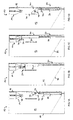
- the feeding system 10 includes as major components a roughage dosing device, generally designated 12, and a concentrate dosing device, generally designated 14.
- a roughage dosing device generally designated 12
- a concentrate dosing device generally designated 14.
- the power feed metering device 14 is disposed within the roughage metering device 12.
- the roughage dosing device 12 comprises a box-shaped, relatively large roughage container 16 for storing roughage, generally with a rectangular or square base size of for example 80x80cm and a height of, for example, 2m.
- the front wall 18 of the roughage container 16 is provided in the lower region with a first feed opening 20 for roughage. Behind the feeding opening 20 is an inclined bottom plate 22nd provided, through which the roughage (not shown) to the feeding opening 20 slides.
- For refilling the roughage container 16 is open at the top or in the rear wall with an opening or flap (not shown).
- the roughage dosing device 12 further comprises a slide 24 mounted vertically displaceable, which is arranged at a small distance behind the front wall 18.
- the slider 24 is provided with corresponding sockets not shown in detail in which engage the bars.
- another guide of known type can be provided for the slide.
- suitable drive means are provided, such as pneumatic lifting cylinder 28 (only in 2A shown schematically).
- Pneumatic lifting cylinders 28 are particularly suitable for the present application and avoid, for example, electrical lines to mains voltage in horse boxes, other drive means are also conceivable.
- the piston rods of the lifting cylinder 28 are directed downward and engage the lower end portion of the slider 24, as in FIG2A shown.
- at least one lower position sensor 30 and one upper position sensor 32 are provided.
- the position sensors 30, 32 may be in the form of inductive pneumatic standard components and arranged on one of the two lifting cylinders 28.
- the position sensors 30, 32 can also be designed differently, for example, as appropriately arranged light barriers, and are used in particular for controlling the power feed dosing.
- an actuating means 34 is arranged which cooperates for the metered delivery of concentrated feed with a dispenser of the power feed metering device 14.
- the actuating means comprises a Kraftfuttertrog 38 and a hinge by means of which the Kraftfuttertrog 38 is mounted centrally and pivotally about a horizontal axis at the upper end of the slider 24.
- a second feed opening 40 for concentrated feed is provided in the front wall 18 centrally above the feed opening 20 for roughage.
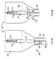
- This comprises a concentrate feed container 50, which is small in comparison to the roughage container 16, and a dispenser 36.
- the jacket of the container 50 is cylindrical in the upper region and conical in the lower region, so that the concentrate (not shown) of the dispenser 36 by gravity is supplied.
- the dispenser 36 includes a metering chamber 52 which is formed by two telescoping sleeves 54, 56.
- the metering chamber 52 preferably has a downwardly directed outlet opening 58 from which the metered concentrate (not shown) can leak.
- the metering chamber 52 is axially displaceable by means of a shaft 60 and a guide 62 against the force of a return spring 64, so that the metering chamber 52 can be inserted into the concentrate tank 50 and is ejected in the idle state.
- In the upper sleeve 54 of the metering chamber 52 one or more inlet openings 66 are provided.
- the inlet openings 66 are closed at rest by a pipe socket 68 at the lower end of the concentrate tank 50.
- the pipe socket 68 also serves as a guide for the metering chamber 52. In the inserted state, the metering chamber 52 fills under gravity through the inlet openings 66 with concentrated feed.
- the power metering device 14 makes it possible in a simple, passive design with each repeated and the same mechanical actuation dose the set to volume.
- the power feed metering device 14 therefore does not require its own drive and no associated power supply or control.
- the concentrate tank 50 may be open at the top or provided with a flap.
- 1A 2A show the feeding system 10 at rest. At rest, no feeding takes place.
- the flap 24 is in the closed position, ie it closes the roughage feeding opening 20 and the pivotable Kraftfuttertrog 38 is in its normal position, ie a substantially vertical emptying position behind the concentrate feed opening 40 and therefore contains no food.
- the emptying position of the power feeding trough 38 is thus oriented so that it provides no catchment area for incidental dirt and thus can not be contaminated by Koten.
- Kraftfuttertrog 38 and guide plate 44 also prevent unwanted access to roughage through the concentrate feed opening 40.
- 1B 2B show the feeding system 10 in a first feeding state.
- roughage is fed. This state is achieved in that the lifting cylinder 28, the slider 24 in its open position 1B Drive & 2B.
- the controller can determine that the slider is in the position according to 1B 2B, ie that the feeding system 10 is in the first feeding state.
- the roughage is accessible through the feed fence, ie the first feeding opening 20 for the farm animal. How out 1B can be seen the force feed trough 38 by the movement of the slider 24, on the in FIG.1D shown position, folded into a substantially horizontal operating position, in which the Kraftfuttertrog 38 rests with a wall on the support 42.
- the second feed opening 40 is closed by the slide 24.
- Figure 1C 2C show the feeding system 10 in an intermediate state in which the feeder-dose dispenser 36 is actuated. More precisely, the supported on the support wall 42 of the power trough 38 is driven upward by additional movement of the slider 24 based on the lifting cylinder 28 via the open position in 1B & 2B. By the raised Kraftfuttertrog 38, the metering chamber 52 is moved into the concentrate tank 50. In this intermediate state, the first feed opening 20 for roughage is still open and the second feed opening 40 for concentrated feed is still closed. The intermediate state is maintained by means of a control at least as long that the dosing chamber 52 can completely fill even at maximum dosing volume and very coarse-grained concentrated feed. The intermediate state according to Figure 1C & 2C is optional.
- this intermediate state can easily be skipped by the controller in that the slide 24 is moved out of the open position according to FIG 1B 2B (first feeding state) directly back to the closed position according to 1A & 2A (idle state) is driven.
- the controller in that the slide 24 is moved out of the open position according to FIG 1B 2B (first feeding state) directly back to the closed position according to 1A & 2A (idle state) is driven.
- the controller depending on the dosing volume and concentrate requirement, by repeated displacement of the power feed trough 38 between states 1B 2B and according to F1G.1C & 2C also a repeated power feed delivery into the Kraftfuttertrog 38 possible. In this way, larger amounts of concentrated feed can be dispensed into the Kraftfuttertrog 38 in multiple doses and fed in a feeding process.
- FIG.1D & 2D show the feeding system in a second feeding state.
- This second feeding state which follows the intermediate state according to F1G.1C & 2C, concentrated feed is fed.
- the condition according to FIG.1D & 2D is achieved in that the lifting cylinder 28, the slider 24 in a in FIG.1D & 2D shown slightly above the closed position at rest drive. The achievement of this position is determined by the lower position sensor 30.
- This position is chosen so that the Kraftfuttertrog 38 based on the guide plate 44 in the oblique feeding position FIG.1D is pivoted and held and not yet strikes the bars 26.
- the metered down in the power feeding trough power feed delivered to the livestock through the second feed opening 40 is accessible when descending.
- the roughage is no longer accessible, since the first feeding opening 20 is largely closed by the slide 24.
- the residence time in the second feeding state is adapted to the intake of the concentrated feed.
- the slider 24 is either immediately from the open position according to 1B & 2B (ie when no concentrated feed is to be dispensed) or from the intermediate position in FIG.1D & 2D (ie after allocation of concentrated feed) again completely down to the closed position in 1A & 2A driven.
- the Kraftfuttertrog 38 by the stop 27 on the bars 26 in his also in 1A 2A and 2A, whereby excess concentrated feed is ejected, ie the power feeding trough 38 is cleaned and, in particular, it is prevented that the livestock can permanently pollute the power feeding trough by killing.
- the concentrate metering device 114 comprises a concentrate feed container 150 of a similar configuration as the container 50, ie, the container 150 has a cylindrically shaped top to which a conically shaped base adjoins. However, the metering device 114 is provided with a different dispensing device 136 than the metering device 14 described above.
- the dispensing device 136 is arranged substantially in the lower region of the container 150 and will be explained in more detail below.
- the pipe socket 168 forms a guide for a plunger 174.
- the plunger 174 is through the pipe socket 168, for example.
- the pressing piston 174 is closed, except for an opening for a shaft 180, at the top and comprises over its entire length a closed cylindrical outer jacket.
- a guide tube 176 is arranged centrally and coaxially.
- a stop piston 178 is coaxial with the plunger 174 and slidably received in the guide tube 176.
- the stop piston 178 is rigidly connected to the plunger 174 via the shaft 180, for example a threaded rod.
- the shaft 180 is thin compared to the plunger 174, ie has a much smaller diameter.
- stop piston 178 By rigid connection between stop piston 178 and plunger 174 by means of the shaft 180 of the plunger 174 is held on the container 150.
- the distance between plunger 174 and stop piston 178 is adjustable, characterized in that the shaft 180 is fixed in the axial direction adjustable on the plunger 174, for example by means of screw or snap connection.
- the stopper piston 178 serves not only as a stop but also for improved leadership of the plunger 174 and possibly as additional weight, which helps to bring the self-weight returning plunger 174 after actuation (see below) by gravity back to its lower end position.
- the outer diameter of stop piston 178 and plunger 174 and the inner diameter of the guide tube 176 are tuned so that guided but smooth sliding of the two pistons 174, 178 within the guide tube 176 is made possible.
- 4a shows on the basis of dotted hatching a first adjusted concentrate volume 182 which is located in the lower part of the container 150 above the plunger 174.
- the power feed volume 182 corresponds approximately to a cylinder volume with the diameter of the plunger 174 and a height equal to the adjustable distance between the plunger 174 and stop piston 178, wherein the traversing volume of the shaft 180 is accounted.
- the plunger 174 is now pushed by means of thrust movement by means of the actuating means 34 on the slider 24 opposite to gravity, through the partial volume of the container 150 in which the concentrate feed volume 182 was originally located, upwards into the guide tube 176. As a result, the plunger 174 simultaneously displaces the entire concentrate volume 182 from the container 150 into the guide tube 176.
- the corresponding subsequent, upper operating position of the plunger 174 is in 4B is shown and is reached when the actuating means 34 rests against the lower end of the pipe socket 168.
- the dispenser 136 allows metered delivery of concentrated feed.
- the dosage can be adjusted by changing the distance between plunger 174 and stopper piston 178 by means of the adjustable attachment of shaft 180 to plunger 174. This can be compared to, for example 4B set a larger concentrate volume 182 'at an increased distance, as indicated by dotted hatching in 4C shown.
- the overall length of the plunger 174 may be selected to be approximately fully extended from the bottom of the spud 168 to the orifice of the spout 184 in the draft tube 176. Further, the lower end of the draft tube 176 may be designed to be widening downwardly to prevent the introduction of the To facilitate concentrated feed. It should be noted that the metering device 114, as well as the metering device 14, not only adjustable but also completely passive and is designed for mechanical interaction with an actuating means 34 on the slider 24 of the roughage metering device 10 is suitable.
- the description of the automatic feeding system 10 is based on the 1A-D and 2A-D accordingly also when, instead of a metering device 14 according to 3A-B , a metering device 114 according to 4A-C used in the feeding system 10.
- a metering device 114 according to 4A-C used in the feeding system 10.
- the total volume of the container 50; 150 each is about 401, wherein the dosing volume of the power chuck can be set between 0.3 and 0.61, for example.
- metering devices 14 or 114 can be used in the feeding system 3A & B respectively.
- 4A-C parallel, arranged off-center, optionally with corresponding separate troughs.
- Each of the concentrate feeders according to 3A & B or the 4A-C is considered a preferred, in and of itself already inventive design. These could, however, be replaced by other passive, purely mechanically actuated metering devices without losing the advantages of the claimed invention.
- a power feeding trough 38 pivotally mounted on the slide 24 is particularly preferred because of the possibility of emptying and the associated hygiene.
- An external power trough can be filled with concentrate via a feed chute, for example starting from the outlet 184 of a metering device 114 4A-C ,
- inventive feeding systems in a stable individual concentrate feeders 14; 114 readily via a filling system, such as in the international patent application WO 95 10180 (to Fig.7) describe automatically filled. Retrofitting existing roughage feeders with an actuating means and a hereby co-acting concentrate feeder is within the Invention also possible and, especially when using a fixed Kraftfuttertrogs, relatively inexpensive.
Landscapes
- Life Sciences & Earth Sciences (AREA)
- Environmental Sciences (AREA)
- Birds (AREA)
- Animal Husbandry (AREA)
- Biodiversity & Conservation Biology (AREA)
- Feeding And Watering For Cattle Raising And Animal Husbandry (AREA)
Priority Applications (3)
| Application Number | Priority Date | Filing Date | Title |
|---|---|---|---|
| EP08151125A EP2087788A1 (fr) | 2008-02-06 | 2008-02-06 | Système de nourriture automatique en particulier pour chevaux |
| EP09708793A EP2242355A1 (fr) | 2008-02-06 | 2009-02-06 | Système d'affouragement automatique, en particulier pour chevaux |
| PCT/EP2009/051363 WO2009098281A1 (fr) | 2008-02-06 | 2009-02-06 | Système d'affouragement automatique, en particulier pour chevaux |
Applications Claiming Priority (1)
| Application Number | Priority Date | Filing Date | Title |
|---|---|---|---|
| EP08151125A EP2087788A1 (fr) | 2008-02-06 | 2008-02-06 | Système de nourriture automatique en particulier pour chevaux |
Publications (1)
| Publication Number | Publication Date |
|---|---|
| EP2087788A1 true EP2087788A1 (fr) | 2009-08-12 |
Family
ID=39597830
Family Applications (2)
| Application Number | Title | Priority Date | Filing Date |
|---|---|---|---|
| EP08151125A Withdrawn EP2087788A1 (fr) | 2008-02-06 | 2008-02-06 | Système de nourriture automatique en particulier pour chevaux |
| EP09708793A Withdrawn EP2242355A1 (fr) | 2008-02-06 | 2009-02-06 | Système d'affouragement automatique, en particulier pour chevaux |
Family Applications After (1)
| Application Number | Title | Priority Date | Filing Date |
|---|---|---|---|
| EP09708793A Withdrawn EP2242355A1 (fr) | 2008-02-06 | 2009-02-06 | Système d'affouragement automatique, en particulier pour chevaux |
Country Status (2)
| Country | Link |
|---|---|
| EP (2) | EP2087788A1 (fr) |
| WO (1) | WO2009098281A1 (fr) |
Cited By (3)
| Publication number | Priority date | Publication date | Assignee | Title |
|---|---|---|---|---|
| CN105325310A (zh) * | 2015-11-03 | 2016-02-17 | 中国农业科学院北京畜牧兽医研究所 | 一种哺乳母猪精确下料系统 |
| CN106942080A (zh) * | 2017-03-29 | 2017-07-14 | 广东省现代农业装备研究所 | 一种猪用自动喂料装置及其使用方法 |
| RU234122U1 (ru) * | 2024-10-25 | 2025-05-21 | Федеральное государственное бюджетное образовательное учреждение высшего образования "Орловский государственный аграрный университет им. Н.В. Парахина" (ФГБОУ ВО Орловский ГАУ) | Автоматическая кормушка для лошадей |
Families Citing this family (1)
| Publication number | Priority date | Publication date | Assignee | Title |
|---|---|---|---|---|
| DE202016101488U1 (de) | 2016-03-01 | 2016-06-14 | Pro-Cast Gmbh | Behälter zur Bevorratung verschiedener schüttfähiger und/oder fließfähiger Güter |
Citations (8)
| Publication number | Priority date | Publication date | Assignee | Title |
|---|---|---|---|---|
| GB190920898A (en) * | 1909-09-13 | 1909-12-16 | August Rudolph Hoffman | Improvements in Apparatus for Supplying Food in Regulated or Measured Quantities to Animals. |
| GB2165131A (en) * | 1984-10-05 | 1986-04-09 | Gunyah Nominees Pty Ltd | A feeding apparatus for animals |
| DE4321140A1 (de) | 1992-06-30 | 1994-01-27 | Bolz Alfred Gmbh Co Kg | Dosieranlage für Trockenfutter für Pferde und dergleichen |
| WO1995010180A1 (fr) | 1993-10-08 | 1995-04-20 | Ctb Inc. | Procede et appareil utilises pour nourrir des chevaux |
| DE29905742U1 (de) * | 1999-03-29 | 1999-07-15 | Wieczorek, Hans-Jürgen, Dipl.-Betriebw., 25764 Norddeich | Fütterungseinrichtung für Tiere, schwenkbare Silos für Kraft- und Rauchfutter |
| DE202005006093U1 (de) | 2005-04-16 | 2005-06-23 | Gadow, Frank, Dipl.-Ing. agr. | Mobile Rauhfutterstation für Pferde |
| DE102004029703A1 (de) * | 2004-01-28 | 2005-08-18 | Grünewald, Falco | Einzelfutterautomat für Pferde |
| DE202005011187U1 (de) * | 2005-07-13 | 2005-09-22 | Ernst, Dieter | Futtervorrichtung für Pferde |
-
2008
- 2008-02-06 EP EP08151125A patent/EP2087788A1/fr not_active Withdrawn
-
2009
- 2009-02-06 WO PCT/EP2009/051363 patent/WO2009098281A1/fr not_active Ceased
- 2009-02-06 EP EP09708793A patent/EP2242355A1/fr not_active Withdrawn
Patent Citations (8)
| Publication number | Priority date | Publication date | Assignee | Title |
|---|---|---|---|---|
| GB190920898A (en) * | 1909-09-13 | 1909-12-16 | August Rudolph Hoffman | Improvements in Apparatus for Supplying Food in Regulated or Measured Quantities to Animals. |
| GB2165131A (en) * | 1984-10-05 | 1986-04-09 | Gunyah Nominees Pty Ltd | A feeding apparatus for animals |
| DE4321140A1 (de) | 1992-06-30 | 1994-01-27 | Bolz Alfred Gmbh Co Kg | Dosieranlage für Trockenfutter für Pferde und dergleichen |
| WO1995010180A1 (fr) | 1993-10-08 | 1995-04-20 | Ctb Inc. | Procede et appareil utilises pour nourrir des chevaux |
| DE29905742U1 (de) * | 1999-03-29 | 1999-07-15 | Wieczorek, Hans-Jürgen, Dipl.-Betriebw., 25764 Norddeich | Fütterungseinrichtung für Tiere, schwenkbare Silos für Kraft- und Rauchfutter |
| DE102004029703A1 (de) * | 2004-01-28 | 2005-08-18 | Grünewald, Falco | Einzelfutterautomat für Pferde |
| DE202005006093U1 (de) | 2005-04-16 | 2005-06-23 | Gadow, Frank, Dipl.-Ing. agr. | Mobile Rauhfutterstation für Pferde |
| DE202005011187U1 (de) * | 2005-07-13 | 2005-09-22 | Ernst, Dieter | Futtervorrichtung für Pferde |
Cited By (4)
| Publication number | Priority date | Publication date | Assignee | Title |
|---|---|---|---|---|
| CN105325310A (zh) * | 2015-11-03 | 2016-02-17 | 中国农业科学院北京畜牧兽医研究所 | 一种哺乳母猪精确下料系统 |
| CN105325310B (zh) * | 2015-11-03 | 2017-12-05 | 中国农业科学院北京畜牧兽医研究所 | 一种哺乳母猪精确下料系统 |
| CN106942080A (zh) * | 2017-03-29 | 2017-07-14 | 广东省现代农业装备研究所 | 一种猪用自动喂料装置及其使用方法 |
| RU234122U1 (ru) * | 2024-10-25 | 2025-05-21 | Федеральное государственное бюджетное образовательное учреждение высшего образования "Орловский государственный аграрный университет им. Н.В. Парахина" (ФГБОУ ВО Орловский ГАУ) | Автоматическая кормушка для лошадей |
Also Published As
| Publication number | Publication date |
|---|---|
| EP2242355A1 (fr) | 2010-10-27 |
| WO2009098281A1 (fr) | 2009-08-13 |
Similar Documents
| Publication | Publication Date | Title |
|---|---|---|
| DE60102921T2 (de) | Selbsttättige fütterungsvorrichtung | |
| EP0741965B1 (fr) | Mangeoire pour animaux domestiques, en particulier des porcs | |
| DE3138089A1 (de) | "vorrichtung zum zufuehren von elektrischen schaltungselementen zu einem schaltungsmontageplatz" | |
| DE69806324T2 (de) | Futterdosiervorrichtung | |
| DE102007044178A1 (de) | Pneumatische Sämaschine | |
| EP3598893B1 (fr) | Doseur volumétrique, installation d'alimentation pour animaux et procédé de fourniture de l'aliment pour animaux | |
| EP2242355A1 (fr) | Système d'affouragement automatique, en particulier pour chevaux | |
| DE69603327T2 (de) | Vorrichtung zur Entnahme von Milchproben | |
| EP0856252A2 (fr) | Procédé et dispositif pour faire fonctionner un appareil mangeoire sensiblement automatique | |
| DE10010781B4 (de) | Verfahren und Vorrichtung zum Füttern von Tieren | |
| DE202018104323U1 (de) | Volumendosierer und Fütterungsanlage | |
| DE3805149C1 (en) | Arrangement for charging feed places or troughs | |
| DE202021100751U1 (de) | Futtertrog für Tiere | |
| DE2620686A1 (de) | Einrichtung zum automatischen fuettern von tieren mit nassfutter | |
| DE10345127A1 (de) | Verfahren und Vorrichtung zum Füttern von Tieren, insbesondere Schweinen | |
| DE29700720U1 (de) | Fütterungsvorrichtung, insbesondere für die Fütterung von Ferkeln | |
| EP3302921A1 (fr) | Dispositif d'extrusion et procédé d'extrusion pour la fabrication d'un film plastique | |
| DE19718076C2 (de) | Selbstmixfütterer | |
| DE19739346C1 (de) | Fütterungsvorrichtung für Tiere, insbesondere Schweine | |
| DE1816322A1 (de) | Fuetterungsvorrichtung,insbesondere fuer Schweine | |
| AT524254B1 (de) | Futterabgabeanlage zur Versorgung von Tieren mit Tiernahrung | |
| DE1965703C3 (de) | Automatisch arbeitende Vorrichtung zur Zuteilung von Futter für Schweine | |
| AT295232B (de) | Fütterungsanlage, insbesondere für Shweineställe | |
| EP1743519A1 (fr) | Installation de distribution de nouriture pour chevaux | |
| DE3304366C1 (de) | Einrichtung zum Befüllen von Futterstellen |
Legal Events
| Date | Code | Title | Description |
|---|---|---|---|
| PUAI | Public reference made under article 153(3) epc to a published international application that has entered the european phase |
Free format text: ORIGINAL CODE: 0009012 |
|
| AK | Designated contracting states |
Kind code of ref document: A1 Designated state(s): AT BE BG CH CY CZ DE DK EE ES FI FR GB GR HR HU IE IS IT LI LT LU LV MC MT NL NO PL PT RO SE SI SK TR |
|
| AX | Request for extension of the european patent |
Extension state: AL BA MK RS |
|
| AKX | Designation fees paid | ||
| REG | Reference to a national code |
Ref country code: DE Ref legal event code: 8566 |
|
| STAA | Information on the status of an ep patent application or granted ep patent |
Free format text: STATUS: THE APPLICATION IS DEEMED TO BE WITHDRAWN |
|
| 18D | Application deemed to be withdrawn |
Effective date: 20100213 |