EP2087950B1 - Verfahren zum Umformen eines Werkstücks mit nicht-kreisförmiger Zylinderform und Vorrichtung dafür - Google Patents
Verfahren zum Umformen eines Werkstücks mit nicht-kreisförmiger Zylinderform und Vorrichtung dafür Download PDFInfo
- Publication number
- EP2087950B1 EP2087950B1 EP08171690A EP08171690A EP2087950B1 EP 2087950 B1 EP2087950 B1 EP 2087950B1 EP 08171690 A EP08171690 A EP 08171690A EP 08171690 A EP08171690 A EP 08171690A EP 2087950 B1 EP2087950 B1 EP 2087950B1
- Authority
- EP
- European Patent Office
- Prior art keywords
- work piece
- cylindrical shape
- circular cylindrical
- minor axis
- spindle
- Prior art date
- Legal status (The legal status is an assumption and is not a legal conclusion. Google has not performed a legal analysis and makes no representation as to the accuracy of the status listed.)
- Not-in-force
Links
Images



Classifications
-
- B—PERFORMING OPERATIONS; TRANSPORTING
- B21—MECHANICAL METAL-WORKING WITHOUT ESSENTIALLY REMOVING MATERIAL; PUNCHING METAL
- B21D—WORKING OR PROCESSING OF SHEET METAL OR METAL TUBES, RODS OR PROFILES WITHOUT ESSENTIALLY REMOVING MATERIAL; PUNCHING METAL
- B21D22/00—Shaping without cutting, by stamping, spinning, or deep-drawing
- B21D22/14—Spinning
-
- B—PERFORMING OPERATIONS; TRANSPORTING
- B21—MECHANICAL METAL-WORKING WITHOUT ESSENTIALLY REMOVING MATERIAL; PUNCHING METAL
- B21D—WORKING OR PROCESSING OF SHEET METAL OR METAL TUBES, RODS OR PROFILES WITHOUT ESSENTIALLY REMOVING MATERIAL; PUNCHING METAL
- B21D41/00—Application of procedures in order to alter the diameter of tube ends
- B21D41/04—Reducing; Closing
-
- F—MECHANICAL ENGINEERING; LIGHTING; HEATING; WEAPONS; BLASTING
- F01—MACHINES OR ENGINES IN GENERAL; ENGINE PLANTS IN GENERAL; STEAM ENGINES
- F01N—GAS-FLOW SILENCERS OR EXHAUST APPARATUS FOR MACHINES OR ENGINES IN GENERAL; GAS-FLOW SILENCERS OR EXHAUST APPARATUS FOR INTERNAL-COMBUSTION ENGINES
- F01N13/00—Exhaust or silencing apparatus characterised by constructional features
- F01N13/18—Construction facilitating manufacture, assembly, or disassembly
- F01N13/1872—Construction facilitating manufacture, assembly, or disassembly the assembly using stamp-formed parts or otherwise deformed sheet-metal
-
- Y—GENERAL TAGGING OF NEW TECHNOLOGICAL DEVELOPMENTS; GENERAL TAGGING OF CROSS-SECTIONAL TECHNOLOGIES SPANNING OVER SEVERAL SECTIONS OF THE IPC; TECHNICAL SUBJECTS COVERED BY FORMER USPC CROSS-REFERENCE ART COLLECTIONS [XRACs] AND DIGESTS
- Y10—TECHNICAL SUBJECTS COVERED BY FORMER USPC
- Y10T—TECHNICAL SUBJECTS COVERED BY FORMER US CLASSIFICATION
- Y10T29/00—Metal working
- Y10T29/49—Method of mechanical manufacture
- Y10T29/49345—Catalytic device making
-
- Y—GENERAL TAGGING OF NEW TECHNOLOGICAL DEVELOPMENTS; GENERAL TAGGING OF CROSS-SECTIONAL TECHNOLOGIES SPANNING OVER SEVERAL SECTIONS OF THE IPC; TECHNICAL SUBJECTS COVERED BY FORMER USPC CROSS-REFERENCE ART COLLECTIONS [XRACs] AND DIGESTS
- Y10—TECHNICAL SUBJECTS COVERED BY FORMER USPC
- Y10T—TECHNICAL SUBJECTS COVERED BY FORMER US CLASSIFICATION
- Y10T29/00—Metal working
- Y10T29/49—Method of mechanical manufacture
- Y10T29/496—Multiperforated metal article making
- Y10T29/49604—Filter
-
- Y—GENERAL TAGGING OF NEW TECHNOLOGICAL DEVELOPMENTS; GENERAL TAGGING OF CROSS-SECTIONAL TECHNOLOGIES SPANNING OVER SEVERAL SECTIONS OF THE IPC; TECHNICAL SUBJECTS COVERED BY FORMER USPC CROSS-REFERENCE ART COLLECTIONS [XRACs] AND DIGESTS
- Y10—TECHNICAL SUBJECTS COVERED BY FORMER USPC
- Y10T—TECHNICAL SUBJECTS COVERED BY FORMER US CLASSIFICATION
- Y10T29/00—Metal working
- Y10T29/49—Method of mechanical manufacture
- Y10T29/49826—Assembling or joining
- Y10T29/49908—Joining by deforming
- Y10T29/49909—Securing cup or tube between axially extending concentric annuli
- Y10T29/49913—Securing cup or tube between axially extending concentric annuli by constricting outer annulus
-
- Y—GENERAL TAGGING OF NEW TECHNOLOGICAL DEVELOPMENTS; GENERAL TAGGING OF CROSS-SECTIONAL TECHNOLOGIES SPANNING OVER SEVERAL SECTIONS OF THE IPC; TECHNICAL SUBJECTS COVERED BY FORMER USPC CROSS-REFERENCE ART COLLECTIONS [XRACs] AND DIGESTS
- Y10—TECHNICAL SUBJECTS COVERED BY FORMER USPC
- Y10T—TECHNICAL SUBJECTS COVERED BY FORMER US CLASSIFICATION
- Y10T29/00—Metal working
- Y10T29/49—Method of mechanical manufacture
- Y10T29/49826—Assembling or joining
- Y10T29/49908—Joining by deforming
- Y10T29/49925—Inward deformation of aperture or hollow body wall
- Y10T29/49927—Hollow body is axially joined cup or tube
Definitions
- the present invention concerns a drawing method for performing drawing to the end part of a work piece in non-circular cylindrical shape according to the preamble of claim 1 or, more particularly, a work piece in elliptical shape including ellipse and flat part.
- An apparatus suitable for carrying out the method according to the invention is also described.
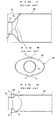
- Fig. 7 to Fig. 9 indicate an example in which drawing was made by a conventional method on a work piece W in non-circular cylindrical shape, a work piece in elliptical shape for example, to manufacture a muffler 50 for automobile.
- This working method consists in forming an end part of the work piece W in elliptical shape into an inclined face 52 inclined in a way to get smaller in diameter gradually, and performing drawing, for forming a certain length of that end part into a circular cylindrical shape 51 with prescribed diameter, to both end parts of the work piece W, to make it into a product 50 (muffler for automobile).
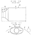
- This working method consists in forming, as shown in Fig. 10 to 11 , an end part of the work piece W in elliptical shape into an inclined face 33 inclined in a way to get smaller in diameter gradually, and moving the work piece W, which has been submitted to drawing for forming a certain length of its end part into a circular cylindrical shape 32 with prescribed diameter, in the radial direction of minor axis (upward in Fig.
- the above-described working method proposed by the present applicant has an advantage of enabling to obtain a muffler for automobile 30 without swollen part b, while on the other hand it had a problem of causing creases or depression on the formed face 34 because the drawing roller R gets in contact with the swollen part b, positioned on the drawing roller R side with reference to the working locus A' of the drawing roller R, right from the side face and temporarily apply a heavy load to the swollen part b, making any smooth drawing difficult.
- the objective of the present invention realized in view of such problems of the above-described conventional drawing methods of work piece in non-circular cylindrical shape, is to provide a drawing method of work piece in non-circular cylindrical shape capable of eliminating the swollen part, without causing any creases or depression on the formed face, by performing drawing to the swollen part produced in a region near the minor axis of the work piece in non-circular cylindrical shape.
- the drawing method of work piece in non-circular cylindrical shape is a drawing method using a spindle mechanism provided with a drawing roller at the tip of the spindle and a work piece holding mechanism for holding the work piece in non-circular cylindrical shape disposed face to face with the spindle mechanism, for drawing the end part of said work piece into a circular cylindrical shape, characterized in that it consists in performing drawing for forming the end part of the work piece into an inclined face inclined in a way to get smaller in diameter gradually, and then performing drawing to the swollen part produced in a region near the minor axis of the work piece by displacing the work piece by a prescribed angle in the plane containing the minor axis plane of the work piece in non-circular cylindrical shape.
- the drawing method of work piece in non-circular cylindrical shape of the present invention by performing drawing for forming an end part of the work piece into an inclined face inclined in a way to get smaller in diameter gradually, and then performing drawing to the swollen part in a region near the minor axis of the work piece by displacing the work piece by a prescribed angle in the plane containing the minor axis plane of the work piece in non-circular cylindrical shape, it becomes possible to eliminate the swollen part, without causing any creases or depression on the formed face, because the working locus of the drawing roller becomes a smooth curve along the ridgeline of the swollen part, without temporarily applying any heavy load to the swollen part, thereby enabling to perform drawing smoothly.
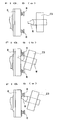
- Fig. 1 to Fig. 6 show an embodiment of the drawing method of work piece in non-circular cylindrical shape according to the present invention and of an apparatus for carrying out this method.
- This drawing apparatus 1 of work piece in non-circular cylindrical shape is constructed by comprising, as shown in Fig. 1 to Fig. 4 , a spindle mechanism 2 provided with a drawing roller R at the tip of the spindle 7, and a work piece holding mechanism 3 for holding the work piece W in non-circular cylindrical shape.
- the spindle mechanism 2 is constructed in a way to be movable by a driving mechanism (not illustrated), on a travelling rail 6 installed on a base 5, so that the spindle mechanism 2 may be either in contact with or away from the work piece holding mechanism 3. It is also possible to provide a similar moving mechanism on the work piece holding mechanism 3, to enable the spindle mechanism 2 and the work piece holding mechanism 3 to get in contact with or get away from each other.
- a tool mount 10 supporting the drawing roller R as tool is constructed by comprising, as main component parts, a tool supporting member 11 directly supporting the drawing roller R as tool, a main mount 13 provided with a guide groove 12 for guiding this tool supporting member 11 in the radial direction, and a cam plate 14 provided with a spiral groove 15 for moving the drawing roller R in the radial direction.
- the main mount 13 is installed by fixing to the mounting flange 8.
- To the tool supporting member 11 is attached a guide pin 16, and this guide pin 16 is designed to be inserted in the spiral groove 15.
- the spindle 7 has a hollow structure, so that a cam shaft 17 provided with a cam plate 14 at its tip may be inserted in the spindle 7, to connect the spindle 7 and the cam shaft 17 to each other through an appropriate speed-change mechanism V.
- Reference mark C indicates the operating mechanism of this speed-change mechanism
- reference mark M represents a driving motor.
- reference numeral 19 indicates a mandrel inserted in the work piece W in non-circular cylindrical shape
- reference numeral 18 represents a connecting rod for making the mandrel 19 move forward and backward, connected to an appropriate cylinder (not illustrated).
- the work piece holding mechanism 3 intended for holding a work piece W in non-circular cylindrical shape or, more concretely, a work piece W in elliptical shape including ellipse and flat part, comprises a lower fixed claw 20 and a upper lifting claw 21, a lifting frame 23 provided with a cylinder 22 for lifting this lifting claw 21, a supporting frame 24 for supporting this lifting frame 23 in a way to allow going up and down, and a fixed base 25 for supporting this supporting frame 24 in a way to allow moving in the transversal direction (left-right direction in Fig. 2 ).
- the lower fixed claw 20 and the upper lifting claw 21 of the work piece holding mechanism 3 are constructed, in this embodiment, in such a way that the minor axis plane of the work piece W in non-circular cylindrical shape held by the lower fixed claw 20 and the upper lifting claw 21 agrees with a horizontal plane.
- the shape, etc. of the lower fixed claw 20 and the upper lifting claw 21 of the work piece holding mechanism 3 is not restricted to that of this embodiment, but may be modified as required depending on the shape, etc. of the work piece W to be held.
- the work piece holding mechanism 3 is provided, in addition to the above-described moving mechanism, with a slewing mechanism 9 of the supporting frame 24 as displacing mechanism for displacing the work piece W by a prescribed angle in the plane containing the minor axis plane of the work piece W in non-circular cylindrical shape (on a horizontal plane, in this embodiment).
- Fig. 6 perform drawing, by a working method similar to the conventional working method, to one end part of the work piece W in non-circular cylindrical shape, or in elliptical cylindrical shape for example, into an inclined face 33 inclined in a way to get smaller in diameter gradually, and form a certain length of that end part into a circular cylindrical shape 32 with prescribed diameter, as required.
- This drawing does not temporarily produce any large load on the swollen part b, unlike the case of the conventional working method in which the drawing roller R gets in contact right from the side face with the swollen part b which is positioned on the roller R side with reference to the working locus A' of the roller R, because the working locus A of the drawing roller R forms a smooth curve along the ridgeline of the swollen part b, as shown in Fig. 6 (a) , thus enabling to perform drawing smoothly and eliminate the swollen part b, without causing any creases or depression on the formed face.
- the drawing method of work piece in non-circular cylindrical shape and apparatus for it according to the present invention are capable of eliminating swollen part, without causing any creases or depression on the formed face, by performing drawing to the swollen part produced in a region near the minor axis of the work piece in non-circular cylindrical shape and, for that reason, they can be used suitably in the case where the end part of a work piece in non-circular cylindrical shape is formed into an inclined face inclined in a way to get smaller in diameter gradually.
Landscapes
- Engineering & Computer Science (AREA)
- Mechanical Engineering (AREA)
- Chemical & Material Sciences (AREA)
- Combustion & Propulsion (AREA)
- General Engineering & Computer Science (AREA)
- Shaping Metal By Deep-Drawing, Or The Like (AREA)
- Metal Extraction Processes (AREA)
- Bending Of Plates, Rods, And Pipes (AREA)
Claims (2)
- Umformungsverfahren zum Ausführen eines Umformungsvorgangs an dem Endteil eines Werkstücks (W) mit nicht kreisförmiger Zylinderform unter Verwendung eines Spindelmechanismus (2), der mit einer Umformungsrolle (R) am Ende der Spindel (7) versehen ist, sowie unter Verwendung eines Werkstück-Haltemechanismus (3) zum Halten des Werkstücks (W) mit nicht kreisförmiger Zylinderform in einer dem Spindelmechanismus (2) stirnseitig zugewandten Anordnung zum Umformen des Endteils des Werkstücks in eine kreisförmige Zylinderform,
dadurch gekennzeichnet,
daß das Verfahren folgende Schritte aufweist:Ausführen eines Umformungsvorgangs zum Formen des Endteils des Werkstücks zu einer schräg verlaufenden Fläche mit einer derartigen Neigung, daß es im Durchmesser allmählich geringer wird, und anschließendes Ausführen eines Umformungsvorgangs an dem angeschwollenen Teil (b), das in einem Bereich in der Nähe der kleineren Achse des Werkstücks gebildet ist, durch Verlagern des Werkstücks um einen vorbestimmten Winkel in der Ebene, die die Ebene der kleineren Achse des Werkstücks mit nicht kreisförmiger Zylinderform enthält. - Umformungsverfahren zum Umformen des Endteils des Werkstücks (W) in eine kreisförmige Zylinderform nach Anspruch 1,
wobei das Werkstück (W), das um einen vorbestimmten Winkel in der Ebene, die die Ebene der kleineren Achse des Werkstücks (W) mit nicht kreisförmiger Zylinderform enthält, verlagert worden ist, in der Ebene bewegt wird, während ein Umformungsvorgang an dem angeschwollenen Teil (b) ausgeführt wird, der in einem Bereich in der Nähe der kleineren Achse des Werkstücks (W) gebildet ist.
Applications Claiming Priority (1)
| Application Number | Priority Date | Filing Date | Title |
|---|---|---|---|
| JP2008026449A JP4485579B2 (ja) | 2008-02-06 | 2008-02-06 | 非円形筒状の被加工材料の絞り加工方法 |
Publications (2)
| Publication Number | Publication Date |
|---|---|
| EP2087950A1 EP2087950A1 (de) | 2009-08-12 |
| EP2087950B1 true EP2087950B1 (de) | 2010-11-03 |
Family
ID=40749828
Family Applications (1)
| Application Number | Title | Priority Date | Filing Date |
|---|---|---|---|
| EP08171690A Not-in-force EP2087950B1 (de) | 2008-02-06 | 2008-12-15 | Verfahren zum Umformen eines Werkstücks mit nicht-kreisförmiger Zylinderform und Vorrichtung dafür |
Country Status (6)
| Country | Link |
|---|---|
| US (1) | US8091231B2 (de) |
| EP (1) | EP2087950B1 (de) |
| JP (1) | JP4485579B2 (de) |
| CN (1) | CN101502859B (de) |
| AT (1) | ATE487034T1 (de) |
| DE (1) | DE602008003296D1 (de) |
Families Citing this family (4)
| Publication number | Priority date | Publication date | Assignee | Title |
|---|---|---|---|---|
| JP4698890B2 (ja) * | 2001-03-28 | 2011-06-08 | 坂本工業株式会社 | 異形管の突出部の加工方法 |
| JP6126439B2 (ja) * | 2013-04-03 | 2017-05-10 | 株式会社 クニテック | スピニング加工方法およびスピニング加工装置 |
| JP6236346B2 (ja) * | 2014-04-15 | 2017-11-22 | 株式会社三五 | ワーク加工装置とそれに用いる把持ユニット |
| CN109026315A (zh) * | 2018-07-25 | 2018-12-18 | 安徽江淮汽车集团股份有限公司 | 排气尾管 |
Family Cites Families (18)
| Publication number | Priority date | Publication date | Assignee | Title |
|---|---|---|---|---|
| JP2922201B1 (ja) * | 1998-07-21 | 1999-07-19 | 株式会社三五 | スピニング加工法とその装置 |
| JP2000051961A (ja) * | 1998-08-05 | 2000-02-22 | Fuji Kikai Kosakusho:Kk | 円筒体の端部絞り装置 |
| US6233993B1 (en) * | 1999-05-10 | 2001-05-22 | Sango Co., Ltd. | Method and apparatus for forming a processed portion of a workpiece |
| US6591498B2 (en) * | 1999-08-03 | 2003-07-15 | Sango Co., Ltd. | Method of producing a catalytic converter |
| US6381843B1 (en) * | 1999-08-03 | 2002-05-07 | Sango Co., Ltd. | Method of producing a catalytic converter |
| JP2001257256A (ja) | 2000-03-09 | 2001-09-21 | Mitsubishi Electric Corp | 保持カセット、保持ハンド、ウェット処理方法およびウェット処理装置 |
| JP2001259749A (ja) * | 2000-03-15 | 2001-09-25 | Calsonic Kansei Corp | パイプの成形方法 |
| US20020062562A1 (en) * | 2000-11-27 | 2002-05-30 | Houliang Li | Method of spin forming oblique end cones of a catalytic converter |
| JP2002172429A (ja) * | 2000-12-01 | 2002-06-18 | Nippon Spindle Mfg Co Ltd | 円筒形状の被加工材料に対する成形加工方法及びその装置 |
| JP4698890B2 (ja) * | 2001-03-28 | 2011-06-08 | 坂本工業株式会社 | 異形管の突出部の加工方法 |
| JP4647140B2 (ja) * | 2001-06-26 | 2011-03-09 | 坂本工業株式会社 | 管端の成形方法 |
| US6769281B2 (en) * | 2002-03-05 | 2004-08-03 | Sango Co., Ltd. | Method and apparatus of producing a columnar member container |
| NL1020171C2 (nl) * | 2002-03-13 | 2003-09-16 | Johan Massee | Werkwijze en forceermachine voor het bewerken van een werkstuk. |
| US6701617B2 (en) * | 2002-08-06 | 2004-03-09 | Visteon Global Technologies, Inc. | Spin-forming method for making catalytic converter |
| CN2614812Y (zh) * | 2003-04-11 | 2004-05-12 | 深圳市宝安区西乡镇臣田唐锋电器厂 | 自动旋压拉伸机 |
| JP2004353549A (ja) * | 2003-05-29 | 2004-12-16 | Sango Co Ltd | ハニカム構造体内蔵流体処理装置の製造方法 |
| US7316142B2 (en) * | 2004-05-21 | 2008-01-08 | Lancaster Paul B | Metal spin forming head |
| JP4436199B2 (ja) * | 2004-07-12 | 2010-03-24 | 新日本製鐵株式会社 | テーパー鋼管の製造装置 |
-
2008
- 2008-02-06 JP JP2008026449A patent/JP4485579B2/ja not_active Expired - Fee Related
- 2008-10-09 CN CN200810166451.7A patent/CN101502859B/zh not_active Expired - Fee Related
- 2008-12-15 DE DE602008003296T patent/DE602008003296D1/de active Active
- 2008-12-15 AT AT08171690T patent/ATE487034T1/de not_active IP Right Cessation
- 2008-12-15 EP EP08171690A patent/EP2087950B1/de not_active Not-in-force
- 2008-12-30 US US12/345,978 patent/US8091231B2/en not_active Expired - Fee Related
Also Published As
| Publication number | Publication date |
|---|---|
| JP4485579B2 (ja) | 2010-06-23 |
| US20090193870A1 (en) | 2009-08-06 |
| DE602008003296D1 (de) | 2010-12-16 |
| ATE487034T1 (de) | 2010-11-15 |
| US8091231B2 (en) | 2012-01-10 |
| CN101502859A (zh) | 2009-08-12 |
| CN101502859B (zh) | 2013-04-24 |
| JP2009183979A (ja) | 2009-08-20 |
| EP2087950A1 (de) | 2009-08-12 |
Similar Documents
| Publication | Publication Date | Title |
|---|---|---|
| US7134310B2 (en) | Tube bender | |
| US6823704B2 (en) | Apparatus and method of forming cylindrical work piece | |
| US4604885A (en) | Machine for the bending of stranded material | |
| US8091231B2 (en) | Spinning method of a work piece in a non-circular cylindrical shape and apparatus for the same | |
| KR101484451B1 (ko) | 밴딩머신 | |
| EP0916426A1 (de) | Verfahren und Vorrichtung zum Formen des Endteiles eines zylindrischen Werkstücks | |
| KR102315372B1 (ko) | 냉매 관 절단장치 | |
| CN110154003A (zh) | 一种用于汽车碰撞试验的变结构绳牵引并联机器人 | |
| CN112475943A (zh) | 一种不锈钢方形管万向斜切机台 | |
| US6250123B1 (en) | Method, apparatus and rack for making power transmission member | |
| SE526757C2 (sv) | Låsanordning med rörlig kuliss | |
| CN220216351U (zh) | 一种可用于折弯扁管的弯管机 | |
| CN211071299U (zh) | 皮带拉拔机 | |
| JP2007007682A (ja) | 円筒成形溶接機 | |
| CN218362699U (zh) | 一种应用于环状首饰的三维立体式激光焊接装置 | |
| JP2004249376A (ja) | 圧入装置および圧入方法 | |
| KR102684129B1 (ko) | 트라이포드 조인트용 볼 베어링 모듈 제조방법 및 제조장치 | |
| JP2005052851A (ja) | スクリュー羽根の成形方法及びスクリュー羽根成形装置 | |
| KR102021319B1 (ko) | 파이프 개선장치의 제어방법 | |
| JP2003062620A (ja) | 非円形筒状素材の端部絞り加工方法 | |
| JP2018009443A (ja) | 被締付部材緊解機及び被締付部材緊解機用ソケット | |
| CN114084636A (zh) | 变速器的自动化装配系统及对齿啮合合箱系统 | |
| CN220516615U (zh) | 一种机械零配件加工夹持结构 | |
| JP2502581Y2 (ja) | 引抜装置 | |
| CN120572314B (zh) | 一种摩托车制动线装配设备 |
Legal Events
| Date | Code | Title | Description |
|---|---|---|---|
| PUAI | Public reference made under article 153(3) epc to a published international application that has entered the european phase |
Free format text: ORIGINAL CODE: 0009012 |
|
| AK | Designated contracting states |
Kind code of ref document: A1 Designated state(s): AT BE BG CH CY CZ DE DK EE ES FI FR GB GR HR HU IE IS IT LI LT LU LV MC MT NL NO PL PT RO SE SI SK TR |
|
| AX | Request for extension of the european patent |
Extension state: AL BA MK RS |
|
| 17P | Request for examination filed |
Effective date: 20100210 |
|
| AKX | Designation fees paid |
Designated state(s): AT BE BG CH CY CZ DE DK EE ES FI FR GB GR HR HU IE IS IT LI LT LU LV MC MT NL NO PL PT RO SE SI SK TR |
|
| GRAP | Despatch of communication of intention to grant a patent |
Free format text: ORIGINAL CODE: EPIDOSNIGR1 |
|
| 17Q | First examination report despatched |
Effective date: 20100409 |
|
| RIC1 | Information provided on ipc code assigned before grant |
Ipc: F01N 13/18 20100101AFI20100408BHEP Ipc: B21D 41/04 20060101ALI20100408BHEP Ipc: B21D 22/14 20060101ALI20100408BHEP |
|
| GRAS | Grant fee paid |
Free format text: ORIGINAL CODE: EPIDOSNIGR3 |
|
| GRAA | (expected) grant |
Free format text: ORIGINAL CODE: 0009210 |
|
| AK | Designated contracting states |
Kind code of ref document: B1 Designated state(s): AT BE BG CH CY CZ DE DK EE ES FI FR GB GR HR HU IE IS IT LI LT LU LV MC MT NL NO PL PT RO SE SI SK TR |
|
| REG | Reference to a national code |
Ref country code: GB Ref legal event code: FG4D |
|
| REG | Reference to a national code |
Ref country code: CH Ref legal event code: EP |
|
| REG | Reference to a national code |
Ref country code: IE Ref legal event code: FG4D |
|
| REF | Corresponds to: |
Ref document number: 602008003296 Country of ref document: DE Date of ref document: 20101216 Kind code of ref document: P |
|
| REG | Reference to a national code |
Ref country code: CH Ref legal event code: NV Representative=s name: FREI PATENTANWALTSBUERO AG |
|
| REG | Reference to a national code |
Ref country code: NL Ref legal event code: VDEP Effective date: 20101103 |
|
| LTIE | Lt: invalidation of european patent or patent extension |
Effective date: 20101103 |
|
| PG25 | Lapsed in a contracting state [announced via postgrant information from national office to epo] |
Ref country code: LT Free format text: LAPSE BECAUSE OF FAILURE TO SUBMIT A TRANSLATION OF THE DESCRIPTION OR TO PAY THE FEE WITHIN THE PRESCRIBED TIME-LIMIT Effective date: 20101103 Ref country code: NO Free format text: LAPSE BECAUSE OF FAILURE TO SUBMIT A TRANSLATION OF THE DESCRIPTION OR TO PAY THE FEE WITHIN THE PRESCRIBED TIME-LIMIT Effective date: 20110203 |
|
| PG25 | Lapsed in a contracting state [announced via postgrant information from national office to epo] |
Ref country code: SE Free format text: LAPSE BECAUSE OF FAILURE TO SUBMIT A TRANSLATION OF THE DESCRIPTION OR TO PAY THE FEE WITHIN THE PRESCRIBED TIME-LIMIT Effective date: 20101103 Ref country code: IS Free format text: LAPSE BECAUSE OF FAILURE TO SUBMIT A TRANSLATION OF THE DESCRIPTION OR TO PAY THE FEE WITHIN THE PRESCRIBED TIME-LIMIT Effective date: 20110303 Ref country code: SI Free format text: LAPSE BECAUSE OF FAILURE TO SUBMIT A TRANSLATION OF THE DESCRIPTION OR TO PAY THE FEE WITHIN THE PRESCRIBED TIME-LIMIT Effective date: 20101103 Ref country code: LV Free format text: LAPSE BECAUSE OF FAILURE TO SUBMIT A TRANSLATION OF THE DESCRIPTION OR TO PAY THE FEE WITHIN THE PRESCRIBED TIME-LIMIT Effective date: 20101103 Ref country code: NL Free format text: LAPSE BECAUSE OF FAILURE TO SUBMIT A TRANSLATION OF THE DESCRIPTION OR TO PAY THE FEE WITHIN THE PRESCRIBED TIME-LIMIT Effective date: 20101103 Ref country code: BG Free format text: LAPSE BECAUSE OF FAILURE TO SUBMIT A TRANSLATION OF THE DESCRIPTION OR TO PAY THE FEE WITHIN THE PRESCRIBED TIME-LIMIT Effective date: 20110203 Ref country code: HR Free format text: LAPSE BECAUSE OF FAILURE TO SUBMIT A TRANSLATION OF THE DESCRIPTION OR TO PAY THE FEE WITHIN THE PRESCRIBED TIME-LIMIT Effective date: 20101103 Ref country code: PT Free format text: LAPSE BECAUSE OF FAILURE TO SUBMIT A TRANSLATION OF THE DESCRIPTION OR TO PAY THE FEE WITHIN THE PRESCRIBED TIME-LIMIT Effective date: 20110303 Ref country code: FI Free format text: LAPSE BECAUSE OF FAILURE TO SUBMIT A TRANSLATION OF THE DESCRIPTION OR TO PAY THE FEE WITHIN THE PRESCRIBED TIME-LIMIT Effective date: 20101103 Ref country code: AT Free format text: LAPSE BECAUSE OF FAILURE TO SUBMIT A TRANSLATION OF THE DESCRIPTION OR TO PAY THE FEE WITHIN THE PRESCRIBED TIME-LIMIT Effective date: 20101103 |
|
| PG25 | Lapsed in a contracting state [announced via postgrant information from national office to epo] |
Ref country code: GR Free format text: LAPSE BECAUSE OF FAILURE TO SUBMIT A TRANSLATION OF THE DESCRIPTION OR TO PAY THE FEE WITHIN THE PRESCRIBED TIME-LIMIT Effective date: 20110204 |
|
| PG25 | Lapsed in a contracting state [announced via postgrant information from national office to epo] |
Ref country code: MC Free format text: LAPSE BECAUSE OF NON-PAYMENT OF DUE FEES Effective date: 20101231 Ref country code: ES Free format text: LAPSE BECAUSE OF FAILURE TO SUBMIT A TRANSLATION OF THE DESCRIPTION OR TO PAY THE FEE WITHIN THE PRESCRIBED TIME-LIMIT Effective date: 20110214 Ref country code: EE Free format text: LAPSE BECAUSE OF FAILURE TO SUBMIT A TRANSLATION OF THE DESCRIPTION OR TO PAY THE FEE WITHIN THE PRESCRIBED TIME-LIMIT Effective date: 20101103 Ref country code: CZ Free format text: LAPSE BECAUSE OF FAILURE TO SUBMIT A TRANSLATION OF THE DESCRIPTION OR TO PAY THE FEE WITHIN THE PRESCRIBED TIME-LIMIT Effective date: 20101103 Ref country code: BE Free format text: LAPSE BECAUSE OF FAILURE TO SUBMIT A TRANSLATION OF THE DESCRIPTION OR TO PAY THE FEE WITHIN THE PRESCRIBED TIME-LIMIT Effective date: 20101103 |
|
| PG25 | Lapsed in a contracting state [announced via postgrant information from national office to epo] |
Ref country code: RO Free format text: LAPSE BECAUSE OF FAILURE TO SUBMIT A TRANSLATION OF THE DESCRIPTION OR TO PAY THE FEE WITHIN THE PRESCRIBED TIME-LIMIT Effective date: 20101103 Ref country code: PL Free format text: LAPSE BECAUSE OF FAILURE TO SUBMIT A TRANSLATION OF THE DESCRIPTION OR TO PAY THE FEE WITHIN THE PRESCRIBED TIME-LIMIT Effective date: 20101103 Ref country code: SK Free format text: LAPSE BECAUSE OF FAILURE TO SUBMIT A TRANSLATION OF THE DESCRIPTION OR TO PAY THE FEE WITHIN THE PRESCRIBED TIME-LIMIT Effective date: 20101103 Ref country code: DK Free format text: LAPSE BECAUSE OF FAILURE TO SUBMIT A TRANSLATION OF THE DESCRIPTION OR TO PAY THE FEE WITHIN THE PRESCRIBED TIME-LIMIT Effective date: 20101103 |
|
| PLBE | No opposition filed within time limit |
Free format text: ORIGINAL CODE: 0009261 |
|
| STAA | Information on the status of an ep patent application or granted ep patent |
Free format text: STATUS: NO OPPOSITION FILED WITHIN TIME LIMIT |
|
| 26N | No opposition filed |
Effective date: 20110804 |
|
| PG25 | Lapsed in a contracting state [announced via postgrant information from national office to epo] |
Ref country code: IE Free format text: LAPSE BECAUSE OF NON-PAYMENT OF DUE FEES Effective date: 20101215 |
|
| REG | Reference to a national code |
Ref country code: DE Ref legal event code: R097 Ref document number: 602008003296 Country of ref document: DE Effective date: 20110804 |
|
| PG25 | Lapsed in a contracting state [announced via postgrant information from national office to epo] |
Ref country code: MT Free format text: LAPSE BECAUSE OF FAILURE TO SUBMIT A TRANSLATION OF THE DESCRIPTION OR TO PAY THE FEE WITHIN THE PRESCRIBED TIME-LIMIT Effective date: 20101103 |
|
| PG25 | Lapsed in a contracting state [announced via postgrant information from national office to epo] |
Ref country code: CY Free format text: LAPSE BECAUSE OF FAILURE TO SUBMIT A TRANSLATION OF THE DESCRIPTION OR TO PAY THE FEE WITHIN THE PRESCRIBED TIME-LIMIT Effective date: 20101103 |
|
| PG25 | Lapsed in a contracting state [announced via postgrant information from national office to epo] |
Ref country code: HU Free format text: LAPSE BECAUSE OF FAILURE TO SUBMIT A TRANSLATION OF THE DESCRIPTION OR TO PAY THE FEE WITHIN THE PRESCRIBED TIME-LIMIT Effective date: 20110504 Ref country code: LU Free format text: LAPSE BECAUSE OF NON-PAYMENT OF DUE FEES Effective date: 20101215 |
|
| PG25 | Lapsed in a contracting state [announced via postgrant information from national office to epo] |
Ref country code: TR Free format text: LAPSE BECAUSE OF FAILURE TO SUBMIT A TRANSLATION OF THE DESCRIPTION OR TO PAY THE FEE WITHIN THE PRESCRIBED TIME-LIMIT Effective date: 20101103 |
|
| GBPC | Gb: european patent ceased through non-payment of renewal fee |
Effective date: 20121215 |
|
| PG25 | Lapsed in a contracting state [announced via postgrant information from national office to epo] |
Ref country code: GB Free format text: LAPSE BECAUSE OF NON-PAYMENT OF DUE FEES Effective date: 20121215 |
|
| PGFP | Annual fee paid to national office [announced via postgrant information from national office to epo] |
Ref country code: CH Payment date: 20131212 Year of fee payment: 6 Ref country code: DE Payment date: 20131211 Year of fee payment: 6 |
|
| PGFP | Annual fee paid to national office [announced via postgrant information from national office to epo] |
Ref country code: IT Payment date: 20131213 Year of fee payment: 6 |
|
| PGFP | Annual fee paid to national office [announced via postgrant information from national office to epo] |
Ref country code: FR Payment date: 20141208 Year of fee payment: 7 |
|
| REG | Reference to a national code |
Ref country code: DE Ref legal event code: R119 Ref document number: 602008003296 Country of ref document: DE |
|
| REG | Reference to a national code |
Ref country code: CH Ref legal event code: PL |
|
| PG25 | Lapsed in a contracting state [announced via postgrant information from national office to epo] |
Ref country code: CH Free format text: LAPSE BECAUSE OF NON-PAYMENT OF DUE FEES Effective date: 20141231 Ref country code: LI Free format text: LAPSE BECAUSE OF NON-PAYMENT OF DUE FEES Effective date: 20141231 Ref country code: DE Free format text: LAPSE BECAUSE OF NON-PAYMENT OF DUE FEES Effective date: 20150701 |
|
| PG25 | Lapsed in a contracting state [announced via postgrant information from national office to epo] |
Ref country code: IT Free format text: LAPSE BECAUSE OF NON-PAYMENT OF DUE FEES Effective date: 20141215 |
|
| REG | Reference to a national code |
Ref country code: FR Ref legal event code: ST Effective date: 20160831 |
|
| PG25 | Lapsed in a contracting state [announced via postgrant information from national office to epo] |
Ref country code: FR Free format text: LAPSE BECAUSE OF NON-PAYMENT OF DUE FEES Effective date: 20151231 |