EP2087956A1 - Verfahren und Bearbeitungsmaschine zur spanenden Bearbeitung komplexer Konturen von asymmetrischen Werkstücken - Google Patents
Verfahren und Bearbeitungsmaschine zur spanenden Bearbeitung komplexer Konturen von asymmetrischen Werkstücken Download PDFInfo
- Publication number
- EP2087956A1 EP2087956A1 EP09001478A EP09001478A EP2087956A1 EP 2087956 A1 EP2087956 A1 EP 2087956A1 EP 09001478 A EP09001478 A EP 09001478A EP 09001478 A EP09001478 A EP 09001478A EP 2087956 A1 EP2087956 A1 EP 2087956A1
- Authority
- EP
- European Patent Office
- Prior art keywords
- workpiece
- axis
- tool
- turning
- milling
- Prior art date
- Legal status (The legal status is an assumption and is not a legal conclusion. Google has not performed a legal analysis and makes no representation as to the accuracy of the status listed.)
- Granted
Links
- 238000000034 method Methods 0.000 title claims abstract description 12
- 238000003801 milling Methods 0.000 claims abstract description 28
- 238000003754 machining Methods 0.000 claims abstract description 12
- 238000005520 cutting process Methods 0.000 claims abstract description 8
- 229910000831 Steel Inorganic materials 0.000 claims description 9
- 239000010959 steel Substances 0.000 claims description 9
- 238000005096 rolling process Methods 0.000 abstract description 3
- 230000001133 acceleration Effects 0.000 description 5
- 238000004519 manufacturing process Methods 0.000 description 2
- 230000007704 transition Effects 0.000 description 2
- 238000001514 detection method Methods 0.000 description 1
- 238000006073 displacement reaction Methods 0.000 description 1
- 238000009499 grossing Methods 0.000 description 1
Images


Classifications
-
- B—PERFORMING OPERATIONS; TRANSPORTING
- B23—MACHINE TOOLS; METAL-WORKING NOT OTHERWISE PROVIDED FOR
- B23B—TURNING; BORING
- B23B5/00—Turning-machines or devices specially adapted for particular work; Accessories specially adapted therefor
- B23B5/08—Turning-machines or devices specially adapted for particular work; Accessories specially adapted therefor for turning axles, bars, rods, tubes, rolls, i.e. shaft-turning lathes, roll lathes; Centreless turning
- B23B5/10—Turning-machines or devices specially adapted for particular work; Accessories specially adapted therefor for turning axles, bars, rods, tubes, rolls, i.e. shaft-turning lathes, roll lathes; Centreless turning for turning pilgrim rolls
-
- B—PERFORMING OPERATIONS; TRANSPORTING
- B23—MACHINE TOOLS; METAL-WORKING NOT OTHERWISE PROVIDED FOR
- B23B—TURNING; BORING
- B23B1/00—Methods for turning or working essentially requiring the use of turning-machines; Use of auxiliary equipment in connection with such methods
-
- B—PERFORMING OPERATIONS; TRANSPORTING
- B23—MACHINE TOOLS; METAL-WORKING NOT OTHERWISE PROVIDED FOR
- B23B—TURNING; BORING
- B23B11/00—Automatic or semi-automatic turning-machines incorporating equipment for performing other working procedures, e.g. slotting, milling, rolling
-
- B—PERFORMING OPERATIONS; TRANSPORTING
- B23—MACHINE TOOLS; METAL-WORKING NOT OTHERWISE PROVIDED FOR
- B23C—MILLING
- B23C3/00—Milling particular work; Special milling operations; Machines therefor
- B23C3/02—Milling surfaces of revolution
- B23C3/04—Milling surfaces of revolution while revolving the work
-
- B—PERFORMING OPERATIONS; TRANSPORTING
- B23—MACHINE TOOLS; METAL-WORKING NOT OTHERWISE PROVIDED FOR
- B23Q—DETAILS, COMPONENTS, OR ACCESSORIES FOR MACHINE TOOLS, e.g. ARRANGEMENTS FOR COPYING OR CONTROLLING; MACHINE TOOLS IN GENERAL CHARACTERISED BY THE CONSTRUCTION OF PARTICULAR DETAILS OR COMPONENTS; COMBINATIONS OR ASSOCIATIONS OF METAL-WORKING MACHINES, NOT DIRECTED TO A PARTICULAR RESULT
- B23Q39/00—Metal-working machines incorporating a plurality of sub-assemblies, each capable of performing a metal-working operation
- B23Q39/02—Metal-working machines incorporating a plurality of sub-assemblies, each capable of performing a metal-working operation the sub-assemblies being capable of being brought to act at a single operating station
- B23Q39/021—Metal-working machines incorporating a plurality of sub-assemblies, each capable of performing a metal-working operation the sub-assemblies being capable of being brought to act at a single operating station with a plurality of toolheads per workholder, whereby the toolhead is a main spindle, a multispindle, a revolver or the like
- B23Q39/022—Metal-working machines incorporating a plurality of sub-assemblies, each capable of performing a metal-working operation the sub-assemblies being capable of being brought to act at a single operating station with a plurality of toolheads per workholder, whereby the toolhead is a main spindle, a multispindle, a revolver or the like with same working direction of toolheads on same workholder
- B23Q39/023—Metal-working machines incorporating a plurality of sub-assemblies, each capable of performing a metal-working operation the sub-assemblies being capable of being brought to act at a single operating station with a plurality of toolheads per workholder, whereby the toolhead is a main spindle, a multispindle, a revolver or the like with same working direction of toolheads on same workholder simultaneous working of toolheads
Definitions
- the invention relates to a method for machining complex contours of asymmetrical workpieces, such as crawl rollers, on a computer-controlled processing machine and a processing machine for carrying out the method.
- the invention is therefore based on the object to provide a method and a processing machine of the type mentioned, with which complex contours can be produced without the disadvantages described, with same cutting speeds, e.g. 200 m / min, the tool and low acceleration forces with simple design of the machine should be possible.
- This object is achieved with a method according to the invention in that the workpiece is machined by turning and milling each with round plates as cutting tools on a machine, wherein a rotational machining and the asymmetrical contour regions of the workpiece a milling is performed for the rotationally symmetric contour regions of the workpiece.
- the invention is based on the finding that due to the tools horizontally used with round plates these tools no longer have to be moved up and down, so that can be omitted in conventional lathes for vertical alignment of the turning tool to the lateral workpiece surface Y-axis, because no angle problem occurs anymore. Because of the horizontally lying round plates, the rake angle experiences no change and remains largely the same. Turning can be done with high and low speed milling.
- a preferred embodiment of the invention provides that at its outer circumference equipped with round plates Scheibenfräser and equipped with a round plate turning steel for each processing of the workpiece with the center of the round plates on a lying on the center of the workpiece line of action radially (X-axis) against the rotating workpiece is delivered and moved coaxially (Z-axis) to the workpiece, wherein the axis of rotation of the driven disc cutter is perpendicular to the line of action.
- the side milling cutter can be provided here with a vertical or horizontal axis of rotation on the tool slide.
- the processing machine used for this purpose is inventively characterized in that a deliverable radially against the workpiece, on a linear guide coaxial to the workpiece movable tool carriage equipped with round plates at its outer periphery, driven disc milling cutter and on the linear guide radially deliverable against the rotatable workpiece tool slide with a arranged with a round plate equipped turning steel.
- the contour of the workpiece is transferred over in certain angular steps, e.g. 10 °, variable radii defined.
- angular steps e.g. 10 °
- variable radii defined.
- documentation and data backup of every workpiece contour is possible. It is preferred that the center of the radii lies at the center of the workpiece.
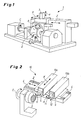
- Fig. 1 is a prior art lathe 1 for producing a complex asymmetrical contour having workpiece, such as in particular a a mit roller 2 (see also Fig. 3 ), represented by turning.
- the workpiece / the mit roller 2 is rotatably clamped about the workpiece axis of rotation C.
- An unrecognizable turning tool is adjustable about a pivot axis A and is moved on the rotating workpiece 2 by means of a tool slide 3 in the direction of the tool main drive axis Z along.
- the turning tool / tool executes the feeding and advancing movement (X-axis) and has a Y-axis necessary for the vertical alignment of the turning tool to the lateral workpiece surface.
- cutting machine 10 shown in detail is designed as a turning and milling machine.
- the about the workpiece axis C rotating workpiece 2 are here on a linear guide 4 two movable in the Z direction and deliverable in the X direction with the feed movement tool carriage 13 a and 13 b assigned.
- the tool carriage 13 a has a tool head 5 carried by a vertical axis of rotation 7 (see Fig. 3 and 4 ) driven side milling cutter 6, which is provided on its outer circumference with evenly distributed arranged round plates 8.
- the tool carriage 13 b has for rotating machining of the workpiece or the mit roller 2 a tool supported by the tool head 9 turning tool 12 with a round plate eleventh
- the horizontally employed or standing turning steel 12 with the round plate 11 is about the pivot axis A (see. Fig. 2 ) adjustable, so that when tilted lateral pivoting is possible.
- the rake angle undergoes no change and remains largely the same.
- the rotationally symmetrical contour regions 15 to be machined by turning are in the FIGS. 4 and 5 illustrated with thick solid lines. These are at a vocational roller 2, the outer circumferential surfaces with transition 15 a to the vocational mouth 16 and its cylindrical contour portion 15 b, ie essentially the smoothing zone to about passing in the deformation zone and the outlet zone as in Fig. 4 indicated by the boundary lines 17 a, 17 b.
- the contour of the workpiece 2 is defined by radii that are variable in angular steps of 10 °, the machining being programmable over the radius of the milling cutter RFR up to the middle of the round plates MRP and the radius of the round plates RRP, as in FIG Fig. 6 schematically registered, which is still an operating point 18 of a round plate 8 of the disc cutter 6 on the asymmetric or non-rotationally symmetrical contour of the workpiece 2 in the processing situation of Fig. 4 can be removed.
Landscapes
- Engineering & Computer Science (AREA)
- Mechanical Engineering (AREA)
- Milling Processes (AREA)
Abstract
Description
- Die Erfindung betrifft ein Verfahren zur spanenden Bearbeitung komplexer Konturen von asymmetrischen Werkstücken, wie Pilgerwalzen, auf einer computergesteuerten Bearbeitungsmaschine sowie eine Bearbeitungsmaschine zum Durchführen des Verfahrens.
- Zum Unrunddrehen, wie insbesondere für die Herstellung von Pilgerwalzen, sind im praktischen Betrieb Warmpilgerwalzendrehmaschinen mit computernumerischer Steuerung im Einsatz. Die bei Pilgerwalzen vorliegende, eine weite Einlassöffnung mit einer erheblichen Verschiebung der Rotationsmasse aus der Drehachse der Walze einschließende exzentrische Form bringt beim Unrunddrehen sich ständig verändernde Span- und Freiwinkel mit sich, wobei durch die Spanwinkelveränderungen die Schnittkräfte erheblich variieren.
- Die in der Praxis bekannten Warmpilgerwalzendrehmaschinen erfordern daher ein Maschinenkonzept mit fünf gesteuerten Achsen, wobei in den Achsen hohe Beschleunigungskräfte der Massen- und Schnittkräfte auftreten. Um die Beschleunigungen, die bereits innerhalb der normalen Kontur oberhalb von 20 m/s2 liegen und zur Reduzierung von Winkelfehlern durch Variation der Höhenlage des Drehstahls insbesondere zur Herstellung des Pilgermauls radial zum Werkstück bzw. in X-Richtung noch deutlich größer sind, zu begrenzen, wird eine geringe Schnittgeschwindigkeit in Kauf genommen. Zudem sind hohe Antriebsleistungen und große Steifigkeiten der Maschine notwendig, damit die gewünschten Oberflächengüten und eine höhere Standzeit der Werkzeuge (Drehstahl) erreichbar sind.
- Der Erfindung liegt daher die Aufgabe zugrunde, ein Verfahren und eine Bearbeitungsmaschine der eingangs genannten Art zu schaffen, mit denen sich komplexe Konturen ohne die geschilderten Nachteile herstellen lassen, wobei gleiche Schnittgeschwindigkeiten, z.B. 200 m/min, des Werkzeugs und geringe Beschleunigungskräfte bei einfacher Auslegung der Maschine möglich sein sollen.
- Diese Aufgabe wird mit einem Verfahren erfindungsgemäß dadurch gelöst, daß das Werkstück durch Drehen und Fräsen mit jeweils Rundplatten als Schneidwerkzeuge auf einer Maschine bearbeitet wird, wobei für die rotationssymmetrischen Konturbereiche des Werkstücks eine Drehbearbeitung und für die asymmetrischen Konturbereiche des Werkstücks eine Fräsbearbeitung durchgeführt wird. Der Erfindung liegt die Erkenntnis zugrunde, dass aufgrund der horizontal mit Rundplatten zum Einsatz kommenden Werkzeuge diese nicht mehr nach oben und unten gefahren werden müssen, so dass eine bei herkömmlichen Drehmaschinen zur senkrechten Ausrichtung des Drehmeißels zur seitlichen Werkstückoberfläche unabdingbare Y-Achse entfallen kann, weil kein Anstellwinkelproblem mehr auftritt. Denn aufgrund der horizontal liegenden Rundplatten erfährt der Spanwinkel keine Änderung und bleibt weitestgehend gleich. Das Drehen kann mit hohen und das Fräsen mit niedrigen Drehzahlen durchgeführt werden.
- Eine bevorzugte Ausführung der Erfindung sieht vor, dass ein an seinem Außenumfang mit Rundplatten bestückter Scheibenfräser und ein mit einer Rundplatte bestückter Drehstahl zur jeweiligen Bearbeitung des Werkstücks mit dem Mittelpunkt der Rundplatten auf einer auf dem Mittelpunkt des Werkstücks liegenden Wirklinie radial (X-Achse) gegen das drehende Werkstück zugestellt und koaxial (Z-Achse) zum Werkstück verfahren wird, wobei die Rotationsachse des angetriebenen Scheibenfräsers rechtwinklig zur Wirklinie verläuft. Der Scheibenfräser kann hierbei mit vertikaler oder horizontaler Rotationsachse auf dem Werkzeugschlitten vorgesehen werden.
- Die hierzu eingesetzte Bearbeitungsmaschine ist erfindungsgemäß dadurch gekennzeichnet, dass ein radial gegen das Werkstück zustellbarer, auf einer Linearführung koaxial zum Werkstück verfahrbarer Werkzeugschlitten einen an seinem Außenumfang mit Rundplatten bestückten, angetriebenen Scheibenfräser aufweist und auf der Linearführung ein radial gegen das drehbare Werkstück zustellbarer Werkzeugschlitten mit einem mit einer Rundplatte bestückten Drehstahl angeordnet ist. Sobald die Drehbearbeitung der bezogen auf den Mittenpunkt bzw. die Mittenachse des Werkstücks rotationssymmetrischen bzw. zylindrischen Konturbereiche beendet ist, wird der Werkzeugschlitten des Scheibenfräsers gegen das Werkstück angestellt, so dass dann die bezogen auf den Mittenpunkt bzw. die Mittenachse des Werkstücks asymmetrischen Konturbereiche gefräst werden. Es lässt sich damit ein Drehen und Fräsen auf einer lediglich noch 4-Achsen-Maschine als Dreh- und Fräsmaschine mit programmierbarer Erfassung der komplexen Werkstück- / Walzenausführungen bzw. -konturen erreichen. Die nur noch geringen Beschleunigungen in den Achsen erlauben berechenbare Kräfte in den Maschinenkomponenten und damit eine sichere sowie kostengünstige Auslegung. Hohe Beschleunigungssprünge werden durch die Fräsbearbeitung der nicht rotationssymmetrischen Konturbereiche vermieden.
- Nach einem Vorschlag der Erfindung wird die Kontur des Werkstücks über in bestimmten Winkelschritten, z.B. 10°, veränderlichen Radien definiert. Hierbei ist von jeder Werkstückkontur eine Dokumentation und Datensicherung möglich. Es ist bevorzugt, dass der Mittelpunkt der Radien auf der Mitte des Werkstücks liegt.
- Weitere Merkmale und Einzelheiten der Erfindung ergeben sich aus den Ansprüchen und aus der Beschreibung eines in den Zeichnungen schematisch mit einer Pilgerwalze als Werkstück dargestellten Ausführungsbeispiels der Erfindung. Es zeigen:
- Fig. 1
- eine perspektivische Gesamtansicht einer herkömmlichen, aus der betrieblichen Praxis zum Stand der Technik zählenden Warmpilgerwalzendrehmaschine mit dazu erforderlichen, fünf gesteuerten Achsen;
- Fig. 2
- in einer prespektivischen Teilansicht das erfindungsgemäße Konzept einer Dreh- und Fräsmaschine, die auf einer Linearführung einen Werkzeugschlitten mit einem Fräskopf und hier vertikaler Rotationsachse für einen mit Rundplatten versehenen Scheibenfräser sowie einen Werkzeugschlitten mit einem mit einer Rundplatte bestückten Drehstahl aufweist;
- Fig. 3
- in einer Vorderansicht als Beispiel für ein eine komplexe Kontur aufweisendes Werkstück eine Pilgerwalze;
- Fig. 4
- eine Pilgenrwalzengeometrie in einem Querschnitt der
Fig. 3 mit auf Mitte des Werkstücks bzw. der Pilgerwalze zur Bearbeitung angestelltem Scheibenfräser; - Fig. 5
- eine Draufsicht der
Fig. 4 , die auch den Werkzeugschlitten mit dem Drehstahl (vgl.Fig. 2 ) erkennen lässt; - Fig. 6
- als Einzelheit in vereinfachter Darstellung als Teilansicht einen Arbeitspunkt einer Rundplatte eines Scheibenfräsers; und
- Fig. 7
- eine Pilgerwalzengeometrie in einem Querschnitt mit Definition der Kontur über in Winkelschritten von 10° veränderlichen Radien.
- In
Fig. 1 ist eine zum Stand der Technik zählende Drehmaschine 1 zum Herstellen eines eine komplexe asymmetrische Kontur aufweisenden Werkstücks, wie insbesondere eine Pilgerwalze 2 (vgl. auchFig. 3 ), durch Drehbearbeitung dargestellt. Das Werkstück / die Pilgerwalze 2 ist um die Werkstückdrehachse C drehend eingespannt. Ein nicht zu erkennender Drehmeißel ist um eine Schwenkachse A verstellbar und wird am drehenden Werkstück 2 mit Hilfe eines Werkzeugschlittens 3 in Richtung der Werkzeug-Hauptantriebsachse Z entlang bewegt. Der Drehmeißel / das Werkzeug führt die Zustell- und Vorschubbewegung (X-Achse) aus und weist eine zur senkrechten Ausrichtung des Drehmeißels zur seitlichen Werkstückoberfläche erforderliche Y-Achse auf. - Die in
Fig. 2 ausschnittsweise dargestellte Bearbeitungsmaschine 10 ist als Dreh- und Fräsmaschine ausgebildet. Dem um die Werkstückdrehachse C rotierenden Werkstück 2 sind hier auf einer Linearführung 4 zwei in Z-Richtung verfahrbare und in X-Richtung mit der Vorschubbewegung zustellbare Werkzeugschlitten 13 a bzw. 13 b zugeordnet. Der Werkzeugschlitten 13 a weist einen vom Werkzeugkopf 5 getragenen, um eine vertikale Rotationsachse 7 (vgl. dieFig. 3 und4 ) angetriebenen Scheibenfräser 6 auf, der an seinem Außenumfang mit gleichmäßig verteilt angeordneten Rundplatten 8 versehen ist. Der Werkzeugschlitten 13 b besitzt zur Drehbearbeitung des Werkstücks bzw. der Pilgerwalze 2 einen vom Werkzeugkopf 9 getragenen Drehstahl 12 mit einer Rundplatte 11. - Zur Bearbeitung des Werkstückrohlings zu dem fertigen Werkstück bzw. zur Pilgerwalze 2 werden der Scheibenfräser 6 - wie für diesen in
Fig. 4 und 6 dargestellt - bzw. der Drehstahl 12 mit dem Mittelpunkt der Rundplatten 8 bzw. der Rundplatte 11 auf einer auf dem Mittelpunkt M des Werkstücks 2 liegenden Wirklinie 14 horizontal an - bzw. zugestellt, wobei die Rotationsachse 7 des angetriebenen Scheibenfräsers 6 rechtwinklig zur Wirklinie 14 verläuft. Der horizontal angestellte bzw. stehende Drehstahl 12 mit der Rundplatte 11 ist um die Schwenkachse A (vgl.Fig. 2 ) verstellbar, so dass bei einer Schrägbearbeitung ein seitliches Schwenken möglich ist. Wie in denFig. 3 und6 angedeutet wird, lassen sich aufgrund der horizontal angestellten bzw. liegenden Rundplatten 8, 11 konstante Winkelverhältnisse erreichen, insbesondere erfährt der Spanwinkel keine Veränderung und bleibt weitestgehend gleich. - Die durch Drehen zu bearbeitenden, rotationssymmetrischen Konturbereiche 15 sind in den
Figuren 4 und 5 mit dick durchgezogenen Linien verdeutlicht. Das sind bei einer Pilgerwalze 2 die Außenmantelflächen mit Übergang 15 a zum Pilgermaul 16 und dessen zylindrischer Konturabschnitt 15 b, d. h. im Wesentlichen die Glättzone bis etwa übergehend in die Verformungszone und die Auslaufzone wie inFig. 4 durch die Begrenzungslinien 17 a, 17 b angedeutet. - Nach
Fig. 7 wird die Kontur des Werkstücks 2 über in Winkelschritten von 10° veränderlichen Radien definiert, wobei die Bearbeitung programmierbar ist über den Radius des Fräsers RFR bis zur Mitte der Rundplatten MRP und dem Radius der Rundplatten RRP, wie inFig. 6 schematisch eingetragen, der sich weiterhin ein Arbeitspunkt 18 einer Rundplatte 8 des Scheibenfräsers 6 an der asymmetrischen bzw. nicht rotationssymmetrischen Kontur des Werkstücks 2 in der Bearbeitungssituation derFig. 4 entnehmen lässt. - Bezugszeichenliste
- 1
- Drehmaschine
- 2
- Werkstück / Pilgerwalze
- 3
- Werkzeugschlitten
- 4
- Linearführung
- 5
- Werkzeugkopf (Fräser)
- 6
- Scheibenfräser
- 7
- Rotationsachse (des Scheibenfräsers)
- 8
- Rundplatte
- 9
- Werkzeugkopf (des Drehstahls)
- 10
- Bearbeitungsmaschine / Dreh- und Fräsmaschine
- 11
- Rundplatte (des Drehstahls)
- 12
- Drehstahl
- 13 a, b
- Werkzeugschlitten
- 14
- Wirklinie
- 15
- rotationssymmetrischer Konturbereich
- 15 a
- Übergangskontur
- 15 b
- zylindrischer Konturabschnitt
- 16
- Pilgermaul
- 17 a, b
- Begrenzungslinien
- 18
- Arbeitspunkt (einer Rundplatte)
- RFR
- Radius des Fräsers
- MRP
- Mitte der Fräser-Rundplatten
- RRP
- Radius der Rundplatten
- A
- Schwenkachse im Werkzeug
- C
- Werkstückdrehachse
- X
- radiale Werkzeug - Zustellachse / Vorschubbewegung
- Y
- vertikale Werkzeug-Ausrichtachse
- Z
- Werkzeug-Hauptantriebsachse
- M
- Mittelpunkt (bzw. Mitte) des Werkstücks
Claims (5)
- Verfahren zur spanenden Bearbeitung komplexer Konturen von asymmetrischen Werkstücken, wie Pilgerwalzen, auf einer computergesteuerten Bearbeitungsmaschine,
dadurch gekennzeichnet,
dass das Werkstück (2) durch Drehen und Fräsen mit jeweils Rundplatten (8; 11) als Schneidwerkzeug auf einer Maschine bearbeitet wird, wobei für die rotationssymmetrischen Konturbereiche (15) des Werkstücks (2) eine Drehbearbeitung und für die asymmetrischen Konturbereiche des Werkstücks (2) eine Fräsbearbeitung vorgenommen wird. - Verfahren nach Anspruch 1,
dadurch gekennzeichnet,
daß ein an seinem Außenumfang mit Rundplatten (8) bestückter Scheibenfräser (6) und ein mit einer Rundplatte (11) bestückter Drehstahl (12) zur jeweiligen Bearbeitung des Werkstücks (2) mit dem Mittelpunkt der Rundplatten (8) auf einer auf dem Mittelpunkt (M) des Werkstücks (2) liegenden Wirklinie (14) radial (X-Achse) gegen das drehende Werkstück zugestellt und koaxial (Z-Achse) zum Werkstück verfahren wird, wobei die Rotationsachse (7) des angetriebenen Scheibenfräsers (6) rechtwinklig zur Wirklinie (14) verläuft. - Verfahren nach Anspruch 1 oder 2,
dadurch gekennzeichnet,
dass die Kontur des Werkstücks (2) über in bestimmten Winkelschritten, z.B. 10°, veränderlichen Radien (RO bis R35) definiert wird. - Verfahren nach Anspruch 3,
dadurch gekennzeichnet,
dass der Mittelpunkt der Radien (RO bis R35) auf der Mitte (M) des Werkstücks (2) liegt. - Computergesteuerte Bearbeitungsmaschine zur spanenden Bearbeitung komplexer Konturen von asymmetrischen Werkstücken, wie Pilgerwalzen, insbesondere zum Durchführen des Verfahrens nach Anspruch 1,
dadurch gekennzeichnet,
dass ein radial (X-Achse) gegen das Werkstück (2) zustellbarer, auf einer Linearführung (4) koaxial (Z-Achse) zum Werkstück verfahrbarer Werkzeugschlitten (13 a) einen an seinem Außenumfang mit Rundplatten (8) bestückten, angetriebenen Scheibenfräser aufweist und auf der Linearführung (4) ein radial (X-Achse) gegen das drehende Werkstück (2) zustellbarer Werkzeugschlitten (13 b) mit einem mit einer Rundplatte (11) bestückten Drehstahl (12) angeordnet ist.
Applications Claiming Priority (2)
| Application Number | Priority Date | Filing Date | Title |
|---|---|---|---|
| DE102008008269 | 2008-02-08 | ||
| DE102009004964A DE102009004964A1 (de) | 2008-02-08 | 2009-01-14 | Verfahren und Bearbeitungsmaschine zur spanenden Bearbeitung komplexer Konturen von asymmetrischen Werkstücken |
Publications (2)
| Publication Number | Publication Date |
|---|---|
| EP2087956A1 true EP2087956A1 (de) | 2009-08-12 |
| EP2087956B1 EP2087956B1 (de) | 2013-09-04 |
Family
ID=40688434
Family Applications (1)
| Application Number | Title | Priority Date | Filing Date |
|---|---|---|---|
| EP20090001478 Not-in-force EP2087956B1 (de) | 2008-02-08 | 2009-02-04 | Verfahren und Bearbeitungsmaschine zur spanenden Bearbeitung komplexer Konturen von asymmetrischen Werkstücken |
Country Status (1)
| Country | Link |
|---|---|
| EP (1) | EP2087956B1 (de) |
Cited By (7)
| Publication number | Priority date | Publication date | Assignee | Title |
|---|---|---|---|---|
| CN102736556A (zh) * | 2012-06-13 | 2012-10-17 | 深圳众为兴技术股份有限公司 | 一种非圆切削加工控制装置及控制方法 |
| WO2014130886A2 (en) | 2013-02-21 | 2014-08-28 | Chromatic Industries, Inc. | Double offset ball member usable in ball valves and other flow control applications |
| CN104690347A (zh) * | 2013-12-04 | 2015-06-10 | 宁安市粮油淀粉机械制造有限公司 | 锉磨机转子加工用数控铣床 |
| CN107737979A (zh) * | 2017-11-22 | 2018-02-27 | 南通精育机械有限公司 | 数控轧辊槽加工机床及其加工方法 |
| US20210046551A1 (en) * | 2018-03-08 | 2021-02-18 | Ab Sandvik Coromant | Turning method for a cnc-lathe and a turning tool |
| CN116748538A (zh) * | 2023-07-25 | 2023-09-15 | 广东亚数智能科技股份有限公司 | 操作便捷的车床用工件圆弧加工装置 |
| CN120421569A (zh) * | 2025-05-29 | 2025-08-05 | 唐山永丰轧辊有限公司 | 一种异形轧辊生产用成型装置及加工方法 |
Citations (4)
| Publication number | Priority date | Publication date | Assignee | Title |
|---|---|---|---|---|
| DE4026898C1 (de) | 1990-08-23 | 1991-05-02 | Mannesmann Ag, 4000 Duesseldorf, De | |
| EP0882548A2 (de) | 1997-06-06 | 1998-12-09 | NILES-SIMMONS Industrieanlagen GmbH | CNC Dreh- und Fräsbearbeitungszentrum |
| EP1413395A1 (de) * | 2002-10-24 | 2004-04-28 | Emag Maschinenfabrik Gmbh | Werkzeugmaschine |
| WO2005080048A1 (de) * | 2004-02-25 | 2005-09-01 | Fritz Studer Ag | Bearbeitungsmaschine zum bearbeiten von werkstücken |
-
2009
- 2009-02-04 EP EP20090001478 patent/EP2087956B1/de not_active Not-in-force
Patent Citations (4)
| Publication number | Priority date | Publication date | Assignee | Title |
|---|---|---|---|---|
| DE4026898C1 (de) | 1990-08-23 | 1991-05-02 | Mannesmann Ag, 4000 Duesseldorf, De | |
| EP0882548A2 (de) | 1997-06-06 | 1998-12-09 | NILES-SIMMONS Industrieanlagen GmbH | CNC Dreh- und Fräsbearbeitungszentrum |
| EP1413395A1 (de) * | 2002-10-24 | 2004-04-28 | Emag Maschinenfabrik Gmbh | Werkzeugmaschine |
| WO2005080048A1 (de) * | 2004-02-25 | 2005-09-01 | Fritz Studer Ag | Bearbeitungsmaschine zum bearbeiten von werkstücken |
Cited By (10)
| Publication number | Priority date | Publication date | Assignee | Title |
|---|---|---|---|---|
| CN102736556A (zh) * | 2012-06-13 | 2012-10-17 | 深圳众为兴技术股份有限公司 | 一种非圆切削加工控制装置及控制方法 |
| WO2014130886A2 (en) | 2013-02-21 | 2014-08-28 | Chromatic Industries, Inc. | Double offset ball member usable in ball valves and other flow control applications |
| EP2959196A4 (de) * | 2013-02-21 | 2016-10-26 | Chromatic Ind Inc | Kugelelement mit doppeltem versatz für kugelventile und andere flusssteuerungsanwendungen |
| CN104690347A (zh) * | 2013-12-04 | 2015-06-10 | 宁安市粮油淀粉机械制造有限公司 | 锉磨机转子加工用数控铣床 |
| CN107737979A (zh) * | 2017-11-22 | 2018-02-27 | 南通精育机械有限公司 | 数控轧辊槽加工机床及其加工方法 |
| US20210046551A1 (en) * | 2018-03-08 | 2021-02-18 | Ab Sandvik Coromant | Turning method for a cnc-lathe and a turning tool |
| US12172218B2 (en) * | 2018-03-08 | 2024-12-24 | Ab Sandvik Coromant | Turning method for a CNC-lathe and a turning tool |
| CN116748538A (zh) * | 2023-07-25 | 2023-09-15 | 广东亚数智能科技股份有限公司 | 操作便捷的车床用工件圆弧加工装置 |
| CN116748538B (zh) * | 2023-07-25 | 2024-01-09 | 广东亚数智能科技股份有限公司 | 操作便捷的车床用工件圆弧加工装置 |
| CN120421569A (zh) * | 2025-05-29 | 2025-08-05 | 唐山永丰轧辊有限公司 | 一种异形轧辊生产用成型装置及加工方法 |
Also Published As
| Publication number | Publication date |
|---|---|
| EP2087956B1 (de) | 2013-09-04 |
Similar Documents
| Publication | Publication Date | Title |
|---|---|---|
| DE102009004964A1 (de) | Verfahren und Bearbeitungsmaschine zur spanenden Bearbeitung komplexer Konturen von asymmetrischen Werkstücken | |
| EP2823924B1 (de) | Doppelabrichter | |
| EP1719585B1 (de) | Maschine zur Bearbeitung von optischen Werkstücken, namentlich Kunststoff-Brillengläsern | |
| EP2007548B1 (de) | Verfahren zur schleifbearbeitung eines maschinenbauteils und schleifmaschine zur durchführung des verfahrens | |
| EP3463746B1 (de) | Maschine zur bearbeitung von optisch wirksamen flächen | |
| DE102009059897B4 (de) | Verfahren zum Rundschleifen von langen, dünnen Rundstangen und Rundschleifmaschine zur Durchführung des Verfahrens | |
| EP2167277B1 (de) | Schleifzentrum und verfahren zum gleichzeitigen schleifen mehrerer lager und endseitigen flächen von kurbelwellen | |
| EP2087956B1 (de) | Verfahren und Bearbeitungsmaschine zur spanenden Bearbeitung komplexer Konturen von asymmetrischen Werkstücken | |
| DE10256222B4 (de) | Maschine und Verfahren mit 7 Achsen zum CNC-gesteuerten spanabhebenden Bearbeiten, insbesondere Wälzfräsen oder Wälzschleifen, von Spiralkegelrädern | |
| EP2762254B1 (de) | Kurbelwellendreh- und Fräsmaschine | |
| EP1427568A1 (de) | Verfahren und vorrichtung zum schleifen von zentrischen lagerstellen von kurbelwellen | |
| DE2658970C3 (de) | Kurbelwellenfräsmaschine | |
| WO2013174487A2 (de) | Vorrichtung und verfahren zur bearbeitung eines optischen werkstücks | |
| EP1824627B1 (de) | Verfahren und Werkzeugmaschine zum Bearbeiten der Lagersitze von Wellen | |
| DE102007033767B4 (de) | Verfahren und Vorrichtung zur Bearbeitung von Werkstückoberflächen | |
| DE102006014972B4 (de) | Kombiniertes Bearbeitungsverfahren und Bearbeitungseinrichtung | |
| EP0885082B1 (de) | Verfahren und vorrichtung zum bearbeiten der lagersitze von kurbelwellen | |
| DE2044429A1 (de) | Vorrichtung zur Bearbeitung von kugelförmigen Innenflachen, die auf einem vertikalen Trager angeordnet ist | |
| DE102012004902B4 (de) | Verfahren und Vorrichtung zur spanabhebenden Bearbeitung von Werkstücken | |
| EP1722912B1 (de) | Verfahren zur herstellung von profilbahnen für gelenkteile | |
| DE10245071A1 (de) | Maschine zum Schruppen und Schlichten der Lagerzapfen von Kurbelwellen | |
| DE2217288C3 (de) | Einrichtung an einer Drehmaschine zum Herstellen von Nuten an drehsymmetrischen Werkstücken | |
| DE933123C (de) | Verfahren zum Bearbeiten von drei- und mehrfluegeligen Propellernabenkoerpern | |
| EP3330026B1 (de) | Drehräumwerkzeug | |
| AT138300B (de) | Verfahren und Vorrichtung zur Bearbeitung von Walzen, insbesondere von Kaliberwalzen für Pilgerschrittwalzwerke, sowie Walzenkaliber. |
Legal Events
| Date | Code | Title | Description |
|---|---|---|---|
| PUAI | Public reference made under article 153(3) epc to a published international application that has entered the european phase |
Free format text: ORIGINAL CODE: 0009012 |
|
| AK | Designated contracting states |
Kind code of ref document: A1 Designated state(s): AT BE BG CH CY CZ DE DK EE ES FI FR GB GR HR HU IE IS IT LI LT LU LV MC MK MT NL NO PL PT RO SE SI SK TR |
|
| AX | Request for extension of the european patent |
Extension state: AL BA RS |
|
| 17P | Request for examination filed |
Effective date: 20100112 |
|
| 17Q | First examination report despatched |
Effective date: 20100212 |
|
| AKX | Designation fees paid |
Designated state(s): AT BE BG CH CY CZ DE DK EE ES FI FR GB GR HR HU IE IS IT LI LT LU LV MC MK MT NL NO PL PT RO SE SI SK TR |
|
| GRAP | Despatch of communication of intention to grant a patent |
Free format text: ORIGINAL CODE: EPIDOSNIGR1 |
|
| INTG | Intention to grant announced |
Effective date: 20130403 |
|
| GRAS | Grant fee paid |
Free format text: ORIGINAL CODE: EPIDOSNIGR3 |
|
| GRAA | (expected) grant |
Free format text: ORIGINAL CODE: 0009210 |
|
| AK | Designated contracting states |
Kind code of ref document: B1 Designated state(s): AT BE BG CH CY CZ DE DK EE ES FI FR GB GR HR HU IE IS IT LI LT LU LV MC MK MT NL NO PL PT RO SE SI SK TR |
|
| REG | Reference to a national code |
Ref country code: GB Ref legal event code: FG4D Free format text: NOT ENGLISH |
|
| REG | Reference to a national code |
Ref country code: CH Ref legal event code: EP |
|
| REG | Reference to a national code |
Ref country code: AT Ref legal event code: REF Ref document number: 630202 Country of ref document: AT Kind code of ref document: T Effective date: 20130915 |
|
| REG | Reference to a national code |
Ref country code: IE Ref legal event code: FG4D Free format text: LANGUAGE OF EP DOCUMENT: GERMAN |
|
| REG | Reference to a national code |
Ref country code: DE Ref legal event code: R096 Ref document number: 502009007921 Country of ref document: DE Effective date: 20131031 |
|
| REG | Reference to a national code |
Ref country code: NL Ref legal event code: VDEP Effective date: 20130904 |
|
| PG25 | Lapsed in a contracting state [announced via postgrant information from national office to epo] |
Ref country code: SE Free format text: LAPSE BECAUSE OF FAILURE TO SUBMIT A TRANSLATION OF THE DESCRIPTION OR TO PAY THE FEE WITHIN THE PRESCRIBED TIME-LIMIT Effective date: 20130904 Ref country code: CY Free format text: LAPSE BECAUSE OF FAILURE TO SUBMIT A TRANSLATION OF THE DESCRIPTION OR TO PAY THE FEE WITHIN THE PRESCRIBED TIME-LIMIT Effective date: 20130807 Ref country code: NO Free format text: LAPSE BECAUSE OF FAILURE TO SUBMIT A TRANSLATION OF THE DESCRIPTION OR TO PAY THE FEE WITHIN THE PRESCRIBED TIME-LIMIT Effective date: 20131204 Ref country code: HR Free format text: LAPSE BECAUSE OF FAILURE TO SUBMIT A TRANSLATION OF THE DESCRIPTION OR TO PAY THE FEE WITHIN THE PRESCRIBED TIME-LIMIT Effective date: 20130904 Ref country code: LT Free format text: LAPSE BECAUSE OF FAILURE TO SUBMIT A TRANSLATION OF THE DESCRIPTION OR TO PAY THE FEE WITHIN THE PRESCRIBED TIME-LIMIT Effective date: 20130904 |
|
| REG | Reference to a national code |
Ref country code: NL Ref legal event code: VDEP Effective date: 20130904 |
|
| REG | Reference to a national code |
Ref country code: LT Ref legal event code: MG4D |
|
| PG25 | Lapsed in a contracting state [announced via postgrant information from national office to epo] |
Ref country code: SI Free format text: LAPSE BECAUSE OF FAILURE TO SUBMIT A TRANSLATION OF THE DESCRIPTION OR TO PAY THE FEE WITHIN THE PRESCRIBED TIME-LIMIT Effective date: 20130904 Ref country code: FI Free format text: LAPSE BECAUSE OF FAILURE TO SUBMIT A TRANSLATION OF THE DESCRIPTION OR TO PAY THE FEE WITHIN THE PRESCRIBED TIME-LIMIT Effective date: 20130904 Ref country code: PL Free format text: LAPSE BECAUSE OF FAILURE TO SUBMIT A TRANSLATION OF THE DESCRIPTION OR TO PAY THE FEE WITHIN THE PRESCRIBED TIME-LIMIT Effective date: 20130904 Ref country code: LV Free format text: LAPSE BECAUSE OF FAILURE TO SUBMIT A TRANSLATION OF THE DESCRIPTION OR TO PAY THE FEE WITHIN THE PRESCRIBED TIME-LIMIT Effective date: 20130904 Ref country code: GR Free format text: LAPSE BECAUSE OF FAILURE TO SUBMIT A TRANSLATION OF THE DESCRIPTION OR TO PAY THE FEE WITHIN THE PRESCRIBED TIME-LIMIT Effective date: 20131205 |
|
| PG25 | Lapsed in a contracting state [announced via postgrant information from national office to epo] |
Ref country code: CY Free format text: LAPSE BECAUSE OF FAILURE TO SUBMIT A TRANSLATION OF THE DESCRIPTION OR TO PAY THE FEE WITHIN THE PRESCRIBED TIME-LIMIT Effective date: 20130904 |
|
| PG25 | Lapsed in a contracting state [announced via postgrant information from national office to epo] |
Ref country code: SK Free format text: LAPSE BECAUSE OF FAILURE TO SUBMIT A TRANSLATION OF THE DESCRIPTION OR TO PAY THE FEE WITHIN THE PRESCRIBED TIME-LIMIT Effective date: 20130904 Ref country code: CZ Free format text: LAPSE BECAUSE OF FAILURE TO SUBMIT A TRANSLATION OF THE DESCRIPTION OR TO PAY THE FEE WITHIN THE PRESCRIBED TIME-LIMIT Effective date: 20130904 Ref country code: EE Free format text: LAPSE BECAUSE OF FAILURE TO SUBMIT A TRANSLATION OF THE DESCRIPTION OR TO PAY THE FEE WITHIN THE PRESCRIBED TIME-LIMIT Effective date: 20130904 Ref country code: IS Free format text: LAPSE BECAUSE OF FAILURE TO SUBMIT A TRANSLATION OF THE DESCRIPTION OR TO PAY THE FEE WITHIN THE PRESCRIBED TIME-LIMIT Effective date: 20140104 Ref country code: RO Free format text: LAPSE BECAUSE OF FAILURE TO SUBMIT A TRANSLATION OF THE DESCRIPTION OR TO PAY THE FEE WITHIN THE PRESCRIBED TIME-LIMIT Effective date: 20130904 Ref country code: NL Free format text: LAPSE BECAUSE OF FAILURE TO SUBMIT A TRANSLATION OF THE DESCRIPTION OR TO PAY THE FEE WITHIN THE PRESCRIBED TIME-LIMIT Effective date: 20130904 |
|
| PGFP | Annual fee paid to national office [announced via postgrant information from national office to epo] |
Ref country code: DE Payment date: 20140219 Year of fee payment: 6 |
|
| PG25 | Lapsed in a contracting state [announced via postgrant information from national office to epo] |
Ref country code: ES Free format text: LAPSE BECAUSE OF FAILURE TO SUBMIT A TRANSLATION OF THE DESCRIPTION OR TO PAY THE FEE WITHIN THE PRESCRIBED TIME-LIMIT Effective date: 20130904 |
|
| PGFP | Annual fee paid to national office [announced via postgrant information from national office to epo] |
Ref country code: IT Payment date: 20140221 Year of fee payment: 6 |
|
| REG | Reference to a national code |
Ref country code: DE Ref legal event code: R097 Ref document number: 502009007921 Country of ref document: DE |
|
| PG25 | Lapsed in a contracting state [announced via postgrant information from national office to epo] |
Ref country code: PT Free format text: LAPSE BECAUSE OF FAILURE TO SUBMIT A TRANSLATION OF THE DESCRIPTION OR TO PAY THE FEE WITHIN THE PRESCRIBED TIME-LIMIT Effective date: 20140106 |
|
| PLBE | No opposition filed within time limit |
Free format text: ORIGINAL CODE: 0009261 |
|
| STAA | Information on the status of an ep patent application or granted ep patent |
Free format text: STATUS: NO OPPOSITION FILED WITHIN TIME LIMIT |
|
| 26N | No opposition filed |
Effective date: 20140605 |
|
| BERE | Be: lapsed |
Owner name: SMS MEER G.M.B.H. Effective date: 20140228 |
|
| REG | Reference to a national code |
Ref country code: DE Ref legal event code: R097 Ref document number: 502009007921 Country of ref document: DE Effective date: 20140605 |
|
| PG25 | Lapsed in a contracting state [announced via postgrant information from national office to epo] |
Ref country code: DK Free format text: LAPSE BECAUSE OF FAILURE TO SUBMIT A TRANSLATION OF THE DESCRIPTION OR TO PAY THE FEE WITHIN THE PRESCRIBED TIME-LIMIT Effective date: 20130904 Ref country code: LU Free format text: LAPSE BECAUSE OF FAILURE TO SUBMIT A TRANSLATION OF THE DESCRIPTION OR TO PAY THE FEE WITHIN THE PRESCRIBED TIME-LIMIT Effective date: 20140204 Ref country code: MC Free format text: LAPSE BECAUSE OF FAILURE TO SUBMIT A TRANSLATION OF THE DESCRIPTION OR TO PAY THE FEE WITHIN THE PRESCRIBED TIME-LIMIT Effective date: 20130904 |
|
| REG | Reference to a national code |
Ref country code: CH Ref legal event code: PL |
|
| GBPC | Gb: european patent ceased through non-payment of renewal fee |
Effective date: 20140204 |
|
| PG25 | Lapsed in a contracting state [announced via postgrant information from national office to epo] |
Ref country code: LI Free format text: LAPSE BECAUSE OF NON-PAYMENT OF DUE FEES Effective date: 20140228 Ref country code: CH Free format text: LAPSE BECAUSE OF NON-PAYMENT OF DUE FEES Effective date: 20140228 |
|
| REG | Reference to a national code |
Ref country code: FR Ref legal event code: ST Effective date: 20141031 |
|
| REG | Reference to a national code |
Ref country code: IE Ref legal event code: MM4A |
|
| PG25 | Lapsed in a contracting state [announced via postgrant information from national office to epo] |
Ref country code: GB Free format text: LAPSE BECAUSE OF NON-PAYMENT OF DUE FEES Effective date: 20140204 Ref country code: IE Free format text: LAPSE BECAUSE OF NON-PAYMENT OF DUE FEES Effective date: 20140204 Ref country code: BE Free format text: LAPSE BECAUSE OF NON-PAYMENT OF DUE FEES Effective date: 20140228 Ref country code: FR Free format text: LAPSE BECAUSE OF NON-PAYMENT OF DUE FEES Effective date: 20140228 |
|
| REG | Reference to a national code |
Ref country code: AT Ref legal event code: MM01 Ref document number: 630202 Country of ref document: AT Kind code of ref document: T Effective date: 20140204 |
|
| PG25 | Lapsed in a contracting state [announced via postgrant information from national office to epo] |
Ref country code: AT Free format text: LAPSE BECAUSE OF NON-PAYMENT OF DUE FEES Effective date: 20140204 |
|
| REG | Reference to a national code |
Ref country code: DE Ref legal event code: R119 Ref document number: 502009007921 Country of ref document: DE |
|
| PG25 | Lapsed in a contracting state [announced via postgrant information from national office to epo] |
Ref country code: IT Free format text: LAPSE BECAUSE OF NON-PAYMENT OF DUE FEES Effective date: 20150204 |
|
| PG25 | Lapsed in a contracting state [announced via postgrant information from national office to epo] |
Ref country code: DE Free format text: LAPSE BECAUSE OF NON-PAYMENT OF DUE FEES Effective date: 20150901 |
|
| PG25 | Lapsed in a contracting state [announced via postgrant information from national office to epo] |
Ref country code: MT Free format text: LAPSE BECAUSE OF FAILURE TO SUBMIT A TRANSLATION OF THE DESCRIPTION OR TO PAY THE FEE WITHIN THE PRESCRIBED TIME-LIMIT Effective date: 20130904 |
|
| PG25 | Lapsed in a contracting state [announced via postgrant information from national office to epo] |
Ref country code: BG Free format text: LAPSE BECAUSE OF FAILURE TO SUBMIT A TRANSLATION OF THE DESCRIPTION OR TO PAY THE FEE WITHIN THE PRESCRIBED TIME-LIMIT Effective date: 20130904 |
|
| PG25 | Lapsed in a contracting state [announced via postgrant information from national office to epo] |
Ref country code: HU Free format text: LAPSE BECAUSE OF FAILURE TO SUBMIT A TRANSLATION OF THE DESCRIPTION OR TO PAY THE FEE WITHIN THE PRESCRIBED TIME-LIMIT; INVALID AB INITIO Effective date: 20090204 Ref country code: TR Free format text: LAPSE BECAUSE OF FAILURE TO SUBMIT A TRANSLATION OF THE DESCRIPTION OR TO PAY THE FEE WITHIN THE PRESCRIBED TIME-LIMIT Effective date: 20130904 |
|
| PG25 | Lapsed in a contracting state [announced via postgrant information from national office to epo] |
Ref country code: MK Free format text: LAPSE BECAUSE OF FAILURE TO SUBMIT A TRANSLATION OF THE DESCRIPTION OR TO PAY THE FEE WITHIN THE PRESCRIBED TIME-LIMIT Effective date: 20130904 |