EP2087964A2 - Schwingsaugnapf, insbesondere für Maschinentische von Maschinenwerkzeugen - Google Patents
Schwingsaugnapf, insbesondere für Maschinentische von Maschinenwerkzeugen Download PDFInfo
- Publication number
- EP2087964A2 EP2087964A2 EP09425045A EP09425045A EP2087964A2 EP 2087964 A2 EP2087964 A2 EP 2087964A2 EP 09425045 A EP09425045 A EP 09425045A EP 09425045 A EP09425045 A EP 09425045A EP 2087964 A2 EP2087964 A2 EP 2087964A2
- Authority
- EP
- European Patent Office
- Prior art keywords
- suction cup
- cap
- equipment according
- spherical head
- movable
- Prior art date
- Legal status (The legal status is an assumption and is not a legal conclusion. Google has not performed a legal analysis and makes no representation as to the accuracy of the status listed.)
- Withdrawn
Links
Images


Classifications
-
- B—PERFORMING OPERATIONS; TRANSPORTING
- B23—MACHINE TOOLS; METAL-WORKING NOT OTHERWISE PROVIDED FOR
- B23Q—DETAILS, COMPONENTS, OR ACCESSORIES FOR MACHINE TOOLS, e.g. ARRANGEMENTS FOR COPYING OR CONTROLLING; MACHINE TOOLS IN GENERAL CHARACTERISED BY THE CONSTRUCTION OF PARTICULAR DETAILS OR COMPONENTS; COMBINATIONS OR ASSOCIATIONS OF METAL-WORKING MACHINES, NOT DIRECTED TO A PARTICULAR RESULT
- B23Q1/00—Members which are comprised in the general build-up of a form of machine, particularly relatively large fixed members
- B23Q1/03—Stationary work or tool supports
- B23Q1/035—Stationary work or tool supports with an array of longitudinally movable rods defining a reconfigurable support surface
-
- B—PERFORMING OPERATIONS; TRANSPORTING
- B25—HAND TOOLS; PORTABLE POWER-DRIVEN TOOLS; MANIPULATORS
- B25B—TOOLS OR BENCH DEVICES NOT OTHERWISE PROVIDED FOR, FOR FASTENING, CONNECTING, DISENGAGING, OR HOLDING
- B25B11/00—Work holders not covered by any preceding group in the subclass, e.g. magnetic work holders, vacuum work holders
- B25B11/005—Vacuum work holders
-
- B—PERFORMING OPERATIONS; TRANSPORTING
- B23—MACHINE TOOLS; METAL-WORKING NOT OTHERWISE PROVIDED FOR
- B23Q—DETAILS, COMPONENTS, OR ACCESSORIES FOR MACHINE TOOLS, e.g. ARRANGEMENTS FOR COPYING OR CONTROLLING; MACHINE TOOLS IN GENERAL CHARACTERISED BY THE CONSTRUCTION OF PARTICULAR DETAILS OR COMPONENTS; COMBINATIONS OR ASSOCIATIONS OF METAL-WORKING MACHINES, NOT DIRECTED TO A PARTICULAR RESULT
- B23Q2230/00—Special operations in a machine tool
- B23Q2230/002—Using the spindle for performing a non machining or non measuring operation, e.g. cleaning, actuating a mechanism
Definitions
- This invention concerns in general a device for the support and retention of elements to be machined on the worktables of machine tools, and refers, in particular, to a suction cup which can be oriented and is useable in plurality with others, to form a rest top with a variable configuration depending on the shape of the elements to be supported and blocked while being machined by numerical controlled machine tools.
- the worktable is provided with a number of retentions in the form of suction cups connected to a suction group, and from time to time, the item to be machined is supported and retained by said suction cups.
- the items to be machined can be made of a composite material, wood, glass, marble or the like and even of considerable size.
- suction cups in this case are positioned coplanar and activated in number and positioned depending on the dimensions and shape of the item.
- One object of this invention is to meet efficiently the above mentioned problems and to provide correspondingly a vacuum retention system, that is with suction cups, to be used on machine tool worktables, varyingly oriented to define each time a work and blocking top for any element or item to be supported, not only flat, but also with any uniform or variable curvature.
- Another object of the invention is to propose a fixture for the above mentioned use, which can be defined as universal, which can easily be adapted to meet the curved shapes of each element or item and the different dimensions that may exist from item to item of a same model.
- a fixture to support and block elements to be machined using machine tools comprising a number of suction cups assembled on a worktable, connected to a suction group, movable and variable in height, where each suction cup is attached to a support cover, connected to a spherical head and movable in all directions between a horizontal and a sloping position with regard to a vertical axis, and where a control device to establish and define the horizontal position of the cover movable in all directions between a horizontal and a sloping position with regard to the vertical axis, and where the cover is associated with a control device to establish and define the horizontal position of the suction cup and a pulling device to vary the tilt of the suction cup in reply to the application of a force from outside.
- the suction cups positioned on a worktable are each supported by a ball-and-socket joint positioned at the top of the stem of a cylinder placed vertically designed to vary and stabilize the position in height and are individually oriented in all directions so as to form together, a face corresponding to the shape of the item to be supported and to block in the machine.
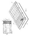
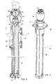
- Figs. 1 and 2 of said drawings is represented, for example, a worktable 11 for tool machines, provided with a number of seats 12 to receive an equivalent number of suction cups 13, destined to pneumatically support and block on the work table every item while it is being machined. Every suction cup is provided with a respective vertical X axis positioning the actuator group 14, as shown in Figs. 3 e 4 .
- the suction cup 13 is applied to a ball-and-socket joint 15 positioned at the top of the actuator 14, and this comprises a primary pneumatic cylinder 16 and an additional control device 17 to establish and define the horizontal position of the suction cup.
- the primary pneumatic cylinder 16 is fixed to the table by means of a support 18 and has a stem 19 at the top of which is applied the ball-and-socket joint 15 which is inserted in a possible extension 20.
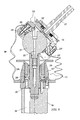
- the ball-and-socket joint 15 is made up of a spherical head 21 fixed to said extension 20 and by a cap 23 to which the suction cup 13 is fixed.
- the vacuum to the suction cup 13 each time it is activated is applied through a duct 22 that is connected externally, by means of a connector, to a suction device, not shown, that extends in the spherical head of the articulated joint 21 and which communicates with the suction cup through some holes 22' provided in the upper shell of the cap 23.
- the cap 23 comprises two complementary shells, one lower 23' and one upper 23", which can be brought together to be blocked on the spherical head 21 and moved apart to enable the orientation of the cap 23, and that of the suction cup 13, with regard to the vertical X axis in all directions starting from its horizontal position.
- the two shells 23' and 23" are configured between them to define a fluid chamber 24. They are connected and normally kept in the blocked position attached to the spherical head 21 by means of springs 25 guided along the stem of a pin 25'. Their separation to be released from the spherical head 21 is caused by the delivery of air under pressure through a connector duct 26 in said chamber 24 creating a force opposed to that of the springs 25. Only then can the cap be moved and turned with regard to the spherical head for the orientation of the suction cup according to needs. The movement and positioning of the cap 23, consequently of the suction cup 13, can be carried out by applying an external force by means of a pulling device 27 set up to engage with the upper shell of the cap ( Fig.
- each of the suction cups 13 on the worktable so that they are positioned differently in height and oriented to define overall a surface that corresponds each time to the shape of the item to be machined.
- the additional control device 17 consists in a secondary pneumatic cylinder 17' fixed to the stem 19 of the primary pneumatic cylinder 16 and is on a level with the extension 20.
- Said pneumatic cylinder 17' therefore follows the movements in height of said stem 19 and forms, with the external surface of the extension 20, an annular chamber 28 in which the piston 29 slides carrying a thrust plate 30 movable in height and designed to insert into the cap, and with it the suction cup, in a horizontal position after each angular orientation.
- the cylinder and the cap are retracted into an inactive position ( Fig. 6 ).
- the piston 29 of the secondary cylinder 17' is activated by feeding air under pressure to the annular chamber 28 so as to move the thrust plate 30 which moves from the bottom towards the top to engage the lowest portion of the lower shell 23' of the cap 23.
- the device has also at least one conduit 31 to deliver air to the primary cylinder 16, one conduit 32 to deliver air to the secondary cylinder 17 which can extend in the stem 19 of the main cylinder 16 and an air feed conduit 33 to the chamber 24 provided between the two shells 23', 23".
- the additional control device 17 for the return of the suction cup 13 in into the horizontal position after each of its tilts consists in a thrust plate 130 fixed to a bush 131, facing towards the joint 15.
- the bush 131 is mounted and slides along the upper part of the stem 19 of the primary pneumatic actuator 14 and is designed to rest with its base on a fixed locator means 132. Between the stem 19 and the bush 131 a chamber or hollow space 133 is provided connected at least to a vent 134. In this case the bush 131, and with it the thrust plate 130, follow the extraction movement of the stem 19 without however interfering with the joint 15 during the positioning in height of the suction cup and its angle.
- the horizontal repositioning of the suction cup takes place on the other hand using a re-entry stroke, that is a return of the stem 19 of the primary actuator14 and as soon as the bush 131 rests against the fixed locator 132. So the bush and plate remain stopped at a height, whereas with a further return stroke of the stem, the joint lowers to rest on the thrust plate 130 with the lowest portion of its lower shell I 23', causing it to turn until the horizontal position is restored.
- a re-entry stroke that is a return of the stem 19 of the primary actuator14 and as soon as the bush 131 rests against the fixed locator 132. So the bush and plate remain stopped at a height, whereas with a further return stroke of the stem, the joint lowers to rest on the thrust plate 130 with the lowest portion of its lower shell I 23', causing it to turn until the horizontal position is restored.
- the ball-and-socket joint 15 and the secondary piston 17 can be contained in a protective casing 34 made of a flexible material.
Landscapes
- Engineering & Computer Science (AREA)
- Mechanical Engineering (AREA)
- Manipulator (AREA)
Applications Claiming Priority (1)
| Application Number | Priority Date | Filing Date | Title |
|---|---|---|---|
| ITBS20080028 ITBS20080028A1 (it) | 2008-02-11 | 2008-02-11 | Ventosa orientabile, particolarmente per tavole portapezzi di macchine operatrici |
Publications (2)
| Publication Number | Publication Date |
|---|---|
| EP2087964A2 true EP2087964A2 (de) | 2009-08-12 |
| EP2087964A3 EP2087964A3 (de) | 2009-10-14 |
Family
ID=40291474
Family Applications (1)
| Application Number | Title | Priority Date | Filing Date |
|---|---|---|---|
| EP09425045A Withdrawn EP2087964A3 (de) | 2008-02-11 | 2009-02-10 | Schwingsaugnapf, insbesondere für Maschinentische von Maschinenwerkzeugen |
Country Status (2)
| Country | Link |
|---|---|
| EP (1) | EP2087964A3 (de) |
| IT (1) | ITBS20080028A1 (de) |
Cited By (3)
| Publication number | Priority date | Publication date | Assignee | Title |
|---|---|---|---|---|
| CN102501100A (zh) * | 2011-11-02 | 2012-06-20 | 江苏申模数字化制造技术有限公司 | 一种真空吸附夹具 |
| KR101882231B1 (ko) * | 2017-02-21 | 2018-07-26 | 중앙대학교 산학협력단 | 자유곡면을 가진 판형 공작물 고정용 엔드 이펙터 |
| CN115157154A (zh) * | 2022-08-25 | 2022-10-11 | 洛阳毅航耐火材料有限公司 | 一种防火材料真空吸附加工装备 |
Family Cites Families (4)
| Publication number | Priority date | Publication date | Assignee | Title |
|---|---|---|---|---|
| US5590870A (en) * | 1995-06-02 | 1997-01-07 | Advanced Machine & Engineering Co. | Universal holding system for a contoured workpiece |
| WO2004113015A2 (en) * | 2003-06-20 | 2004-12-29 | Par Systems, Inc. | Flexible fixture |
| ITBO20050376A1 (it) * | 2005-05-31 | 2006-12-01 | Jobs Spa | Dispositivo di supporto per impegnare oezzi in lavorazione |
| WO2007014251A2 (en) * | 2005-07-25 | 2007-02-01 | Robotic Solutions, Inc. | Workpiece holding apparatus |
-
2008
- 2008-02-11 IT ITBS20080028 patent/ITBS20080028A1/it unknown
-
2009
- 2009-02-10 EP EP09425045A patent/EP2087964A3/de not_active Withdrawn
Cited By (4)
| Publication number | Priority date | Publication date | Assignee | Title |
|---|---|---|---|---|
| CN102501100A (zh) * | 2011-11-02 | 2012-06-20 | 江苏申模数字化制造技术有限公司 | 一种真空吸附夹具 |
| KR101882231B1 (ko) * | 2017-02-21 | 2018-07-26 | 중앙대학교 산학협력단 | 자유곡면을 가진 판형 공작물 고정용 엔드 이펙터 |
| CN115157154A (zh) * | 2022-08-25 | 2022-10-11 | 洛阳毅航耐火材料有限公司 | 一种防火材料真空吸附加工装备 |
| CN115157154B (zh) * | 2022-08-25 | 2023-06-23 | 洛阳毅航耐火材料有限公司 | 一种防火材料真空吸附加工装备 |
Also Published As
| Publication number | Publication date |
|---|---|
| ITBS20080028A1 (it) | 2009-08-12 |
| EP2087964A3 (de) | 2009-10-14 |
Similar Documents
| Publication | Publication Date | Title |
|---|---|---|
| US4838531A (en) | Apparatus and a method of support and retaining a curved sheet in position | |
| US5139245A (en) | Jig for setting up and clamping work pieces | |
| EP1728594B1 (de) | Haltevorrichtung zum Festhalten von Werkstücken | |
| CN106660195B (zh) | 用于支撑工件的支撑系统 | |
| US20070020065A1 (en) | Workpiece holding apparatus | |
| KR102158959B1 (ko) | 샤프트의 자동 교체를 위한 방법 및 시스템 | |
| CN109311170A (zh) | 夹持装置以及具备该夹持装置的组装系统 | |
| US20110062734A1 (en) | Gripper with adjustable bumper stops | |
| KR20100102183A (ko) | 컴퓨터 제어된 머시닝 센터용 클램핑 장치 | |
| EP2774718A1 (de) | Gezielt nachgiebige Klemme | |
| EP3573821B1 (de) | System zum werkzeugwechsel bei biegepressen | |
| EP1884453A3 (de) | Kriechroboter mit einer Arbeitseinheit und Steuergeräte für solche Kriechroboter | |
| ITMI20150580A1 (it) | Macchina per la lavorazione di materiali in lastra | |
| CN107637919A (zh) | 一种鞋面喷胶装置 | |
| JP6304752B2 (ja) | ワーク保持装置及びワーク保持方法 | |
| CN104175141A (zh) | 一种用于加工移动终端的加工平台及其夹紧定位机构 | |
| WO2016141494A1 (en) | Tool machine loading apparatus | |
| HU202432B (en) | Clamping device for workpieces | |
| US20050177991A1 (en) | Gap setting tool and method of operating same | |
| US6183188B1 (en) | Manually operated work pallet changer system | |
| CZ399197A3 (cs) | Ústrojí pro vyrovnávání podélné osy obráběcího nástroje sedla ventilu s osou vedení ventilu do společné osy, za použití vodicí tyče | |
| ES2709347T3 (es) | Un sistema para el acoplamiento de una plataforma móvil | |
| CN103042480B (zh) | 一种便于打枪钉的坐垫压台 | |
| JP4956889B2 (ja) | プレス型のスクラップ排出方法とそれに用いる吸着式ハンドリング装置 | |
| US8495811B2 (en) | Bench and method for the support and manufacturing of parts with complex geometry |
Legal Events
| Date | Code | Title | Description |
|---|---|---|---|
| PUAI | Public reference made under article 153(3) epc to a published international application that has entered the european phase |
Free format text: ORIGINAL CODE: 0009012 |
|
| AK | Designated contracting states |
Kind code of ref document: A2 Designated state(s): AT BE BG CH CY CZ DE DK EE ES FI FR GB GR HR HU IE IS IT LI LT LU LV MC MK MT NL NO PL PT RO SE SI SK TR |
|
| AX | Request for extension of the european patent |
Extension state: AL BA RS |
|
| PUAL | Search report despatched |
Free format text: ORIGINAL CODE: 0009013 |
|
| AK | Designated contracting states |
Kind code of ref document: A3 Designated state(s): AT BE BG CH CY CZ DE DK EE ES FI FR GB GR HR HU IE IS IT LI LT LU LV MC MK MT NL NO PL PT RO SE SI SK TR |
|
| AX | Request for extension of the european patent |
Extension state: AL BA RS |
|
| AKX | Designation fees paid | ||
| REG | Reference to a national code |
Ref country code: DE Ref legal event code: 8566 |
|
| STAA | Information on the status of an ep patent application or granted ep patent |
Free format text: STATUS: THE APPLICATION IS DEEMED TO BE WITHDRAWN |
|
| 18D | Application deemed to be withdrawn |
Effective date: 20100415 |