EP2087966A1 - Heftvorrichtung für ein Mehrzweckbefestigungswerkzeug - Google Patents
Heftvorrichtung für ein Mehrzweckbefestigungswerkzeug Download PDFInfo
- Publication number
- EP2087966A1 EP2087966A1 EP08002107A EP08002107A EP2087966A1 EP 2087966 A1 EP2087966 A1 EP 2087966A1 EP 08002107 A EP08002107 A EP 08002107A EP 08002107 A EP08002107 A EP 08002107A EP 2087966 A1 EP2087966 A1 EP 2087966A1
- Authority
- EP
- European Patent Office
- Prior art keywords
- shaped
- fastener
- impelling
- elongated
- track
- Prior art date
- Legal status (The legal status is an assumption and is not a legal conclusion. Google has not performed a legal analysis and makes no representation as to the accuracy of the status listed.)
- Withdrawn
Links
- 238000007599 discharging Methods 0.000 claims abstract description 13
- 230000002093 peripheral effect Effects 0.000 claims description 7
- 238000010276 construction Methods 0.000 abstract description 2
- 241000782128 Albizia adianthifolia Species 0.000 abstract 1
- 238000012986 modification Methods 0.000 description 1
- 230000004048 modification Effects 0.000 description 1
- 238000003466 welding Methods 0.000 description 1
Images
Classifications
-
- B—PERFORMING OPERATIONS; TRANSPORTING
- B25—HAND TOOLS; PORTABLE POWER-DRIVEN TOOLS; MANIPULATORS
- B25C—HAND-HELD NAILING OR STAPLING TOOLS; MANUALLY OPERATED PORTABLE STAPLING TOOLS
- B25C5/00—Manually operated portable stapling tools; Hand-held power-operated stapling tools; Staple feeding devices therefor
- B25C5/10—Driving means
- B25C5/11—Driving means operated by manual or foot power
Definitions
- the invention relates to a tack device, more particulary to a tack device for multi-purpose fastening tool.
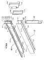
- a conventional tack device includes a stationary part, a slidable part, a fastener-impelling plunger, and a first and second cover plate 22 23.
- the elongated nose plate16 has opposite front and rear faces 163 165, and extends in a vertical direction from the distal end166 in the slidable part 20.
- the second cover plate 22 is mounted to the front face 231 of the first cover plate 23 that is also mounted to the front face of elogated nose plate 16 to define a fastener-impelling track 162 therebetween.
- the first and second cover plates are coupled to the stationary part 14 by welding such that the fastener-impelling track 162 is in alignment with the stationary part 14.
- the fastener-impelling plunger 15 that drivers and discharges a fastener from which proximate to the first cover plate 23 and on the elongated base 12 ,is inserted between the first cover plate 23 and the front face 163 of stationary part 14 therebetween, and goes through from downwardly from distal end that forms a fastener-impelling track 162 to the discharging end 168.
- the fastener-supporting members 18 extending rearwardly from the rear face of elongated nose plate 16 in the transverse direction are disposed on the elongated base 12 and inside of the elongated rails 13 of slidable part 20 and are received in the inner space 144 of stationary part 14 and are in spatial communication with the stationary part 14 when cooperating with the fastener-holding members 146 and peripheral wall 145, to define the fastener-impelling track 162 of elongated nose plate 16 therebetween.
- a plurality of inverted U-shaped staples 8 are perfectly covered on the fastener-supporting members 18 , and slidable in the inverted nail-receiving channel and inverted staple-receiving channel 27 28 that are formed with the spatial communication of the fastener-supporting members 18 of slidable part 20 and fastener-holding members 146 of stationary part 14.
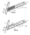
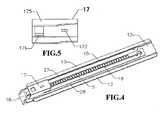
- a plurality of inverted nails are disposed and slidable in the conveted nail-receiving channel 27 of slidable part 20 ,that received in the straight branch portion for nail 143 of stationary part 14 and discharged by the fastener-impelling plunger 15 on the front face 163 of elongated nose plate 16. (SEE FIG.3 ).
- a urging part 17 of slidable part 20 includes bar 171, fastener-pushing member 175 and hook 172.
- the fastener-pushing members 175 of urging part 17 that are pulled by the hook 172 and that push a plurality of U-shaped staples 8 and nails 9 by the bar 171 are properly covering on the fastener-supporting members 18 of slidable part 20.(SEE FIG.5 )
- the conventional tack device is disadvantageous in that the inverted U-shaped staples 7 (SEE FIG.9 ); aren't slidable on the inveted nail-receiving channel 27 and staple-receiving channel 28 when using a multi-purpose fastening tool according to the above descriptions, which is mainly because the side thickness and crown size are a bit different between the U-shaped staple 8 and U-shaped staple that fixed the cable.
- the worker can not operate successfully to load and fasten the U-shaped staples 8 and U-shaped staples 7 and nails 9 at the worksite and which results in undesirably increasing the cost of construction and non-convenient bringing different machines.
- the object of this invention is to provide a tack for a multi-purpose fastening tool which can overcome the aforementional disadvantages of the convenrtional tack device.
- a tack device of present invention includes a stationary part, a fastener-impelling plunger, a slidable part.
- the stationary part has a straight branch portion for nails receiving a plurality of inverted nails and a branch portion for U-shaped staples cooperates with the peripheral wall and fastener-holding members receivng a plurality of inverted U-shaped staples, and has the first and second cover plates respectively includes a converted U-shaped flute, are in alignment with the front face of the stationary part in a vertical direction ;
- the slidable part includes elongated nose plate has opposite front and rear faces, extending in the vertical direction , and elongated base extending rearwardly from the rear face in the transverse direction, and urging part extending rearwardly from elongated nose plate in transverse direction and are perfectly covering on the fastening-supporting members
- the elongated nose plate has U-shaped staple impelling track,U-shaped staple impelling track and nail-impelling track respectively for
- the elongated base extending rearwardly from the elongated nose plate in transverse direction, which has the fastener-supporting members and elongated rails formed with the right and left grooves therebetween, and has elongated projection to cooperate with the the fastener-supporting members that formed with nail passage and U-shaped staple passage thereinto.
- the urging part extending rearwardly from the elongated nose plate in transverse direction, which includes bar, hook and pushable bar together with fastener-pushing members and cooperates with the fastener-supporting members to define the nail passage and U-shaped staple passage;
- the fastener-impelling plunger drives downwardly from the distal end to the discharging end of slidable part in the vertical direction, which is adapted to discharge the U-shaped staple through both left and right section and to discharge the nails through right section and the U-shaped staples through the middle section.
- a nail-discharging opening is disposed adjacent to distal end of elongated nose plate and that extends through the front and rear faces of elongated nose plate in the vertical direction ,which separates the total fastener-impelling_track into U-shaped staple-impelling track, nail-impelling track, and U-shaped staple-impelling track.
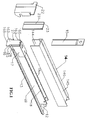
- the present invention includes a slidable part, a stationary part 37, a fastener impelling plunger 36, and the first and second cover plates.
- the slidable part 38 includes elongated nose plate 34 that has opposite front and rear faces 342' 342, extending in the vertical direction , and elongated base 30 extending rearwardly from the rear face 342 in the transverse direction, and urging part 32 extending rearwardly from elongated nose plate 34 in transverse direction and are perfectly covering on the fastening-supporting members 33.
- the elongated nose plate 34 has U-shaped staple impelling track 341,U-shaped staple impelling track 349 and nail-impelling track 348 respectively for a plurality of U-shaped staples 8, U-shaped staples 7 and nails 8 being discharged,which is separated by the a nail-discharging opening 344 that is disposed adjacent to distal end 346 of elongated nose platee 34 and that extends through the front
- the elongated base 30 extending rearwardly from the elongated nose plate 34 in transverse direction, which has the fastener-supporting members 33 and elongated rails 31 formed with right and left grooves 305 306 therebetween, and has elongated projection 35 to cooperate with the the fastener-supporting members 33 that formed with nail passage 335 and U-shaped staple passage 353 thereinto .
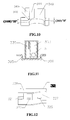
- the urging part 32 extending rearwardly from the elongated nose plate 34 in transverse direction, which includes bar 322, hook 325 and pushable bar 321 together with fastener-pushing members 328 and cooperates with the fastener-supporting members 33 to define the nail passage 335 and U-shaped staple passage 353(SEE FIG12 );
- the stationary part 37 has a straight branch portion for nails 373 receiving a plurality of inverted nails 9 and a branch portion for U-shaped staples 374 that cooperates with the peripheral wall 371 and fastener-holding members 372 receivng a plurality
- the first and second cover plates 38 39 and the fastener-impelling plunger 36 are all set an inverted U-shaped flutes that are in alignment with and the same as the inverted U-shaped flute 343" of discharging end 347 of elongated nose plate 34.
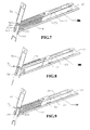
- the U-shaped staples pushed by the fastener-pushing members 328 of urging part 32 ,are slidable in the left and right grooves 306 305 of slidable part 38 and are discharged by the left and right sections 362 364 from the distal end 346 to the discharging end 347 through the U-shaped staple-impelling track 341 of the elongated nose plate 34 in vertical direction (SEE FIG.7 ).
- the nails pushed by the fastener-pushing member 328 of urging part 32 ,are slidable in the right groove 305 of slidable part 38 and discharged by the right section 362 from the distal end 346 to the discharging end 347 through the nail-impelling track 348 of the elongated nose plate 34 in vertical direction (SEE FIG.8 ).
- the U-shaped staples pushed by the fastener-pushing members 328 and pushable bar 321 of urging part 32 ,are slidable in the nail passage 335 and right groove 305 of slidable part 38 and discharged by the middle section 363 from the distal end 346 to the discharging end 347 through the U-shaped staple-impelling track 349 of the elongated nose plate 34 (SEE FIG.9 ) .
Landscapes
- Engineering & Computer Science (AREA)
- Mechanical Engineering (AREA)
- Portable Nailing Machines And Staplers (AREA)
Priority Applications (1)
| Application Number | Priority Date | Filing Date | Title |
|---|---|---|---|
| EP08002107A EP2087966A1 (de) | 2008-02-05 | 2008-02-05 | Heftvorrichtung für ein Mehrzweckbefestigungswerkzeug |
Applications Claiming Priority (1)
| Application Number | Priority Date | Filing Date | Title |
|---|---|---|---|
| EP08002107A EP2087966A1 (de) | 2008-02-05 | 2008-02-05 | Heftvorrichtung für ein Mehrzweckbefestigungswerkzeug |
Publications (1)
| Publication Number | Publication Date |
|---|---|
| EP2087966A1 true EP2087966A1 (de) | 2009-08-12 |
Family
ID=39400920
Family Applications (1)
| Application Number | Title | Priority Date | Filing Date |
|---|---|---|---|
| EP08002107A Withdrawn EP2087966A1 (de) | 2008-02-05 | 2008-02-05 | Heftvorrichtung für ein Mehrzweckbefestigungswerkzeug |
Country Status (1)
| Country | Link |
|---|---|
| EP (1) | EP2087966A1 (de) |
Cited By (4)
| Publication number | Priority date | Publication date | Assignee | Title |
|---|---|---|---|---|
| CN107495821A (zh) * | 2017-09-13 | 2017-12-22 | 麦耀津 | 窗帘挂钩安装装置 |
| CN108081192A (zh) * | 2018-01-24 | 2018-05-29 | 兰州德科工程材料有限公司 | 一种用于u 形钉的插接装置 |
| CN111195881A (zh) * | 2018-11-19 | 2020-05-26 | 丰民金属工业股份有限公司 | 钉枪 |
| CN112091897A (zh) * | 2020-09-04 | 2020-12-18 | 孙玉坤 | 一种适用于小学生的迷你省力订书机 |
Citations (3)
| Publication number | Priority date | Publication date | Assignee | Title |
|---|---|---|---|---|
| US3633811A (en) * | 1969-02-18 | 1972-01-11 | Behrens Friedrich Joh | Apparatus to drive various fastening means |
| US6345754B1 (en) * | 2001-05-04 | 2002-02-12 | Lih-Rong Jeng | Staple magazine for stapler |
| EP1541289A1 (de) * | 2002-07-19 | 2005-06-15 | Max Co., Ltd. | Treiberkonstruktion f r einen stapler |
-
2008
- 2008-02-05 EP EP08002107A patent/EP2087966A1/de not_active Withdrawn
Patent Citations (3)
| Publication number | Priority date | Publication date | Assignee | Title |
|---|---|---|---|---|
| US3633811A (en) * | 1969-02-18 | 1972-01-11 | Behrens Friedrich Joh | Apparatus to drive various fastening means |
| US6345754B1 (en) * | 2001-05-04 | 2002-02-12 | Lih-Rong Jeng | Staple magazine for stapler |
| EP1541289A1 (de) * | 2002-07-19 | 2005-06-15 | Max Co., Ltd. | Treiberkonstruktion f r einen stapler |
Cited By (5)
| Publication number | Priority date | Publication date | Assignee | Title |
|---|---|---|---|---|
| CN107495821A (zh) * | 2017-09-13 | 2017-12-22 | 麦耀津 | 窗帘挂钩安装装置 |
| CN108081192A (zh) * | 2018-01-24 | 2018-05-29 | 兰州德科工程材料有限公司 | 一种用于u 形钉的插接装置 |
| CN108081192B (zh) * | 2018-01-24 | 2024-04-23 | 兰州德科工程材料有限公司 | 一种用于u形钉的插接装置 |
| CN111195881A (zh) * | 2018-11-19 | 2020-05-26 | 丰民金属工业股份有限公司 | 钉枪 |
| CN112091897A (zh) * | 2020-09-04 | 2020-12-18 | 孙玉坤 | 一种适用于小学生的迷你省力订书机 |
Similar Documents
| Publication | Publication Date | Title |
|---|---|---|
| TW200517223A (en) | Integrated check pawl, last nail-retaining, and dry fire lock-out mechanism for fastener-driving tool | |
| EP1371456A3 (de) | Auswechselbares Magazin für ein Werkzeug | |
| EP1147860B1 (de) | Struktur zur Führung von Nägeln zum Frontteil eines Nagelgerätes | |
| EP1364750A3 (de) | Nasen- und Scherenblockanordnung für Nagelgerät und entsprechendes Nagelgerät | |
| EP2087966A1 (de) | Heftvorrichtung für ein Mehrzweckbefestigungswerkzeug | |
| WO2022094190A3 (en) | Powered fastener driver | |
| EP2669054A3 (de) | Nagelkanal für Befestigungswerkzeug | |
| MX343928B (es) | Cartucho dual de grapas para engrapadora quirúrgica. | |
| PT1567307E (pt) | Ponta dividida para accionar parafusos agrupados | |
| WO2002045910A3 (en) | Palm nailer with magazine | |
| US6345754B1 (en) | Staple magazine for stapler | |
| WO2009112474A3 (de) | Heftklammergerät | |
| PL2101954T3 (pl) | Zszywacz | |
| CA2583424A1 (en) | Modular magazine for fastener-driving tool | |
| EP1116556A3 (de) | Führungsaufbau für Nägel im Nasenabschnitt einer Nagelmaschine | |
| DE60325449D1 (de) | Führungsschienensystem im Magazin für ein Nagelgerät | |
| US20060065693A1 (en) | Multi-purpose nail driver | |
| EP1598148A1 (de) | Verbesserter nagelhalter und nagelmaschine mit diesem nagelhalter | |
| AU2002335434A1 (en) | Nail magazine for nailing machine | |
| WO2005102612A3 (en) | Stapler | |
| US20080128468A1 (en) | Magazine assembly for long and short nails | |
| CN212949788U (zh) | 电动订书机 | |
| WO2006009496A8 (en) | Hammer tacker | |
| USD514414S1 (en) | Strip of collated fasteners for fastener-driving tool | |
| JP5135786B2 (ja) | 留付け具 |
Legal Events
| Date | Code | Title | Description |
|---|---|---|---|
| PUAI | Public reference made under article 153(3) epc to a published international application that has entered the european phase |
Free format text: ORIGINAL CODE: 0009012 |
|
| AK | Designated contracting states |
Kind code of ref document: A1 Designated state(s): AT BE BG CH CY CZ DE DK EE ES FI FR GB GR HR HU IE IS IT LI LT LU LV MC MT NL NO PL PT RO SE SI SK TR |
|
| AX | Request for extension of the european patent |
Extension state: AL BA MK RS |
|
| 17P | Request for examination filed |
Effective date: 20090930 |
|
| 17Q | First examination report despatched |
Effective date: 20091028 |
|
| AKX | Designation fees paid |
Designated state(s): AT BE BG CH CY CZ DE DK EE ES FI FR GB GR HR HU IE IS IT LI LT LU LV MC MT NL NO PL PT RO SE SI SK TR |
|
| STAA | Information on the status of an ep patent application or granted ep patent |
Free format text: STATUS: THE APPLICATION IS DEEMED TO BE WITHDRAWN |
|
| 18D | Application deemed to be withdrawn |
Effective date: 20120901 |