EP2087985A2 - Article moulé en résine écorché - Google Patents
Article moulé en résine écorché Download PDFInfo
- Publication number
- EP2087985A2 EP2087985A2 EP09152250A EP09152250A EP2087985A2 EP 2087985 A2 EP2087985 A2 EP 2087985A2 EP 09152250 A EP09152250 A EP 09152250A EP 09152250 A EP09152250 A EP 09152250A EP 2087985 A2 EP2087985 A2 EP 2087985A2
- Authority
- EP
- European Patent Office
- Prior art keywords
- resin
- base material
- molded article
- skinned
- groove
- Prior art date
- Legal status (The legal status is an assumption and is not a legal conclusion. Google has not performed a legal analysis and makes no representation as to the accuracy of the status listed.)
- Withdrawn
Links
- 239000000463 material Substances 0.000 claims abstract description 87
- 238000003780 insertion Methods 0.000 claims abstract description 40
- 230000037431 insertion Effects 0.000 claims abstract description 40
- 239000006261 foam material Substances 0.000 claims abstract description 21
- 230000000295 complement effect Effects 0.000 claims description 6
- 238000000465 moulding Methods 0.000 description 16
- 238000010107 reaction injection moulding Methods 0.000 description 6
- 238000000034 method Methods 0.000 description 5
- 239000011347 resin Substances 0.000 description 4
- 229920005989 resin Polymers 0.000 description 4
- 238000007789 sealing Methods 0.000 description 4
- 230000000694 effects Effects 0.000 description 3
- 238000010276 construction Methods 0.000 description 2
- 238000001746 injection moulding Methods 0.000 description 2
- 230000013011 mating Effects 0.000 description 2
- 239000000843 powder Substances 0.000 description 2
- BZHJMEDXRYGGRV-UHFFFAOYSA-N Vinyl chloride Chemical compound ClC=C BZHJMEDXRYGGRV-UHFFFAOYSA-N 0.000 description 1
- 150000001336 alkenes Chemical class 0.000 description 1
- 230000004075 alteration Effects 0.000 description 1
- 230000001747 exhibiting effect Effects 0.000 description 1
- 238000010438 heat treatment Methods 0.000 description 1
- 238000002347 injection Methods 0.000 description 1
- 239000007924 injection Substances 0.000 description 1
- 238000004519 manufacturing process Methods 0.000 description 1
- JRZJOMJEPLMPRA-UHFFFAOYSA-N olefin Natural products CCCCCCCC=C JRZJOMJEPLMPRA-UHFFFAOYSA-N 0.000 description 1
- 229920003023 plastic Polymers 0.000 description 1
- 239000004033 plastic Substances 0.000 description 1
- 238000002360 preparation method Methods 0.000 description 1
- 230000000630 rising effect Effects 0.000 description 1
- 229920002725 thermoplastic elastomer Polymers 0.000 description 1
Images



Classifications
-
- B—PERFORMING OPERATIONS; TRANSPORTING
- B29—WORKING OF PLASTICS; WORKING OF SUBSTANCES IN A PLASTIC STATE IN GENERAL
- B29C—SHAPING OR JOINING OF PLASTICS; SHAPING OF MATERIAL IN A PLASTIC STATE, NOT OTHERWISE PROVIDED FOR; AFTER-TREATMENT OF THE SHAPED PRODUCTS, e.g. REPAIRING
- B29C44/00—Shaping by internal pressure generated in the material, e.g. swelling or foaming ; Producing porous or cellular expanded plastics articles
- B29C44/02—Shaping by internal pressure generated in the material, e.g. swelling or foaming ; Producing porous or cellular expanded plastics articles for articles of definite length, i.e. discrete articles
- B29C44/12—Incorporating or moulding on preformed parts, e.g. inserts or reinforcements
- B29C44/1257—Joining a preformed part and a lining, e.g. around the edges
-
- B—PERFORMING OPERATIONS; TRANSPORTING
- B29—WORKING OF PLASTICS; WORKING OF SUBSTANCES IN A PLASTIC STATE IN GENERAL
- B29C—SHAPING OR JOINING OF PLASTICS; SHAPING OF MATERIAL IN A PLASTIC STATE, NOT OTHERWISE PROVIDED FOR; AFTER-TREATMENT OF THE SHAPED PRODUCTS, e.g. REPAIRING
- B29C44/00—Shaping by internal pressure generated in the material, e.g. swelling or foaming ; Producing porous or cellular expanded plastics articles
- B29C44/34—Auxiliary operations
- B29C44/35—Component parts; Details or accessories
- B29C44/351—Means for preventing foam to leak out from the foaming device during foaming
-
- B—PERFORMING OPERATIONS; TRANSPORTING
- B29—WORKING OF PLASTICS; WORKING OF SUBSTANCES IN A PLASTIC STATE IN GENERAL
- B29C—SHAPING OR JOINING OF PLASTICS; SHAPING OF MATERIAL IN A PLASTIC STATE, NOT OTHERWISE PROVIDED FOR; AFTER-TREATMENT OF THE SHAPED PRODUCTS, e.g. REPAIRING
- B29C44/00—Shaping by internal pressure generated in the material, e.g. swelling or foaming ; Producing porous or cellular expanded plastics articles
- B29C44/02—Shaping by internal pressure generated in the material, e.g. swelling or foaming ; Producing porous or cellular expanded plastics articles for articles of definite length, i.e. discrete articles
- B29C44/12—Incorporating or moulding on preformed parts, e.g. inserts or reinforcements
- B29C44/14—Incorporating or moulding on preformed parts, e.g. inserts or reinforcements the preformed part being a lining
-
- Y—GENERAL TAGGING OF NEW TECHNOLOGICAL DEVELOPMENTS; GENERAL TAGGING OF CROSS-SECTIONAL TECHNOLOGIES SPANNING OVER SEVERAL SECTIONS OF THE IPC; TECHNICAL SUBJECTS COVERED BY FORMER USPC CROSS-REFERENCE ART COLLECTIONS [XRACs] AND DIGESTS
- Y10—TECHNICAL SUBJECTS COVERED BY FORMER USPC
- Y10T—TECHNICAL SUBJECTS COVERED BY FORMER US CLASSIFICATION
- Y10T428/00—Stock material or miscellaneous articles
- Y10T428/17—Three or more coplanar interfitted sections with securing means
Definitions
- the present invention relates to a skinned, resin-molded article having a resin-molded base material, a skin material in the form of a sheet, and a foam material filled between the base material and the skin material.
- Exterior product such as a skinned, resin-molded article having a base material, a sheet-form skin material covering the base material, and a foam material filled between the base material and the skin material, is put into practical use. Arrangements have been made to the skinned, resin-molded article put into practical use such that the foam material is prevented from leaking and such arrangements were sufficient for practical uses.
- JP 2003-117928 A Conventionally, a skinned, resin-molded article having a skin material with a devised edge for contacting the base material is known from, for example, JP 2003-117928 A .
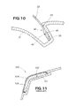
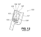
- the technique disclosed in JP 2003-117928 A will be described below with reference to FIGS. 11 and 12 hereof.
- a skinned, resin-molded article 100 is comprised of a resin-molded base material 101, a skin material 103 covering a recessed part 102 of the base material 101, and a foam material 104 filled in the recessed part 102 covered by the skin material 103.
- the skin material 103 includes a design surface 105 covering the recessed part 102 of the base material 101, an insertion portion 107 bent and extending from the design surface 105 toward a base material sidewall 106, and a complexly-bent portion 108 formed on the insertion portion 107.
- the insertion portion 107 having the complexly-bent portion 108 must be fixed against the sidewall of the base material. With such complexly-bent portion, the insertion portion 107 may not be placed in position by simply inserting it along the sidewall 107. The insertion portion 107 is likely be fixed at a position displaced in a direction of arrow (1).
- a skinned, resin-molded article which comprises: a base material having a recessed part defined by sidewalls and a bottom of the base material; a skin material extending over the base material to cover the recessed part and having insertion portions provided at opposite ends of the skin material; and a foam material filled in the recessed part, wherein each of the insertion portions has a planar part held in contact with an adjacent one of the sidewalls, and a groove disposed closer to an end thereof than the planar part, and each of the sidewalls has a projection lockingly tightly engaged in the groove.
- the insertion portion of the skin material By virtue of the thus-simplified construction of the insertion portion of the skin material, it becomes possible to control the thickness of the skin material by reaction injection molding using a male/female mold. As a result, dimensional precision is provided for the skin material.
- the base material is provided with the projection on the sidewall thereof and the insertion portion of the skin material is provided with the groove complementary in shape with the projection, the base material and the skin material can be positioned with increase precision, thereby providing an increased sealing effect between the two materials.
- the projection has a convex hemispherical shape
- the groove has a concave hemispherical shape complementary to the shape of the projection.
- Each of the insertion portions may have a generally flat configuration.
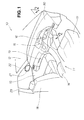
- FIG. 1 showing in perspective a passenger compartment of a vehicle employing a skinned, resin-molded article according to a first embodiment of the present invention.
- the vehicle 10 has a passenger compartment 11, a windshield 12, a glove box 13, a center console 14, a steering wheel 15 shown by a phantom line, a vehicle meter 16, a driver's seat 17, a passenger seat 18, a front left door 19, a door mirror 21, a front pillar 22, and a center pillar 23.
- Designated by reference numeral 30 is a skinned, resin-molded article 30 for use as an instrument panel.
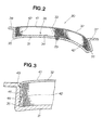
- the skinned, resin-molded article 30 is comprised of a base material 31 molded from a resin material, a skin material 32 placed in fitting engagement with the base material, and a foam material 33 interposed between the base material 31 and the skin material 32.
- the base material 31 includes a bottom 34, sidewalls 35, 35 rising from the bottom 34, a recessed part 36 defined by the bottom 34 and the sidewalls 35, 35, a windshield-side planar part 37 and a steering-wheel-side planar part 38 contiguous with the recessed part 36, and a filling port 39 through which the foam material 33 is filled into the recessed part 36.
- the skin material 32 includes a surface part 41 for covering the recessed part 36 of the base material 31, and insertion portions 42, 42 inserted along the sidewalls 35, 35.
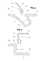
- each insertion portion 42 has a planar part 43 held in contact with the sidewall 35 and a groove 44 formed closer to a distal end than the planar part 43.
- a projection 45 designed to fit into the groove 44. By fitting the projection 45 into the groove 44, the skin material 31 is positioned in place relative to the base material 31.
- the groove 44 has a center-recessed (concave) hemispherical shape.
- the projection 45 also has a hemispherical shape for mated engagement with the groove 44.
- the groove 44 may have a triangular or rectangular shape, or any other shapes, as long as it can achieve the desired mating engagement with the projection 45, though it is desirable for the groove to have a concave hemispherical configuration.
- the projection 45 may have a triangular or rectangular shape, or any other shapes, which are complementary to achieve mated engagement with the groove 44.
- the base material 31 may be produced by injection molding, for example.
- the projection 45 has a center-raised (convex) hemispherical shape which is complementary with the groove 44.
- the convex hemispherical shape is easier to make than an edged shape because a molten resin may flow smoothly. This leads to the advantage that the base material 31 is produced with increased quality.
- the skin material 32 may be produced by, for example, reaction injection molding (RIM molding) using male and female mold halves. By this method, the thickness of the skin material 32 can be controlled. With the reaction injection molding, the concave hemispherical shape is easier to make than an edged shape because a molten resin may flow smoothly. By virtue of the groove 44 having the concave hemispherical shape that is easy to make, it becomes possible to impart improved quality to the skin material 32.
- reaction injection molding reaction injection molding
- reaction injection molding used herein should be construed as a method of molding wherein multiple reactive components, with or without a filling material, are mixed using a pressurized impact within a mixing chamber before the components are injected into a closed mold.
- the base material 31 and the skin material 32 are prepared. Then, the base material 31 is placed in one of the mold halves while the skin material 32 is placed in the other one of the mold halves, e.g., a lower mold half 51 ( FIGS. 6A and 6B ). By bringing an upper mold half 52 ( FIGS. 6A and 6B ) and the lower mold half 51 closer to each other, the insertion portion 42 of the skin material 32 moves in the direction of arrow (2) along the sidewall 35 to be fully inserted, whereupon the planar part 43 is held in contact with the sidewall 35 and the groove 44 is brought into fitting engagement with the projection 45.
- the insertion portion 42 and the projection 45 can be surely placed in position. With the groove 44 and the projection 45 engaged lockingly and tightly with each other, an increased sealing effect is provided between them.
- the projection 45 being of a convex hemispherical shape and the groove 44 being of a concave hemispherical shape, it becomes possible to easily place the skin material 32 in mated engagement with the base material 31.
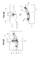
- FIGS. 6A and 6B discussion will be made as to preparations for molding of the skinned, resin-molded article according to the present invention.
- the resin-molded base material 31 As shown in FIG. 6A , the resin-molded base material 31, the skin material 32 molded into a predetermined shape by reaction injection molding, and a molding machine 50 are provided.
- the molding machine 50 is comprised of the upper mold half 52 for placing the base material 31, the lower mold half 52 for mating with the upper mold half 52, a slide 53 that is provided on the upper mold half 52 and slides fit into an undercut part 46 of the base material 31, and a foam material injector 54 disposed closely to the upper mold half 52.
- the upper mold half 52, the lower mold half 51 and the foam material injector 53 jointly form a molding unit 55.
- the lower mold half 51 includes a stepped or shoulder part 56 for allowing the windshield-side planar part 37 to be rested thereon, and a stepped or shoulder part 57 for allowing the steering-wheel-side planar part 38 to be rested thereon.
- the upper mold half 52 includes a gate 59 that guides the foam material 33 injected from the foam material injector 54 into a cavity 58.
- the skin material 32 is inserted or fitted into the base material 31 as shown by arrow (4).
- This fitting-in operation may not necessarily be performed on the molding unit 55 but may be performed during a later step.
- the upper mold half 52 and the lower mold half 51 may be moved toward each other to cause the skin material 32 to be inserted into the base material 31 as shown by arrow (4). This eliminates a manual insertion operation.
- FIGS. 7A and 7B description will be made as to molding clamping with the skinned, resin-molded article placed therein.
- the base material 31 with the skin material 32 inserted is placed on the lower mold half 51 as shown by arrow (5).
- the windshield-side planar part 37 is placed on the windshield-side stepped part 56 while the steering-wheel-side planar part 38 is placed on the steering-wheel-side stepped part 57, so as to position the base material 31 in place.
- the lower mold half 51 is elevated toward the upper mold half 52 as shown by arrow (6).
- the base material 31 is fitted into the cavity 58, and the slide 53 is slid into the undercut part 46. Then, the molding unit 55 is clamped.
- the foam material injector 54 is caused to inject the foam material 33 into the base material 31 via the filling port 39 as shown by arrow (7).
- the foam material 33 is filled into the recessed part 36 covered and closed by the skin material 32.
- the foam material 33 is hardened by appropriately heating the molding unit 55. Then, the molding unit is unclamped, as shown by arrow (8), to thereby allow the skinned, resin-molded article as a finished product to be ejected as shown by arrow (9).
- the skin material 32 may be obtained by, for example, powder slush molding a sheet of soft vinyl chloride or thermoplastic elastomer olefin.
- powder slush molding used herein should be construed as a molding technique wherein powder-form plastics are adhered to a heated slush molding mold surface, fused and then cooled to leave a seal part profile on the surface.
- FIGS. 9A and 9B comparison will be made between the skinned, resin-molded article according to the present invention and a known example resin-molded article.
- the insertion portion 42 is simply inserted along the sidewall 35. Since the sidewall 35 is flat, the insertion portion 42 is not positioned at a desired position as shown by a phantom line, that is, displaced from a target position, as shown by arrow (10).
- the projection 45 is engaged in the groove 44. Because the groove 44 has a hemispherical configuration and the projection 45 has a complementary hemispherical shape, the insertion portion 42 can be easily engaged with the projection 45 and properly positioned in place. With the groove 44 engaged lockingly with the projection 45, an increased sealing effect is provided between them, thus preventing leakage of the foam material.
- the insertion portion 42 lies parallel to the sidewall 35. As a result, a top end 47 of the insertion portion 42 is prevented from warping that allows leakage of the foam material.
- the skin material 32 can be easily inserted into base material 31.
- the insertion portion 42 has a planar part 43 held in contact with the sidewall 35, and a groove 44 provided closer to a top end than the planar part 43.
- the insertion portion 42 has a generally flat surface with a recess of hemispherical shape formed therein. This configuration allows molten resin to flow smoothly during the reaction-injection-molding of the skin material 32, imparting improved quality to the latter.
- the skinned, resin-molded article has been described as being applied to an instrument panel but its usage should not be limited thereto and may be applied to other uses.
Landscapes
- Injection Moulding Of Plastics Or The Like (AREA)
- Moulds For Moulding Plastics Or The Like (AREA)
- Molding Of Porous Articles (AREA)
- Casting Or Compression Moulding Of Plastics Or The Like (AREA)
- Lining Or Joining Of Plastics Or The Like (AREA)
Applications Claiming Priority (1)
| Application Number | Priority Date | Filing Date | Title |
|---|---|---|---|
| JP2008029350A JP2009184316A (ja) | 2008-02-08 | 2008-02-08 | 表皮付き樹脂成形品 |
Publications (2)
| Publication Number | Publication Date |
|---|---|
| EP2087985A2 true EP2087985A2 (fr) | 2009-08-12 |
| EP2087985A3 EP2087985A3 (fr) | 2009-10-21 |
Family
ID=40679489
Family Applications (1)
| Application Number | Title | Priority Date | Filing Date |
|---|---|---|---|
| EP09152250A Withdrawn EP2087985A3 (fr) | 2008-02-08 | 2009-02-06 | Article moulé en résine écorché |
Country Status (4)
| Country | Link |
|---|---|
| US (1) | US20090202775A1 (fr) |
| EP (1) | EP2087985A3 (fr) |
| JP (1) | JP2009184316A (fr) |
| CN (1) | CN101502993A (fr) |
Cited By (2)
| Publication number | Priority date | Publication date | Assignee | Title |
|---|---|---|---|---|
| EP3130440A1 (fr) * | 2015-08-07 | 2017-02-15 | Josef Weischer GmbH & Co. KG | Pièce moulée, dispositif et procédé de production de pièces moulées |
| FR3081749A1 (fr) * | 2018-05-30 | 2019-12-06 | Cera Aps | Procede de realisation d'un ecran de protection acoustique pour vehicule automobile |
Families Citing this family (13)
| Publication number | Priority date | Publication date | Assignee | Title |
|---|---|---|---|---|
| JP5471012B2 (ja) * | 2009-04-27 | 2014-04-16 | 日産自動車株式会社 | 表皮付発泡成形部材、および表皮付発泡成形部材の成形方法 |
| US9061460B2 (en) | 2012-06-20 | 2015-06-23 | Ford Global Technologies, Llc | Skin-covered articles with reaction injection molded foam layer |
| EP2679380A1 (fr) * | 2012-06-28 | 2014-01-01 | RECTICEL Automobilsysteme GmbH | Procédé de fabrication d'une peau flexible présentant au moins un insert collé à celle-ci |
| JP6029937B2 (ja) * | 2012-11-06 | 2016-11-24 | カルソニックカンセイ株式会社 | 発泡成形品およびその製造方法 |
| JP2015098141A (ja) * | 2013-11-20 | 2015-05-28 | 南条装備工業株式会社 | 樹脂製表皮材の製造方法 |
| US20170232416A1 (en) * | 2015-12-30 | 2017-08-17 | Greenmantra Recycling Technologies Ltd. | Reactor For Continuously Treating Polymeric Material |
| US10472487B2 (en) | 2015-12-30 | 2019-11-12 | Greenmantra Recycling Technologies Ltd. | Reactor for continuously treating polymeric material |
| WO2017136957A1 (fr) | 2016-02-13 | 2017-08-17 | Greenmantra Recycling Technologies Ltd. | Asphalte modifié avec un polymère possédant un additif cireux |
| AU2017239181B2 (en) | 2016-03-24 | 2020-12-10 | Greenmantra Recycling Technologies Ltd. | Wax as a melt flow modifier and processing aid for polymers |
| CN114479173A (zh) | 2016-09-29 | 2022-05-13 | 绿色颂歌再生科技有限公司 | 用于处理聚苯乙烯材料的反应器 |
| CN111386305A (zh) | 2017-11-28 | 2020-07-07 | 绿色颂歌再生科技有限公司 | 改性剂在解聚产物中的包封 |
| JP7064133B2 (ja) * | 2018-04-27 | 2022-05-10 | キョーラク株式会社 | 構造体の製造方法及びパネル |
| JP2021525816A (ja) | 2018-05-31 | 2021-09-27 | グリーンマントラ リサイクリング テクノロジーズ リミテッド | 解重合ポリスチレンを介して得られるスチレン系ポリマーの使用 |
Citations (1)
| Publication number | Priority date | Publication date | Assignee | Title |
|---|---|---|---|---|
| JP2003117928A (ja) | 2001-10-10 | 2003-04-23 | Inoac Corp | 表皮一体発泡成形品、その表皮の製造方法及び表皮一体発泡成形品の製造方法 |
Family Cites Families (16)
| Publication number | Priority date | Publication date | Assignee | Title |
|---|---|---|---|---|
| JP3188345B2 (ja) * | 1993-04-24 | 2001-07-16 | 株式会社イノアックコーポレーション | 表皮一体発泡品の製造方法 |
| JP3284001B2 (ja) * | 1994-06-10 | 2002-05-20 | 株式会社イノアックコーポレーション | 表面に表皮付き発泡体を有するプラスチック成形品の製造方法 |
| JP3062011B2 (ja) * | 1994-07-18 | 2000-07-10 | 株式会社イノアックコーポレーション | 発泡成形品の製造方法とそれに用いられる成形型 |
| JP2958247B2 (ja) * | 1994-11-14 | 1999-10-06 | 株式会社イノアックコーポレーション | パッド付きプラスチック成形品の製造方法 |
| JPH08197648A (ja) * | 1995-01-23 | 1996-08-06 | Inoac Corp | パッド付きプラスチック成形品およびその製造方法 |
| JP3303621B2 (ja) * | 1995-09-18 | 2002-07-22 | トヨタ自動車株式会社 | 内装材及びその製造方法 |
| JP3526510B2 (ja) * | 1997-05-15 | 2004-05-17 | 西川化成株式会社 | 発泡成形品及びその製造方法 |
| JPH1158417A (ja) * | 1997-08-20 | 1999-03-02 | Tokai Chem Ind Ltd | パッド付き成形品及びその製造方法 |
| JP3155244B2 (ja) * | 1998-06-23 | 2001-04-09 | 西川化成株式会社 | 表皮一体発泡成形品 |
| US6123356A (en) * | 1998-08-03 | 2000-09-26 | Textron Automotive Company | Construction and method of making air bag closure assembly |
| JP3411969B2 (ja) * | 2000-03-27 | 2003-06-03 | 西川化成株式会社 | 発泡樹脂成形品及びその成形型 |
| JP4454108B2 (ja) * | 2000-06-13 | 2010-04-21 | 株式会社イノアックコーポレーション | 表皮一体発泡成形品用表皮の製造方法 |
| JP3681630B2 (ja) * | 2000-10-30 | 2005-08-10 | 西川化成株式会社 | 表皮一体発泡成形品 |
| KR100536266B1 (ko) * | 2003-02-26 | 2005-12-12 | 덕양산업주식회사 | 인스트루먼트 패널의 부분발포부 결합구조 |
| US6991841B2 (en) * | 2003-05-06 | 2006-01-31 | Lear Corporation | Foam in place composite one-piece hard/soft panel |
| EP1684963B1 (fr) * | 2003-10-16 | 2011-09-21 | Johnson Controls Technology Company | Composant de vehicule et sa methode de fabrication |
-
2008
- 2008-02-08 JP JP2008029350A patent/JP2009184316A/ja active Pending
-
2009
- 2009-02-04 CN CNA2009100048940A patent/CN101502993A/zh active Pending
- 2009-02-06 US US12/366,945 patent/US20090202775A1/en not_active Abandoned
- 2009-02-06 EP EP09152250A patent/EP2087985A3/fr not_active Withdrawn
Patent Citations (1)
| Publication number | Priority date | Publication date | Assignee | Title |
|---|---|---|---|---|
| JP2003117928A (ja) | 2001-10-10 | 2003-04-23 | Inoac Corp | 表皮一体発泡成形品、その表皮の製造方法及び表皮一体発泡成形品の製造方法 |
Cited By (3)
| Publication number | Priority date | Publication date | Assignee | Title |
|---|---|---|---|---|
| EP3130440A1 (fr) * | 2015-08-07 | 2017-02-15 | Josef Weischer GmbH & Co. KG | Pièce moulée, dispositif et procédé de production de pièces moulées |
| DE102015113027B4 (de) * | 2015-08-07 | 2024-03-14 | Josef Weischer GmbH & Co. KG | Formteil |
| FR3081749A1 (fr) * | 2018-05-30 | 2019-12-06 | Cera Aps | Procede de realisation d'un ecran de protection acoustique pour vehicule automobile |
Also Published As
| Publication number | Publication date |
|---|---|
| US20090202775A1 (en) | 2009-08-13 |
| JP2009184316A (ja) | 2009-08-20 |
| EP2087985A3 (fr) | 2009-10-21 |
| CN101502993A (zh) | 2009-08-12 |
Similar Documents
| Publication | Publication Date | Title |
|---|---|---|
| EP2087985A2 (fr) | Article moulé en résine écorché | |
| US9889584B2 (en) | Apparatus and method for manufacturing crash pad | |
| US9757884B2 (en) | Apparatus and method for manufacturing crash pad | |
| US20020125734A1 (en) | Foam-in-place seal and method | |
| EP2868526A1 (fr) | Procédé pour le moulage d'articles en plastique avec un motif de couture | |
| US8932038B2 (en) | Sealing apparatus for foam injection mold | |
| US6126769A (en) | Film laminated plastic moulding as well as process and device for its manufacture | |
| EP2743137A1 (fr) | Elément mobile d'habillage intérieur avec une fonction d'arrêt | |
| ES2873025T3 (es) | Procedimiento para producir una pieza moldeada con una superficie visible con diferentes zonas de superficie | |
| EP1153725A1 (fr) | Procédé et dispositif pour mouler à chaud des articles en matière thermoplastique | |
| US6413460B1 (en) | Method of forming a partially covered panel | |
| US7943074B2 (en) | Method and tool for producing a plastic component with a decorative layer, a backing layer and an additional molded part attached thereto | |
| KR101843886B1 (ko) | 자동차 내장재 성형장치 및 방법 | |
| JP5617745B2 (ja) | 車両用内装材の製造方法 | |
| CN107073772B (zh) | 立柱装饰物的制造方法 | |
| US20070264474A1 (en) | Component for a vehicle interior and a mold assembly and a method for assembling the component | |
| US9233651B2 (en) | Interior automotive panels and method of making thereof | |
| JP3548243B2 (ja) | 複合型熱可塑性樹脂成形品及び複合型熱可塑性樹脂成形品の製造方法 | |
| JP3135847B2 (ja) | 発泡成形品の製造方法 | |
| JP2005329544A (ja) | 2色成形品及びその成形方法 | |
| JP3784321B2 (ja) | 車両用ライニング部材の成形装置及び成形方法 | |
| US20240227651A1 (en) | Plastic article with faux stitching and method of forming same | |
| US20080299246A1 (en) | Multiple-shot injection mold assembly and a component having a retention rib made therewith | |
| JP2008030260A (ja) | 合成樹脂積層品の製造方法及び製造装置並びに合成樹脂積層品 | |
| JPH06226757A (ja) | 発泡成形品のコア材およびそれを用いた発泡成形品の製造方法 |
Legal Events
| Date | Code | Title | Description |
|---|---|---|---|
| PUAI | Public reference made under article 153(3) epc to a published international application that has entered the european phase |
Free format text: ORIGINAL CODE: 0009012 |
|
| 17P | Request for examination filed |
Effective date: 20090206 |
|
| AK | Designated contracting states |
Kind code of ref document: A2 Designated state(s): AT BE BG CH CY CZ DE DK EE ES FI FR GB GR HR HU IE IS IT LI LT LU LV MC MK MT NL NO PL PT RO SE SI SK TR |
|
| AX | Request for extension of the european patent |
Extension state: AL BA RS |
|
| PUAL | Search report despatched |
Free format text: ORIGINAL CODE: 0009013 |
|
| AK | Designated contracting states |
Kind code of ref document: A3 Designated state(s): AT BE BG CH CY CZ DE DK EE ES FI FR GB GR HR HU IE IS IT LI LT LU LV MC MK MT NL NO PL PT RO SE SI SK TR |
|
| AX | Request for extension of the european patent |
Extension state: AL BA RS |
|
| 17Q | First examination report despatched |
Effective date: 20091215 |
|
| AKX | Designation fees paid |
Designated state(s): DE FR GB |
|
| STAA | Information on the status of an ep patent application or granted ep patent |
Free format text: STATUS: THE APPLICATION IS DEEMED TO BE WITHDRAWN |
|
| 18D | Application deemed to be withdrawn |
Effective date: 20151028 |