EP2088021A2 - Recouvrement de pièces de guidage d'une porte coulissante de véhicule automobile - Google Patents
Recouvrement de pièces de guidage d'une porte coulissante de véhicule automobile Download PDFInfo
- Publication number
- EP2088021A2 EP2088021A2 EP09000987A EP09000987A EP2088021A2 EP 2088021 A2 EP2088021 A2 EP 2088021A2 EP 09000987 A EP09000987 A EP 09000987A EP 09000987 A EP09000987 A EP 09000987A EP 2088021 A2 EP2088021 A2 EP 2088021A2
- Authority
- EP
- European Patent Office
- Prior art keywords
- sliding door
- guide rail
- cover
- door according
- web
- Prior art date
- Legal status (The legal status is an assumption and is not a legal conclusion. Google has not performed a legal analysis and makes no representation as to the accuracy of the status listed.)
- Granted
Links
- 238000004804 winding Methods 0.000 claims description 31
- 239000002985 plastic film Substances 0.000 claims description 3
- 229920006255 plastic film Polymers 0.000 claims description 3
- 238000004026 adhesive bonding Methods 0.000 claims description 2
- 238000002347 injection Methods 0.000 claims description 2
- 239000007924 injection Substances 0.000 claims description 2
- 238000004073 vulcanization Methods 0.000 claims 1
- 230000008878 coupling Effects 0.000 description 4
- 238000010168 coupling process Methods 0.000 description 4
- 238000005859 coupling reaction Methods 0.000 description 4
- 230000000694 effects Effects 0.000 description 3
- 230000006378 damage Effects 0.000 description 2
- 230000003796 beauty Effects 0.000 description 1
- 238000006073 displacement reaction Methods 0.000 description 1
- 239000000428 dust Substances 0.000 description 1
- 238000005538 encapsulation Methods 0.000 description 1
- 230000010354 integration Effects 0.000 description 1
- 238000012423 maintenance Methods 0.000 description 1
- 238000004519 manufacturing process Methods 0.000 description 1
- 239000000463 material Substances 0.000 description 1
- 230000000149 penetrating effect Effects 0.000 description 1
- 230000002093 peripheral effect Effects 0.000 description 1
- 230000002787 reinforcement Effects 0.000 description 1
Images


Classifications
-
- B—PERFORMING OPERATIONS; TRANSPORTING
- B60—VEHICLES IN GENERAL
- B60J—WINDOWS, WINDSCREENS, NON-FIXED ROOFS, DOORS, OR SIMILAR DEVICES FOR VEHICLES; REMOVABLE EXTERNAL PROTECTIVE COVERINGS SPECIALLY ADAPTED FOR VEHICLES
- B60J5/00—Doors
- B60J5/04—Doors arranged at the vehicle sides
- B60J5/0412—Lower door structure
-
- B—PERFORMING OPERATIONS; TRANSPORTING
- B60—VEHICLES IN GENERAL
- B60J—WINDOWS, WINDSCREENS, NON-FIXED ROOFS, DOORS, OR SIMILAR DEVICES FOR VEHICLES; REMOVABLE EXTERNAL PROTECTIVE COVERINGS SPECIALLY ADAPTED FOR VEHICLES
- B60J5/00—Doors
- B60J5/04—Doors arranged at the vehicle sides
- B60J5/06—Doors arranged at the vehicle sides slidable; foldable
-
- B—PERFORMING OPERATIONS; TRANSPORTING
- B60—VEHICLES IN GENERAL
- B60R—VEHICLES, VEHICLE FITTINGS, OR VEHICLE PARTS, NOT OTHERWISE PROVIDED FOR
- B60R13/00—Elements for body-finishing, identifying, or decorating; Arrangements or adaptations for advertising purposes
- B60R13/02—Internal Trim mouldings ; Internal Ledges; Wall liners for passenger compartments; Roof liners
- B60R13/0237—Side or rear panels
- B60R13/0243—Doors
-
- B—PERFORMING OPERATIONS; TRANSPORTING
- B60—VEHICLES IN GENERAL
- B60R—VEHICLES, VEHICLE FITTINGS, OR VEHICLE PARTS, NOT OTHERWISE PROVIDED FOR
- B60R13/00—Elements for body-finishing, identifying, or decorating; Arrangements or adaptations for advertising purposes
- B60R13/02—Internal Trim mouldings ; Internal Ledges; Wall liners for passenger compartments; Roof liners
- B60R2013/0287—Internal Trim mouldings ; Internal Ledges; Wall liners for passenger compartments; Roof liners integrating other functions or accessories
-
- E—FIXED CONSTRUCTIONS
- E05—LOCKS; KEYS; WINDOW OR DOOR FITTINGS; SAFES
- E05D—HINGES OR SUSPENSION DEVICES FOR DOORS, WINDOWS OR WINGS
- E05D15/00—Suspension arrangements for wings
- E05D15/06—Suspension arrangements for wings for wings sliding horizontally more or less in their own plane
- E05D15/10—Suspension arrangements for wings for wings sliding horizontally more or less in their own plane movable out of one plane into a second parallel plane
- E05D15/1065—Suspension arrangements for wings for wings sliding horizontally more or less in their own plane movable out of one plane into a second parallel plane with transversely moving track
- E05D2015/1084—Suspension arrangements for wings for wings sliding horizontally more or less in their own plane movable out of one plane into a second parallel plane with transversely moving track the carriage being directly linked to the fixed frame, e.g. slidingly
- E05D2015/1086—Suspension arrangements for wings for wings sliding horizontally more or less in their own plane movable out of one plane into a second parallel plane with transversely moving track the carriage being directly linked to the fixed frame, e.g. slidingly swingingly, e.g. on arms
- E05D2015/1089—Suspension arrangements for wings for wings sliding horizontally more or less in their own plane movable out of one plane into a second parallel plane with transversely moving track the carriage being directly linked to the fixed frame, e.g. slidingly swingingly, e.g. on arms the carriage having means for preventing rotation of the wing
-
- E—FIXED CONSTRUCTIONS
- E05—LOCKS; KEYS; WINDOW OR DOOR FITTINGS; SAFES
- E05Y—INDEXING SCHEME ASSOCIATED WITH SUBCLASSES E05D AND E05F, RELATING TO CONSTRUCTION ELEMENTS, ELECTRIC CONTROL, POWER SUPPLY, POWER SIGNAL OR TRANSMISSION, USER INTERFACES, MOUNTING OR COUPLING, DETAILS, ACCESSORIES, AUXILIARY OPERATIONS NOT OTHERWISE PROVIDED FOR, APPLICATION THEREOF
- E05Y2201/00—Constructional elements; Accessories therefor
- E05Y2201/10—Covers; Housings
- E05Y2201/11—Covers
-
- E—FIXED CONSTRUCTIONS
- E05—LOCKS; KEYS; WINDOW OR DOOR FITTINGS; SAFES
- E05Y—INDEXING SCHEME ASSOCIATED WITH SUBCLASSES E05D AND E05F, RELATING TO CONSTRUCTION ELEMENTS, ELECTRIC CONTROL, POWER SUPPLY, POWER SIGNAL OR TRANSMISSION, USER INTERFACES, MOUNTING OR COUPLING, DETAILS, ACCESSORIES, AUXILIARY OPERATIONS NOT OTHERWISE PROVIDED FOR, APPLICATION THEREOF
- E05Y2201/00—Constructional elements; Accessories therefor
- E05Y2201/60—Suspension or transmission members; Accessories therefor
- E05Y2201/622—Suspension or transmission members elements
- E05Y2201/684—Rails; Tracks
-
- E—FIXED CONSTRUCTIONS
- E05—LOCKS; KEYS; WINDOW OR DOOR FITTINGS; SAFES
- E05Y—INDEXING SCHEME ASSOCIATED WITH SUBCLASSES E05D AND E05F, RELATING TO CONSTRUCTION ELEMENTS, ELECTRIC CONTROL, POWER SUPPLY, POWER SIGNAL OR TRANSMISSION, USER INTERFACES, MOUNTING OR COUPLING, DETAILS, ACCESSORIES, AUXILIARY OPERATIONS NOT OTHERWISE PROVIDED FOR, APPLICATION THEREOF
- E05Y2600/00—Mounting or coupling arrangements for elements provided for in this subclass
- E05Y2600/10—Adjustable
- E05Y2600/30—Adjustment motion
- E05Y2600/31—Linear motion
-
- E—FIXED CONSTRUCTIONS
- E05—LOCKS; KEYS; WINDOW OR DOOR FITTINGS; SAFES
- E05Y—INDEXING SCHEME ASSOCIATED WITH SUBCLASSES E05D AND E05F, RELATING TO CONSTRUCTION ELEMENTS, ELECTRIC CONTROL, POWER SUPPLY, POWER SIGNAL OR TRANSMISSION, USER INTERFACES, MOUNTING OR COUPLING, DETAILS, ACCESSORIES, AUXILIARY OPERATIONS NOT OTHERWISE PROVIDED FOR, APPLICATION THEREOF
- E05Y2800/00—Details, accessories and auxiliary operations not otherwise provided for
- E05Y2800/34—Form stability
- E05Y2800/342—Deformable
-
- E—FIXED CONSTRUCTIONS
- E05—LOCKS; KEYS; WINDOW OR DOOR FITTINGS; SAFES
- E05Y—INDEXING SCHEME ASSOCIATED WITH SUBCLASSES E05D AND E05F, RELATING TO CONSTRUCTION ELEMENTS, ELECTRIC CONTROL, POWER SUPPLY, POWER SIGNAL OR TRANSMISSION, USER INTERFACES, MOUNTING OR COUPLING, DETAILS, ACCESSORIES, AUXILIARY OPERATIONS NOT OTHERWISE PROVIDED FOR, APPLICATION THEREOF
- E05Y2900/00—Application of doors, windows, wings or fittings thereof
- E05Y2900/50—Application of doors, windows, wings or fittings thereof for vehicles
- E05Y2900/53—Type of wing
- E05Y2900/531—Doors
Definitions
- the present invention relates to a covering device for guide parts of a door leaf of a motor vehicle sliding door and a sliding door on the sliding door leaf inside a guide rail is provided.
- Sliding doors find a variety of applications in motor vehicles, especially in public transport vehicles, but increasingly in large-capacity sedans, which are designed to transport five or more people.
- a swing-sliding door for vehicles known, on the inside of a door leaf, essentially in the region of the horizontal center, a horizontally extending track rail is arranged. In this engages a role leadership.
- This sliding door is designed as an external sliding door. An opening movement takes place in that first of all a door leaf is displaced outwards and at the same time obliquely upwards and then moved along the outer wall of the vehicle. The lifting of the door is done, for example, at an angle of 45 ° obliquely upward.
- the drive for opening and closing the door leaf is electromechanical.
- the guide systems known in the art are hardly usable due to the arrangement of a guide mechanism at the upper end portion of the door leaf for convertible or coupe models. Because in such vehicles, a frame-side upper guide a lowerable window is not provided. In the absence of an upper door frame, the use of conventional sliding door guidance systems for such motor vehicles has hitherto been out of the question.
- the present invention is therefore based on the object to provide a guide mechanism for a sliding door of a motor vehicle, which is also universally suitable for door leaves and sliding doors with frameless content Erten retractable windows.
- the guide mechanism should also be particularly easy to install and maintain. Also, the guide mechanism for the vehicle occupants should be substantially hidden or concealed.
- the sliding door has a door leaf and a guide rail associated with the door leaf.
- This guide rail is engaged with a slider.
- the sliding element is connected via a pivotally mounted pivot lever with the support structure or with the body of the vehicle.
- the sliding element is located at a free end portion of the articulated by means of its other end portion on the body or on the support structure pivot lever.
- a covering device is provided for the inside of the sliding door leaf provided or arranged thereon guide rail. This is designed to separate or cover the guide rail of the guide mechanism relative to the vehicle interior. In this way, the guide rail or the entire guide mechanism for the vehicle occupants can be covered or concealed in barely visible manner.
- such a covering device has the advantage that the vehicle occupants can not inadvertently get into the guide mechanism with fingers or with items of clothing or the like objects. Otherwise, injuries or damage to objects or body parts entering the guidance system would be feared.
- the cover prevents the ingress of dust and dirt into the guide mechanism. It thus contributes to a smooth, low-maintenance and reliable operation of the entire guide mechanism.
- the covering device has a longitudinal extent corresponding to the length of the guide rail.
- the covering device extends over the entire guide rail or at least over the part of the guide rail, which is actively used by the sliding element when opening and closing the door leaf as a travel distance.
- the covering device has individual elastically yielding elements, such as brushes, which close the open to the door interior region of the guide mechanism. Through these brushes or a comparable comb-like arrangement of elastically yielding fingers of the pivot lever is guided. In this way it can be achieved that only the components required for guidance, namely pivoting lever and / or sliding element reach the covering device piercing or penetrating with the associated guide rail in engagement.
- individual elastically yielding elements such as brushes
- a cover sheet is provided for the covering device. This extends substantially over the entire longitudinal extent of the guide rail.
- the longitudinal extent of the cover web corresponds at least to the length of the travel of the sliding element on the guide rail between the two End positions, namely opening and closing position of the door leaf.
- the cover web is coupled to the sliding element or with the pivot lever.
- the coupling is such that the cover web when moving the door leaf between the open or closed position relative to the guide rail performs a relative movement, preferably in the direction of the longitudinal extension of the guide rail.
- the cover web can be freely movable relative to the sliding element and / or the pivoting lever, at least within certain limits.
- the cover web can be wound up on its winding longitudinally lying in the vehicle longitudinal direction end portions, or in the region of the free ends of the guide rail coming end portions each on a winding shaft.
- the spaced-apart winding shafts are oppositely spring-loaded, so that the cover web is always kept under tension via the provided on the winding shaft spring.
- the winding shafts for the cover web are locally fixed with respect to the guide rail of the guide mechanism. They preferably come to lie in the amount of the region of the opposite end portions of the guide rail.
- cover web is guided between the parallel to the longitudinal extent of the guide rail spaced from each other winding shafts in opposite guides.
- cover sheet guides extend between brackets or bearings for the winding shafts of the cover sheet.
- the Abdeckbahn preferably extend parallel to the longitudinal extent of the guide rail and engage around the cover laterally. For this purpose, they preferably have a U-shaped cross-sectional profile which encloses a respective side edge of the cover web.
- the Abdeckbahn operationen open directly into the brackets or in the camp for the winding shafts. It can be provided in particular that the Abdeckbahn facilityen are integrally connected to the end-side brackets or bearings for the winding shafts. While the Abdeckbahn entryen have a substantially U-shaped and perpendicular to the winding web plane relatively narrow cross-sectional profile, the brackets are formed widened towards the longitudinal end. At or between these flange-widened portions of the winding shaft reaches the front end to the plant. The widened portions of the brackets in the area of the winding shaft bearing thus provide a guide for the cover when winding or unwinding available.
- the cover web an intermediate piece has, which is penetrated by the pivot arm or the slider of the guide mechanism.
- This intermediate piece preferably has an increased stability and strength compared with the rest of the cover sheet. It serves for the movement coupling of slider or swivel arm with the cover. If, when the door leaf is being opened or closed, the slider is displaced in the guide rail, this relative movement is transmitted directly to the cover track via the intermediate piece.
- the intermediate piece provides a driver function and a movement coupling of slider or swivel arm with the cover.
- the intermediate piece is preferably integrated flush into the cover track and has a passage opening adapted to the geometry of the pivoting arm or of the slider. This is designed such that the intermediate piece receives the pivot arm or the slider clearance.
- the intermediate piece is connected to the cover web by gluing, vulcanizing and / or by means of encapsulation or injection into the cover web with this. It can further be provided that the cover web is connected adjacent to the intermediate piece over its entire width with the intermediate piece. However, it can also be provided that the cover web is formed continuously and the intermediate piece only provides a structural reinforcement in sections, thus only partially, preferably in the middle between the side edges of the cover a structurally stale passage opening for the swivel arm or the slider is available ,
- the longitudinal extension of the intermediate piece is relatively short parallel to the longitudinal extension of the cover web guides or the guide rail, since the intermediate piece is only partially suitable for winding on the winding shaft due to its structurally stiffening configuration.
- the intermediate piece is thus positioned in every possible position of the sliding door leaf between the end-side winding shafts.
- the distance between the two winding shafts or winding shaft mounts can be kept as small as possible, it is advantageous if the longitudinal extension of the intermediate piece on each side of the pivot arm passing through it corresponds approximately to the width of the cover.
- the cover sheet has a plastic film which is particularly easy to install and inexpensive to manufacture.
- a plastic film can be provided with a surface texture which is adapted to the contour or the nature of the surrounding door inner lining.
- At least one guide provided for the covering web is arranged directly on the guide rail for the sliding element.
- the cover web guides and the guide rail extend substantially parallel to one another and at least one cover web guide arranged directly on the guide rail can in particular be integrally connected to the guide rail or the cover web guide can be integrated directly in the guide rail for the slide element.
- the guide rail for the sliding element which essentially has a U-shaped profile, has a further guide groove for the cover web on the front side of a somewhat widened profile leg.
- the entire covering device namely the covering web, the cover web guides and the associated winding shafts and holder below an armrest of the door inner lining.
- the guide rail for the guide mechanism is also arranged below the armrest of the door inner lining or is covered by this. In this way, even by the arrangement of the guide rail and the associated cover device below an armrest for the vehicle occupant possible verborgende arrangement of the guide or covering mechanism can be provided.
- the invention relates to a cover device for the guide mechanism of a previously described sliding door.
- the covering device has at least one covering web, which is rolled up on winding shafts arranged at a distance from one another.
- the cover sheet is kept tensioned.
- it is traversed by an arm engaging with the guide rail of the guide mechanism, so that it is moved along in an opening or closing movement of the door a guide of the pivot arm in the guide rail and the other sections of the guide mechanism against the motor vehicle interior separated, separated and closes ,
- FIG. 1 is shown in a perspective view of the door 10 of a sliding door of a motor vehicle.
- the Door leaf 10 has two door leaf side guide rails 12, 62, while the body side another guide rail 52 is provided.
- sliding elements 18, 56 out which are articulated via pivot arms 14, 54, 64 alternately either on the vehicle body or on the door leaf.
- the lower, provided in the sill area guide rails 62, 52 and associated sliding elements 56 form a parallelogram-like arrangement.
- the guide rail 62 is arranged on the inside of the door leaf 10.
- the associated sliding member 56 is articulated via a pivot arm 54 body or support structure side. The reverse is true with the other arranged in the sill area guide rail 52.
- slider is slidably disposed, which is coupled via a pivot arm 64 with the door 10.
- a further guide rail 32 is provided in the belt line area of the door leaf on the inside of the door leaf, in which a, as in FIG. 4 shown, a slider 18 is slidably guided.
- Sliding element 18, which is not explicitly shown, is connected via a pivot lever 14 to the motor vehicle body or to the supporting structure of the motor vehicle.
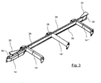
- the cover 12 extends substantially over the entire length of the upper guide rail 32, as in particular FIG. 2 evident. It has two substantially parallel to each other and parallel to the guide rail 32 extending upper and lower guide profiles 28, 30, in which a cover web 24 or a blind is slidably guided.
- the covering web 24 is rolled up on the longitudinal ends of the covering device 12 on a respective spring-loaded winding shaft 34, 36. The effect of the spring-loaded winding shafts that the flexible and deformable cover panel 24 is always maintained at tension and that the cover web can be moved together with the pivot lever 14 or with the slider 18 mounted in the guide rail 32 relative to the guide rail 32.
- an intermediate piece 26 is provided in particular on the cover web 24, which has a relative to the cover sheet 24 reinforced or stiffened structure material.
- This intermediate piece 26 also has a passage opening for the pivoting lever 14, which in this way the cover sheet 24 is interspersed with the lying on the other side of the cover sheet 24 sliding member 18 via a bearing pin 16.
- FIG. 3 shows a total of four different positions of the pivot lever 14, 14 ', 14''and14'', which successively indicate the individual positions of the pivot lever 14 when opening the sliding door.
- the winding shafts 34, 36 are mounted in brackets 20, 22. This, widened to the free end portion of the cover towards trained holders provide a lateral guide for the wound cover sheet 24.
- FIG. 5 Furthermore, the integration of the guide rail 32 in the armrest 11 of a door inner lining is indicated.
- the associated cover device 12 with its cover shade 24 connects directly to the lower end portion of the armrest 11, so that this area for the vehicle occupants remains substantially unnoticed and poorly visible.
- cover panel 24 is at its upper and peripheral portions in each case by an associated Abdeckbahn Entry 28, 30 includes.
- Overlying cover track guide 28 is directly connected to the guide rail 32. Alternatively, it can also be integrated directly into the guide rail 32.
- the guide rail 32 is formed as an upwardly open guide rail, which then comes into contact with the lower covering sheet guide 30 accordingly. It is also within the scope of the invention that the guide rail 32 is arranged open like the guide rail 62 to the side, and that the cover 12, but in particular the cover sheet 24 corresponding to 90 ° is rotated, so that the pivot arm 14, the cover 12 is not horizontal, but passes through vertically.
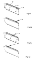
- FIGS. 6a to 6d also show successively the individual positions of the intermediate piece 26 and the pivot lever 14 in an opening operation of the door leaf.
- FIG. 6a the door is in its closed position.
- the pivoting lever 14 extends substantially parallel to the covering device 12.
- the entire door leaf is moved over the pivoting levers 14, 54, 64 into the inward opening FIG. 6b shown position transferred.
- the door is pushed further to the right, so that the pivot lever 14 and the hinged thereto slider 18 in the guide rail 32 moves further to the left until the door their Endanschlags- or opening position in FIG. 6d has reached.
- FIGS. 6a to 6d the sliding relative to the vehicle body door is selected as a reference system.
- the pivot lever 14 moves relative to the supposedly fixed door leaf. In practice, however, this is the reverse.
- the pivot lever 14 is with his, facing away from the door pivotally fixed to the body of the vehicle, so that the door 10, starting from the representation according to FIG. 6a up to the presentation after FIG. 6d successively transferred to the right in its open position.
Landscapes
- Engineering & Computer Science (AREA)
- Mechanical Engineering (AREA)
- Power-Operated Mechanisms For Wings (AREA)
- Window Of Vehicle (AREA)
- Wing Frames And Configurations (AREA)
- Closing And Opening Devices For Wings, And Checks For Wings (AREA)
Applications Claiming Priority (1)
| Application Number | Priority Date | Filing Date | Title |
|---|---|---|---|
| DE102008008128A DE102008008128A1 (de) | 2008-02-08 | 2008-02-08 | Abdeckung von Führungsteilen einer Kraftfahrzeugschiebetür |
Publications (3)
| Publication Number | Publication Date |
|---|---|
| EP2088021A2 true EP2088021A2 (fr) | 2009-08-12 |
| EP2088021A3 EP2088021A3 (fr) | 2009-11-04 |
| EP2088021B1 EP2088021B1 (fr) | 2014-07-02 |
Family
ID=40626729
Family Applications (1)
| Application Number | Title | Priority Date | Filing Date |
|---|---|---|---|
| EP09000987.9A Not-in-force EP2088021B1 (fr) | 2008-02-08 | 2009-01-24 | Recouvrement de pièces de guidage d'une porte coulissante de véhicule automobile |
Country Status (4)
| Country | Link |
|---|---|
| US (1) | US20090199480A1 (fr) |
| EP (1) | EP2088021B1 (fr) |
| CN (1) | CN101550792B (fr) |
| DE (1) | DE102008008128A1 (fr) |
Cited By (5)
| Publication number | Priority date | Publication date | Assignee | Title |
|---|---|---|---|---|
| WO2011045052A1 (fr) * | 2009-10-14 | 2011-04-21 | Dura Automotive Body & Glass Systems Gmbh | Agencement d'habillage pour un bras pivotant d'une porte de camion |
| DE102013209351A1 (de) | 2012-05-22 | 2013-11-28 | Ford Global Technologies, Llc | Schiebetür eines Kraftfahrzeugs |
| CN104044437A (zh) * | 2013-03-15 | 2014-09-17 | 现代自动车株式会社 | 隐形滑动车门饰件结构 |
| US11305707B2 (en) * | 2020-06-08 | 2022-04-19 | Hyundai Motor Company | Structure for shielding side sill for sliding door vehicle |
| DE102023113634A1 (de) * | 2023-05-24 | 2024-11-28 | Brose Fahrzeugteile Se & Co. Kommanditgesellschaft, Bamberg | Fahrzeugtürbaugruppe mit einer Antriebsvorrichtung |
Families Citing this family (16)
| Publication number | Priority date | Publication date | Assignee | Title |
|---|---|---|---|---|
| DE202010010233U1 (de) * | 2010-07-14 | 2011-11-14 | MACO Vermögensverwaltung GmbH | Beschlagvorrichtung |
| US8794688B2 (en) * | 2012-01-24 | 2014-08-05 | Chrysler Group Llc | Door assembly for a vehicle |
| US20150089875A1 (en) * | 2013-09-27 | 2015-04-02 | Roger Malmrose | Hardware for opening a frameless window into laterally displaced parallel positions |
| KR101673338B1 (ko) * | 2014-11-06 | 2016-11-07 | 현대자동차 주식회사 | 차량용 슬라이딩 도어 록킹장치 |
| US10179551B2 (en) * | 2016-04-20 | 2019-01-15 | Ford Global Technologies Llc | Sliding joint applique |
| US10053027B2 (en) | 2016-04-20 | 2018-08-21 | Ford Global Technologies Llc | Sliding joint applique |
| US10480233B2 (en) * | 2016-12-16 | 2019-11-19 | Ford Global Technologies, Llc | Hidden sliding door assembly for a motor vehicle |
| DE102017202114B4 (de) * | 2017-02-10 | 2023-08-31 | Bayerische Motoren Werke Aktiengesellschaft | Kraftfahrzeug |
| CN109610968B (zh) * | 2018-12-07 | 2020-09-22 | 广东东箭汽车科技股份有限公司 | 汽车滑移门系统和汽车 |
| KR20200071952A (ko) * | 2018-12-12 | 2020-06-22 | 현대자동차주식회사 | 대향형 슬라이딩 도어의 슬라이딩 트림 커버 구조 |
| WO2021252657A1 (fr) * | 2020-06-11 | 2021-12-16 | Shanghai Yanfeng Jinqiao Automotive Trim Systems Co. Ltd. | Pièce d'intérieur de véhicule |
| US12139946B1 (en) | 2021-09-10 | 2024-11-12 | Apple Inc. | Sliding door |
| WO2023048664A1 (fr) * | 2021-09-27 | 2023-03-30 | Standard Profi̇l Otomoti̇v Sanayi̇ Ve Ti̇caret Anoni̇m Şi̇rketi̇ | Guide monolithique pour fenêtres coulissantes dans des véhicules |
| CN114801668A (zh) * | 2022-05-06 | 2022-07-29 | 岚图汽车科技有限公司 | 一种无框滑移门的开闭结构及汽车 |
| CN115817132B (zh) * | 2022-09-26 | 2024-11-29 | 重庆长安汽车股份有限公司 | 一种滑轨隐藏式滑门铰链安装结构、滑门及车辆 |
| CN116788360B (zh) * | 2023-06-27 | 2025-10-28 | 上汽通用汽车有限公司 | 滑移门门槛装置和包含其的汽车 |
Citations (4)
| Publication number | Priority date | Publication date | Assignee | Title |
|---|---|---|---|---|
| US3605338A (en) | 1968-09-30 | 1971-09-20 | Lunke & Sohn Gmbh | Sliding door,particularly for motor vehicles |
| DE4315616A1 (de) | 1992-09-16 | 1994-11-17 | Bode & Co Geb | Ausschwenkbare Schiebetür für Fahrzeuge, insbesondere Fahrzeuge, des öffentlichen Personenverkehrs |
| FR2888870A1 (fr) | 2005-07-19 | 2007-01-26 | Peugeot Citroen Automobiles Sa | Dispositif d'obturation d'une ouverture d'acces d'un rail de coulissement |
| WO2008095728A1 (fr) | 2007-02-08 | 2008-08-14 | Dura Automotive Body & Glass Systems Gmbh | Porte coulissante pour un véhicule à moteur |
Family Cites Families (20)
| Publication number | Priority date | Publication date | Assignee | Title |
|---|---|---|---|---|
| US3090048A (en) * | 1959-07-02 | 1963-05-21 | Cee Bee Mfg Co Inc | Fabric face plastic belting |
| DE1506100A1 (de) * | 1967-02-22 | 1969-06-04 | Sigmatex Ag | Selbsttaetiger Gurtaufroller fuer Sicherheitsgurte |
| DE2443472A1 (de) * | 1974-09-11 | 1976-03-25 | Lunke & Sohn Gmbh | Schiebetuer fuer fahrzeuge, insbesondere kraftfahrzeuge |
| GB2080743B (en) * | 1980-07-17 | 1984-07-25 | Nissan Motor | Guide rail for a vehicle sliding door |
| US5203116A (en) * | 1992-05-07 | 1993-04-20 | Hong Jen Chen | Rail assembly for sliding door |
| DE4314115A1 (de) * | 1993-04-29 | 1994-11-03 | Opel Adam Ag | Schiebetür, insbesondere für Kraftfahrzeuge |
| JPH0776224A (ja) * | 1993-09-06 | 1995-03-20 | Aisin Seiki Co Ltd | オートスライドドア |
| US5588609A (en) * | 1994-04-13 | 1996-12-31 | Nsk Ltd. | Seat belt winding device |
| DE19634369C1 (de) * | 1996-08-26 | 1997-09-18 | Daimler Benz Ag | Vorrichtung zum Führen einer ausschwenkbaren Schiebetür an einer Fahrzeugkarosserie |
| US6358073B1 (en) * | 2000-09-28 | 2002-03-19 | Delphi Technologies, Inc. | Wiring assembly |
| US6899374B1 (en) * | 2000-10-20 | 2005-05-31 | Nathaniel Heard | Multiple door coupe |
| US6382705B1 (en) * | 2001-02-01 | 2002-05-07 | General Motors Corporation | Vehicle independent rear access panel with four bar hinge |
| DE20106046U1 (de) * | 2001-04-05 | 2001-07-12 | Invenio Gmbh Engineering Servi | Schiebetürführung mit Laufwagen und Laufschiene bei Kraftfahrzeugen |
| US6851743B2 (en) * | 2002-05-01 | 2005-02-08 | Toto Tech, Inc. | Slide mechanism for door and structural member assembly |
| EP1403111B1 (fr) * | 2002-07-31 | 2011-03-02 | Mazda Motor Corporation | Structure de porte coulissante pour véhicule |
| CN100519244C (zh) * | 2003-09-03 | 2009-07-29 | 马自达汽车株式会社 | 车辆的滑动门支撑结构 |
| DE102004051855A1 (de) * | 2004-10-26 | 2006-04-27 | Voith Paper Patent Gmbh | Maschine zur Herstellung einer Faserstoffbahn |
| US7393044B2 (en) * | 2005-05-31 | 2008-07-01 | Mitsuba Corporation | Vehicle door opening and closing structure |
| ATE553274T1 (de) * | 2005-06-24 | 2012-04-15 | Jos Berchtold Ag | Führung für eine schiebetüre |
| US7243978B2 (en) * | 2005-10-18 | 2007-07-17 | Daimlerchrysler Corporation | Door assembly for a vehicle |
-
2008
- 2008-02-08 DE DE102008008128A patent/DE102008008128A1/de not_active Withdrawn
-
2009
- 2009-01-24 EP EP09000987.9A patent/EP2088021B1/fr not_active Not-in-force
- 2009-02-06 US US12/366,780 patent/US20090199480A1/en not_active Abandoned
- 2009-02-09 CN CN200910203950.3A patent/CN101550792B/zh not_active Expired - Fee Related
Patent Citations (4)
| Publication number | Priority date | Publication date | Assignee | Title |
|---|---|---|---|---|
| US3605338A (en) | 1968-09-30 | 1971-09-20 | Lunke & Sohn Gmbh | Sliding door,particularly for motor vehicles |
| DE4315616A1 (de) | 1992-09-16 | 1994-11-17 | Bode & Co Geb | Ausschwenkbare Schiebetür für Fahrzeuge, insbesondere Fahrzeuge, des öffentlichen Personenverkehrs |
| FR2888870A1 (fr) | 2005-07-19 | 2007-01-26 | Peugeot Citroen Automobiles Sa | Dispositif d'obturation d'une ouverture d'acces d'un rail de coulissement |
| WO2008095728A1 (fr) | 2007-02-08 | 2008-08-14 | Dura Automotive Body & Glass Systems Gmbh | Porte coulissante pour un véhicule à moteur |
Cited By (10)
| Publication number | Priority date | Publication date | Assignee | Title |
|---|---|---|---|---|
| WO2011045052A1 (fr) * | 2009-10-14 | 2011-04-21 | Dura Automotive Body & Glass Systems Gmbh | Agencement d'habillage pour un bras pivotant d'une porte de camion |
| CN102712240A (zh) * | 2009-10-14 | 2012-10-03 | 杜拉汽车车身及玻璃系统有限公司 | 用于汽车门的旋转臂的衬里结构 |
| US8733821B2 (en) | 2009-10-14 | 2014-05-27 | Dura Automotive Body & Glass System Gmbh | Trim arrangement for a pivot arm of a motor vehicle door |
| CN102712240B (zh) * | 2009-10-14 | 2015-03-11 | 杜拉汽车车身及玻璃系统有限公司 | 用于汽车门的旋转臂的衬里结构 |
| DE102013209351A1 (de) | 2012-05-22 | 2013-11-28 | Ford Global Technologies, Llc | Schiebetür eines Kraftfahrzeugs |
| DE102013209351B4 (de) | 2012-05-22 | 2023-01-12 | Ford Global Technologies, Llc | Schiebetür eines Kraftfahrzeugs |
| CN104044437A (zh) * | 2013-03-15 | 2014-09-17 | 现代自动车株式会社 | 隐形滑动车门饰件结构 |
| CN104044437B (zh) * | 2013-03-15 | 2017-09-22 | 现代自动车株式会社 | 隐形滑动车门饰件结构 |
| US11305707B2 (en) * | 2020-06-08 | 2022-04-19 | Hyundai Motor Company | Structure for shielding side sill for sliding door vehicle |
| DE102023113634A1 (de) * | 2023-05-24 | 2024-11-28 | Brose Fahrzeugteile Se & Co. Kommanditgesellschaft, Bamberg | Fahrzeugtürbaugruppe mit einer Antriebsvorrichtung |
Also Published As
| Publication number | Publication date |
|---|---|
| US20090199480A1 (en) | 2009-08-13 |
| EP2088021B1 (fr) | 2014-07-02 |
| EP2088021A3 (fr) | 2009-11-04 |
| CN101550792B (zh) | 2014-09-03 |
| CN101550792A (zh) | 2009-10-07 |
| DE102008008128A1 (de) | 2009-08-13 |
Similar Documents
| Publication | Publication Date | Title |
|---|---|---|
| EP2088021B1 (fr) | Recouvrement de pièces de guidage d'une porte coulissante de véhicule automobile | |
| EP1149718B1 (fr) | Store pour fenêtre latérale avec obturateur de fente | |
| EP1449692B1 (fr) | Protection solaire systeme pour vehicule | |
| EP1375219B1 (fr) | Store à enrouleur pour lunette arrière avec boîtier levant | |
| EP1979182B1 (fr) | Dispositif d'entrainement pour deplacer un element de recouvrement, ensemble de porte et procede de montage du dispositif d'entrainement | |
| EP3090891A1 (fr) | Dispositif d'ombrage pour un système de lunette arrière d'un véhicule automobile | |
| DE20308651U1 (de) | Sonnenschutzsystem für ein Kraftfahrzeug | |
| DE102013113483A1 (de) | Schiebetüreinrichtung für die seitliche Türöffnung eines Personenkraftfahrzeugs; Personenkraftfahrzeug mit Schiebetüreinrichtung | |
| DE102017001338A1 (de) | Schiebetüreinrichtung für die seitliche Türöffnung mit Doppelantrieb | |
| DE102008008129A1 (de) | Schiebetür für Kraftfahrzeuge | |
| EP3478521A1 (fr) | Dispositif d'ombrage pour une vitre de véhicule automobile | |
| EP3212445A1 (fr) | Dispositif d'ombrage pour vitre de véhicule automobile | |
| DE10240582A1 (de) | Rolloplane als Sonnenschutz | |
| DE10121888A1 (de) | Dachanordnung für ein Fahrzeug | |
| DE10063056C2 (de) | Sonnenschutzanordnung für ein Fahrzeugdach | |
| DE10319294A1 (de) | Sonnenschutzsystem für ein vorderes Seitenfenster in einem Kraftfahrzeug | |
| DE102006000878A1 (de) | Sonnenrollo | |
| DE202007004175U1 (de) | Fahrzeugrollo | |
| DE29804387U1 (de) | Schiebedach | |
| DE10334695A1 (de) | Rollo-Anordnung für ein Fenster eines Kraftfahrzeugs | |
| DE102016208896B4 (de) | Beschattungsvorrichtung für eine Fahrzeugscheibe | |
| DE10306758B4 (de) | Fahrzeugfenster mit einer höhenverstellbaren Scheibe | |
| DE102024115713B3 (de) | Rolloanordnung für die Beschattung einer Scheibe eines Kraftfahrzeugs | |
| EP1647430A2 (fr) | Agencement de toiture pour un véhicule | |
| DE102008033478A1 (de) | Abdeckvorrichtung für einen Gepäckraum eines Kraftfahrzeuges |
Legal Events
| Date | Code | Title | Description |
|---|---|---|---|
| PUAI | Public reference made under article 153(3) epc to a published international application that has entered the european phase |
Free format text: ORIGINAL CODE: 0009012 |
|
| AK | Designated contracting states |
Kind code of ref document: A2 Designated state(s): AT BE BG CH CY CZ DE DK EE ES FI FR GB GR HR HU IE IS IT LI LT LU LV MC MK MT NL NO PL PT RO SE SI SK TR |
|
| AX | Request for extension of the european patent |
Extension state: AL BA RS |
|
| PUAL | Search report despatched |
Free format text: ORIGINAL CODE: 0009013 |
|
| AK | Designated contracting states |
Kind code of ref document: A3 Designated state(s): AT BE BG CH CY CZ DE DK EE ES FI FR GB GR HR HU IE IS IT LI LT LU LV MC MK MT NL NO PL PT RO SE SI SK TR |
|
| AX | Request for extension of the european patent |
Extension state: AL BA RS |
|
| RIC1 | Information provided on ipc code assigned before grant |
Ipc: B60R 13/02 20060101ALI20090925BHEP Ipc: E05D 15/10 20060101ALI20090925BHEP Ipc: B60J 5/06 20060101ALI20090925BHEP Ipc: B60J 5/04 20060101AFI20090519BHEP |
|
| 17P | Request for examination filed |
Effective date: 20100504 |
|
| AKX | Designation fees paid |
Designated state(s): AT BE BG CH CY CZ DE DK EE ES FI FR GB GR HR HU IE IS IT LI LT LU LV MC MK MT NL NO PL PT RO SE SI SK TR |
|
| 17Q | First examination report despatched |
Effective date: 20100618 |
|
| RAP1 | Party data changed (applicant data changed or rights of an application transferred) |
Owner name: GM GLOBAL TECHNOLOGY OPERATIONS LLC |
|
| GRAP | Despatch of communication of intention to grant a patent |
Free format text: ORIGINAL CODE: EPIDOSNIGR1 |
|
| INTG | Intention to grant announced |
Effective date: 20140205 |
|
| GRAS | Grant fee paid |
Free format text: ORIGINAL CODE: EPIDOSNIGR3 |
|
| GRAA | (expected) grant |
Free format text: ORIGINAL CODE: 0009210 |
|
| AK | Designated contracting states |
Kind code of ref document: B1 Designated state(s): AT BE BG CH CY CZ DE DK EE ES FI FR GB GR HR HU IE IS IT LI LT LU LV MC MK MT NL NO PL PT RO SE SI SK TR |
|
| REG | Reference to a national code |
Ref country code: GB Ref legal event code: FG4D Free format text: NOT ENGLISH |
|
| REG | Reference to a national code |
Ref country code: CH Ref legal event code: EP Ref country code: AT Ref legal event code: REF Ref document number: 675712 Country of ref document: AT Kind code of ref document: T Effective date: 20140715 |
|
| REG | Reference to a national code |
Ref country code: IE Ref legal event code: FG4D Free format text: LANGUAGE OF EP DOCUMENT: GERMAN |
|
| REG | Reference to a national code |
Ref country code: DE Ref legal event code: R096 Ref document number: 502009009595 Country of ref document: DE Effective date: 20140814 |
|
| REG | Reference to a national code |
Ref country code: NL Ref legal event code: VDEP Effective date: 20140702 |
|
| REG | Reference to a national code |
Ref country code: LT Ref legal event code: MG4D |
|
| PG25 | Lapsed in a contracting state [announced via postgrant information from national office to epo] |
Ref country code: PT Free format text: LAPSE BECAUSE OF FAILURE TO SUBMIT A TRANSLATION OF THE DESCRIPTION OR TO PAY THE FEE WITHIN THE PRESCRIBED TIME-LIMIT Effective date: 20141103 Ref country code: LT Free format text: LAPSE BECAUSE OF FAILURE TO SUBMIT A TRANSLATION OF THE DESCRIPTION OR TO PAY THE FEE WITHIN THE PRESCRIBED TIME-LIMIT Effective date: 20140702 Ref country code: GR Free format text: LAPSE BECAUSE OF FAILURE TO SUBMIT A TRANSLATION OF THE DESCRIPTION OR TO PAY THE FEE WITHIN THE PRESCRIBED TIME-LIMIT Effective date: 20141003 Ref country code: FI Free format text: LAPSE BECAUSE OF FAILURE TO SUBMIT A TRANSLATION OF THE DESCRIPTION OR TO PAY THE FEE WITHIN THE PRESCRIBED TIME-LIMIT Effective date: 20140702 Ref country code: BG Free format text: LAPSE BECAUSE OF FAILURE TO SUBMIT A TRANSLATION OF THE DESCRIPTION OR TO PAY THE FEE WITHIN THE PRESCRIBED TIME-LIMIT Effective date: 20141002 Ref country code: CZ Free format text: LAPSE BECAUSE OF FAILURE TO SUBMIT A TRANSLATION OF THE DESCRIPTION OR TO PAY THE FEE WITHIN THE PRESCRIBED TIME-LIMIT Effective date: 20140702 Ref country code: SE Free format text: LAPSE BECAUSE OF FAILURE TO SUBMIT A TRANSLATION OF THE DESCRIPTION OR TO PAY THE FEE WITHIN THE PRESCRIBED TIME-LIMIT Effective date: 20140702 Ref country code: NO Free format text: LAPSE BECAUSE OF FAILURE TO SUBMIT A TRANSLATION OF THE DESCRIPTION OR TO PAY THE FEE WITHIN THE PRESCRIBED TIME-LIMIT Effective date: 20141002 Ref country code: ES Free format text: LAPSE BECAUSE OF FAILURE TO SUBMIT A TRANSLATION OF THE DESCRIPTION OR TO PAY THE FEE WITHIN THE PRESCRIBED TIME-LIMIT Effective date: 20140702 |
|
| PG25 | Lapsed in a contracting state [announced via postgrant information from national office to epo] |
Ref country code: HR Free format text: LAPSE BECAUSE OF FAILURE TO SUBMIT A TRANSLATION OF THE DESCRIPTION OR TO PAY THE FEE WITHIN THE PRESCRIBED TIME-LIMIT Effective date: 20140702 Ref country code: PL Free format text: LAPSE BECAUSE OF FAILURE TO SUBMIT A TRANSLATION OF THE DESCRIPTION OR TO PAY THE FEE WITHIN THE PRESCRIBED TIME-LIMIT Effective date: 20140702 Ref country code: NL Free format text: LAPSE BECAUSE OF FAILURE TO SUBMIT A TRANSLATION OF THE DESCRIPTION OR TO PAY THE FEE WITHIN THE PRESCRIBED TIME-LIMIT Effective date: 20140702 Ref country code: CY Free format text: LAPSE BECAUSE OF FAILURE TO SUBMIT A TRANSLATION OF THE DESCRIPTION OR TO PAY THE FEE WITHIN THE PRESCRIBED TIME-LIMIT Effective date: 20140702 Ref country code: LV Free format text: LAPSE BECAUSE OF FAILURE TO SUBMIT A TRANSLATION OF THE DESCRIPTION OR TO PAY THE FEE WITHIN THE PRESCRIBED TIME-LIMIT Effective date: 20140702 Ref country code: IS Free format text: LAPSE BECAUSE OF FAILURE TO SUBMIT A TRANSLATION OF THE DESCRIPTION OR TO PAY THE FEE WITHIN THE PRESCRIBED TIME-LIMIT Effective date: 20141102 |
|
| REG | Reference to a national code |
Ref country code: DE Ref legal event code: R097 Ref document number: 502009009595 Country of ref document: DE |
|
| PG25 | Lapsed in a contracting state [announced via postgrant information from national office to epo] |
Ref country code: DK Free format text: LAPSE BECAUSE OF FAILURE TO SUBMIT A TRANSLATION OF THE DESCRIPTION OR TO PAY THE FEE WITHIN THE PRESCRIBED TIME-LIMIT Effective date: 20140702 Ref country code: SK Free format text: LAPSE BECAUSE OF FAILURE TO SUBMIT A TRANSLATION OF THE DESCRIPTION OR TO PAY THE FEE WITHIN THE PRESCRIBED TIME-LIMIT Effective date: 20140702 Ref country code: IT Free format text: LAPSE BECAUSE OF FAILURE TO SUBMIT A TRANSLATION OF THE DESCRIPTION OR TO PAY THE FEE WITHIN THE PRESCRIBED TIME-LIMIT Effective date: 20140702 Ref country code: EE Free format text: LAPSE BECAUSE OF FAILURE TO SUBMIT A TRANSLATION OF THE DESCRIPTION OR TO PAY THE FEE WITHIN THE PRESCRIBED TIME-LIMIT Effective date: 20140702 Ref country code: RO Free format text: LAPSE BECAUSE OF FAILURE TO SUBMIT A TRANSLATION OF THE DESCRIPTION OR TO PAY THE FEE WITHIN THE PRESCRIBED TIME-LIMIT Effective date: 20140702 |
|
| PLBE | No opposition filed within time limit |
Free format text: ORIGINAL CODE: 0009261 |
|
| STAA | Information on the status of an ep patent application or granted ep patent |
Free format text: STATUS: NO OPPOSITION FILED WITHIN TIME LIMIT |
|
| 26N | No opposition filed |
Effective date: 20150407 |
|
| PG25 | Lapsed in a contracting state [announced via postgrant information from national office to epo] |
Ref country code: BE Free format text: LAPSE BECAUSE OF NON-PAYMENT OF DUE FEES Effective date: 20150131 |
|
| REG | Reference to a national code |
Ref country code: CH Ref legal event code: PL |
|
| PG25 | Lapsed in a contracting state [announced via postgrant information from national office to epo] |
Ref country code: LU Free format text: LAPSE BECAUSE OF FAILURE TO SUBMIT A TRANSLATION OF THE DESCRIPTION OR TO PAY THE FEE WITHIN THE PRESCRIBED TIME-LIMIT Effective date: 20150124 |
|
| PG25 | Lapsed in a contracting state [announced via postgrant information from national office to epo] |
Ref country code: MC Free format text: LAPSE BECAUSE OF FAILURE TO SUBMIT A TRANSLATION OF THE DESCRIPTION OR TO PAY THE FEE WITHIN THE PRESCRIBED TIME-LIMIT Effective date: 20140702 |
|
| PG25 | Lapsed in a contracting state [announced via postgrant information from national office to epo] |
Ref country code: CH Free format text: LAPSE BECAUSE OF NON-PAYMENT OF DUE FEES Effective date: 20150131 Ref country code: LI Free format text: LAPSE BECAUSE OF NON-PAYMENT OF DUE FEES Effective date: 20150131 |
|
| REG | Reference to a national code |
Ref country code: IE Ref legal event code: MM4A |
|
| PG25 | Lapsed in a contracting state [announced via postgrant information from national office to epo] |
Ref country code: SI Free format text: LAPSE BECAUSE OF FAILURE TO SUBMIT A TRANSLATION OF THE DESCRIPTION OR TO PAY THE FEE WITHIN THE PRESCRIBED TIME-LIMIT Effective date: 20140702 |
|
| REG | Reference to a national code |
Ref country code: FR Ref legal event code: PLFP Year of fee payment: 8 |
|
| PG25 | Lapsed in a contracting state [announced via postgrant information from national office to epo] |
Ref country code: IE Free format text: LAPSE BECAUSE OF NON-PAYMENT OF DUE FEES Effective date: 20150124 |
|
| REG | Reference to a national code |
Ref country code: AT Ref legal event code: MM01 Ref document number: 675712 Country of ref document: AT Kind code of ref document: T Effective date: 20150124 |
|
| PG25 | Lapsed in a contracting state [announced via postgrant information from national office to epo] |
Ref country code: AT Free format text: LAPSE BECAUSE OF NON-PAYMENT OF DUE FEES Effective date: 20150124 |
|
| REG | Reference to a national code |
Ref country code: FR Ref legal event code: PLFP Year of fee payment: 9 |
|
| PG25 | Lapsed in a contracting state [announced via postgrant information from national office to epo] |
Ref country code: MT Free format text: LAPSE BECAUSE OF FAILURE TO SUBMIT A TRANSLATION OF THE DESCRIPTION OR TO PAY THE FEE WITHIN THE PRESCRIBED TIME-LIMIT Effective date: 20140702 |
|
| PGFP | Annual fee paid to national office [announced via postgrant information from national office to epo] |
Ref country code: FR Payment date: 20161215 Year of fee payment: 9 |
|
| PGFP | Annual fee paid to national office [announced via postgrant information from national office to epo] |
Ref country code: DE Payment date: 20170117 Year of fee payment: 9 |
|
| PG25 | Lapsed in a contracting state [announced via postgrant information from national office to epo] |
Ref country code: HU Free format text: LAPSE BECAUSE OF FAILURE TO SUBMIT A TRANSLATION OF THE DESCRIPTION OR TO PAY THE FEE WITHIN THE PRESCRIBED TIME-LIMIT; INVALID AB INITIO Effective date: 20090124 |
|
| PGFP | Annual fee paid to national office [announced via postgrant information from national office to epo] |
Ref country code: GB Payment date: 20170118 Year of fee payment: 9 |
|
| PG25 | Lapsed in a contracting state [announced via postgrant information from national office to epo] |
Ref country code: TR Free format text: LAPSE BECAUSE OF FAILURE TO SUBMIT A TRANSLATION OF THE DESCRIPTION OR TO PAY THE FEE WITHIN THE PRESCRIBED TIME-LIMIT Effective date: 20140702 |
|
| PG25 | Lapsed in a contracting state [announced via postgrant information from national office to epo] |
Ref country code: MK Free format text: LAPSE BECAUSE OF FAILURE TO SUBMIT A TRANSLATION OF THE DESCRIPTION OR TO PAY THE FEE WITHIN THE PRESCRIBED TIME-LIMIT Effective date: 20140702 |
|
| REG | Reference to a national code |
Ref country code: DE Ref legal event code: R119 Ref document number: 502009009595 Country of ref document: DE |
|
| GBPC | Gb: european patent ceased through non-payment of renewal fee |
Effective date: 20180124 |
|
| PG25 | Lapsed in a contracting state [announced via postgrant information from national office to epo] |
Ref country code: DE Free format text: LAPSE BECAUSE OF NON-PAYMENT OF DUE FEES Effective date: 20180801 Ref country code: FR Free format text: LAPSE BECAUSE OF NON-PAYMENT OF DUE FEES Effective date: 20180131 |
|
| REG | Reference to a national code |
Ref country code: FR Ref legal event code: ST Effective date: 20180928 |
|
| PG25 | Lapsed in a contracting state [announced via postgrant information from national office to epo] |
Ref country code: GB Free format text: LAPSE BECAUSE OF NON-PAYMENT OF DUE FEES Effective date: 20180124 |