EP2088067B1 - Kinderfahrzeug, insbesondere Tretfahrzeug - Google Patents
Kinderfahrzeug, insbesondere Tretfahrzeug Download PDFInfo
- Publication number
- EP2088067B1 EP2088067B1 EP09001273A EP09001273A EP2088067B1 EP 2088067 B1 EP2088067 B1 EP 2088067B1 EP 09001273 A EP09001273 A EP 09001273A EP 09001273 A EP09001273 A EP 09001273A EP 2088067 B1 EP2088067 B1 EP 2088067B1
- Authority
- EP
- European Patent Office
- Prior art keywords
- vehicle
- children
- sweeping device
- drive
- brush roller
- Prior art date
- Legal status (The legal status is an assumption and is not a legal conclusion. Google has not performed a legal analysis and makes no representation as to the accuracy of the status listed.)
- Active
Links
Images





Classifications
-
- B—PERFORMING OPERATIONS; TRANSPORTING
- B62—LAND VEHICLES FOR TRAVELLING OTHERWISE THAN ON RAILS
- B62K—CYCLES; CYCLE FRAMES; CYCLE STEERING DEVICES; RIDER-OPERATED TERMINAL CONTROLS SPECIALLY ADAPTED FOR CYCLES; CYCLE AXLE SUSPENSIONS; CYCLE SIDECARS, FORECARS, OR THE LIKE
- B62K9/00—Children's cycles
-
- B—PERFORMING OPERATIONS; TRANSPORTING
- B62—LAND VEHICLES FOR TRAVELLING OTHERWISE THAN ON RAILS
- B62K—CYCLES; CYCLE FRAMES; CYCLE STEERING DEVICES; RIDER-OPERATED TERMINAL CONTROLS SPECIALLY ADAPTED FOR CYCLES; CYCLE AXLE SUSPENSIONS; CYCLE SIDECARS, FORECARS, OR THE LIKE
- B62K13/00—Cycles convertible to, or transformable into, other types of cycles or land vehicle
-
- B—PERFORMING OPERATIONS; TRANSPORTING
- B62—LAND VEHICLES FOR TRAVELLING OTHERWISE THAN ON RAILS
- B62K—CYCLES; CYCLE FRAMES; CYCLE STEERING DEVICES; RIDER-OPERATED TERMINAL CONTROLS SPECIALLY ADAPTED FOR CYCLES; CYCLE AXLE SUSPENSIONS; CYCLE SIDECARS, FORECARS, OR THE LIKE
- B62K27/00—Sidecars; Forecars; Trailers or the like specially adapted to be attached to cycles
- B62K27/003—Trailers
-
- E—FIXED CONSTRUCTIONS
- E01—CONSTRUCTION OF ROADS, RAILWAYS, OR BRIDGES
- E01H—STREET CLEANING; CLEANING OF PERMANENT WAYS; CLEANING BEACHES; DISPERSING OR PREVENTING FOG IN GENERAL CLEANING STREET OR RAILWAY FURNITURE OR TUNNEL WALLS
- E01H1/00—Removing undesirable matter from roads or like surfaces, with or without moistening of the surface
- E01H1/02—Brushing apparatus, e.g. with auxiliary instruments for mechanically loosening dirt
- E01H1/04—Brushing apparatus, e.g. with auxiliary instruments for mechanically loosening dirt taking- up the sweepings, e.g. for collecting, for loading
- E01H1/045—Brushing apparatus, e.g. with auxiliary instruments for mechanically loosening dirt taking- up the sweepings, e.g. for collecting, for loading the loading means being a rotating brush with horizontal axis
-
- E—FIXED CONSTRUCTIONS
- E01—CONSTRUCTION OF ROADS, RAILWAYS, OR BRIDGES
- E01H—STREET CLEANING; CLEANING OF PERMANENT WAYS; CLEANING BEACHES; DISPERSING OR PREVENTING FOG IN GENERAL CLEANING STREET OR RAILWAY FURNITURE OR TUNNEL WALLS
- E01H1/00—Removing undesirable matter from roads or like surfaces, with or without moistening of the surface
- E01H1/02—Brushing apparatus, e.g. with auxiliary instruments for mechanically loosening dirt
- E01H1/05—Brushing apparatus, e.g. with auxiliary instruments for mechanically loosening dirt with driven brushes
- E01H1/056—Brushing apparatus, e.g. with auxiliary instruments for mechanically loosening dirt with driven brushes having horizontal axes
Definitions
- the invention relates to a children's vehicle according to the preamble of claim 1.
- the child's vehicle is preferably a pedal vehicle, but the invention is also applicable to motorized children's vehicles.
- Toy vehicles of the type under consideration in which a child sits on the pedal or powered vehicle, have an increased play value when equipped with accessories that perform tasks or "work" beyond the actual driving of the vehicle in a playful manner can.
- An example of this is a child pedal vehicle with a loading shovel supported on two arms, which can be loaded, for example, with sand in a lowered position, to be subsequently pivoted upwards and locked in the raised position, so that the pedal vehicle now with the load to his Destination can be driven, where by means of a tilting mechanism, the loading bucket pivots and the sand charge can be distributed.
- Another example is a child pedal vehicle provided with a snow plow with which a child and the like can ride. clearing the sidewalk in front of a front door or a garage entrance of snow, which makes driving with the pedal vehicle in the snow interesting.
- the toy street cleaner of the DE 81 02 981 U1 which is considered to be the closest prior art, includes in the direction of travel in front of the brush roller mounted in two longitudinal slots of the housing wheels, which in driving the device with its circumferentially arranged rubber rings in frictional contact with longitudinal grooves on outer shaft sections get the rotatable brush, whereby the brush shaft are taken and thus the brush is rotated.
- These wheels are not pivotally mounted about vertical axes, so that they can slip when cornering on the ground and then no longer drive the brush roller.
- the present invention has for its object to provide a children's vehicle whose game value is increased by the fact that it can be used for new purposes.
- the invention provides that the child's vehicle can be connected to a sweeper, which is provided with at least one brush roller, the sweeping device is releasably connected to the child vehicle, so that the sweeper is easily attachable to the child's vehicle and removable again if necessary.
- the play value of the child car is considerably increased, since the child hereby gets the opportunity to playfully fulfill an interesting and thereby in many cases useful task.
- the child may sweep the floor with his vehicle in the home or outside the home, e.g. free the sidewalk on the doorstep or a garage entrance from loose earth, sand, grit or the like.
- the sweeping device is preferably fastened to the front of the child's vehicle, for which purpose the child's vehicle can be provided with a protruding coupling mouth into which the sweeping device engages with a correspondingly shaped projection, wherein This intervention is maintained, for example, by a top-down plugged through bolt. It is within the scope of the invention that the sweeper instead be attached to the rear of the child vehicle. It is advantageously provided that the sweeping device is attached to the child vehicle so that it is non-pivotable in the horizontal plane with respect to the child vehicle. That is, the child vehicle and the sweeping device form an elongated, rigid unit, so that when cornering the sweeper passes through the curved path together with the child's vehicle.
- the sweeping device can be connected via an adapter with the child vehicle, wherein the adapter is preferably attached to the above-mentioned coupling jaw of the child vehicle.
- the detachable attachment is preferably provided on the front of the child's vehicle, without the invention being limited thereto.
- the adapter serves to lift the sweeping device out of the operative position in which it rests with its rollers or wheels on the ground, with the entire sweeping device being lifted obliquely upwards.
- the adapter has guide tracks, engage in the pins, which are located on a bracket which is rigidly attached to the housing of the sweeping device. When lifting the sweeper, the pins of the bracket are moved in the guideways up and locked in the upper end position in which the sweeper is lifted from the ground.
- the sweeping device comprises at least one brush roller, which is rotated about a horizontal, extending in the transverse direction of the sweeper axis. It is within the scope of the invention that, for example, two brushes may be provided which rotate in the transverse direction adjacent to each other about vertical axes in opposite directions.
- the drive mechanism according to the invention includes a Mitauerrad which rests in the operative position of the sweeping device on the ground and is thus rotated when driving the children's vehicle.
- another wheel rests against the driving wheel which is preferably in the form of a spherical section has and with its crowned tread is always pressed against the Mit supportiverad.
- This driven by the Mitauerrad wheel which can also be referred to as a ball wheel, is rotatably connected to a drive shaft for the brush roller.
- the drive shaft and the axis of the brush roller are drivingly connected, for example via a link chain, which is in engagement with the two gears of the drive axle and the axis of the brush roller.
- Other means may be used to transmit the rotation of the drive axle to the axis of the brush roller, such as timing belts, O-rings or a gear transmission.
- the ball wheel preferably has a tread with a high coefficient of friction and consists for example of EVA.
- the ball wheel or the Mitauerrad may or may have a surface structure, which contributes to the fact that the rotation of the Mit predominantlyrades is transmitted without sliding on the ball wheel.
- the invention provides that the Mit predominantlyrad is rotatably mounted about a vertical axis.
- the vertical axis is located centrally above the drive axle, by being attached at this point to the housing wall.
- the sweeper also preferably includes a catcher which is releasably secured (at the preferred attachment of the sweeper at the front end of the infant vehicle) to the forward end portion of the housing of the sweeper.
- the brush roller rotates on the ground in the direction of travel of the children's vehicle and the sweeping device and thus promotes the debris forward into the collecting container.
- two laterally spaced rollers are attached, which are rotatable about vertical axes.
- the housing of the sweeper is thus on these front castors and on the arranged in the rear of the sweeper Mit supportiverad, which always remains constant by this three-point storage of the distance of the brush roller to the ground in the operative position of the sweeper.
- the housing of the sweeping device and its collecting container are expediently made of plastic, which also applies to the preferred adapter provided.
- the sweeping device includes a housing 1, at the front end portion of a container 2 for debris is releasably secured.
- a brush roller 3 is arranged, which conveys debris in the collecting container 2 when driving forward of a child vehicle, not shown in the figures.
- the brush roller 3 rotates on the ground in the direction of travel of the child vehicle and conveys the debris forward, with a lying in the longitudinal direction of the brush roller 3, abutting the bottom lip 4 facilitates the entry of the debris in the collecting container 2.
- a Mit supportiverad 6 is arranged in the housing 1, which rests in the functional state of the sweeping device on the ground.
- the Mit supportiverad 6 is connected via a holder 7 with a pin 8, which forms a vertical axis about which the Mit supportiverad 6 is pivotable.
- the pin 8 is attached to the top of the housing 1 of the sweeper.
- Another wheel 9 is constantly on, which has a circular arc in cross section tread 10.
- the wheel 9 is rotatably connected to a drive axle 11, on which the wheel 9 sits centrally.
- a gear 12 is rotatably connected to the drive axle, via which a link chain 13 runs, which is also in engagement with a gear 14 of the axis 5 of the brush roller 3.
- a bracket 15 is fixed, which is rigidly connected to the housing 1.
- On the mutually facing inner sides of the spars of the bracket 15 are inwardly projecting pins 16 which engage in guideways 17 of an adapter 18.
- the adapter 18 is attached to a not shown in the figures front coupling jaw of a children's vehicle, wherein the coupling jaw between horizontal walls 19 (FIGS. FIG. 10 ) intervenes. The engagement is ensured by a (also not shown) pin is inserted through aligned holes 20 of the walls 19 and the coupling jaw.
- the adapter lies with its in FIG. 11 visible front edge 21 at the front end of the child vehicle, so that the sweeper is rigidly connected in the horizontal plane with the child vehicle.
- the sweeper is out of his example in FIG. 1 shown functional position in which it rests with the Mit Converserad 6 and two attached to the front end of the housing 1 swivel castors 22 on the ground, in a non-operative position can be raised, in which the bracket 15 is used as a handle and raised, wherein he means his pin 16 is guided in the guideways 17 of the adapter 18.
- the upper pair of pins is fixed in a locking portion 23 of the guideways 17. In this condition, the entire sweeper is lifted off the ground.
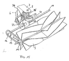
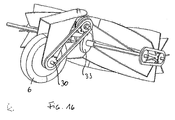
- FIGS. 15 to 20 an alternative drive for the brush roller of the sweeper is shown in different views.
- the Mitauerrad 6 is as well as in the previous embodiment by means of a holder 7 and an upper projection 8 rotatably mounted on the housing 1.
- the projection 8 is the upper end portion of an axle 34 which is inserted through an upper T-shaped sleeve 35 and with its lower end portion in a lower T-shaped Sleeve 36 is seated, through which the shaft 11 rotates.
- an axle 24 is inserted, on which a gear 26 rotatably seated, which is non-rotatably connected to a gear 27 arranged adjacent thereto.
- the gear 26 is connected via a link chain 28 with a gear 29 which is non-rotatably mounted on a driven by the Mitauerrad 6 shaft 30.
- the gear 27 is engaged with a gear 31 arranged at right angles thereto, which sits rotatably on the axis 34 and meshes with its lower teeth with a gear 33 which is non-rotatably connected to the axis 11.
- the rotation of the shaft 11 is transmitted via a non-rotatably connected thereto gear 12 and a link chain 13 to the gear 14, with which the brush roller 3 is rotatably connected.
Landscapes
- Engineering & Computer Science (AREA)
- Mechanical Engineering (AREA)
- Architecture (AREA)
- Civil Engineering (AREA)
- Structural Engineering (AREA)
- Transportation (AREA)
- Brushes (AREA)
- Toys (AREA)
- Motorcycle And Bicycle Frame (AREA)
- Mechanical Control Devices (AREA)
Description
- Die Erfindung betrifft ein Kinderfahrzeug gemäß dem Oberbegriff des Patentanspruchs 1. Bei dem Kinderfahrzeug handelt es sich vorzugsweise um ein Tretfahrzeug, wobei die Erfindung aber auch auf motorgetriebene Kinderfahrzeuge anwendbar ist.
- Spielfahrzeuge der betrachteten Art, bei denen ein Kind auf dem Tretfahrzeug oder motorgetriebenen Fahrzeug sitzt, haben einen erhöhten Spielwert, wenn sie mit Zubehör ausgerüstet sind, mit dem über das eigentliche Fahren mit dem Fahrzeug hinaus bestimmte Aufgaben oder "Arbeiten" auf spielerische Weise ausgeführt werden können. Ein Beispiel hierfür ist ein Kindertretfahrzeug mit einer an zwei Armen gehaltenen Ladeschaufel, die in einer abgesenkten Position beispielsweise mit Sand beladen werden kann, um anschließend nach oben verschwenkt und in der angehobenen Position verriegelt zu werden, so dass das Tretfahrzeug nun mit der Ladung zu seinem Bestimmungsort gefahren werden kann, wo mittels eines Kippmechanismus die Ladeschaufel verschwenkt und die Sandladung ausgeschüttet werden kann. Ein weiteres Beispiel ist ein Kindertretfahrzeug, das mit einem Schneeräumschild versehen ist, mit dem ein Kind u.a. den Gehweg vor einer Haustür oder eine Garagenzufahrt von Schnee räumen kann, wodurch das Fahren mit dem Tretfahrzeug im Schnee interessant ist.
- Das Spielzeug-Straßenreinigungsgerät der
DE 81 02 981 U1 , die als nächstliegender Stand der Technik angesehen wird, enthält in Fahrtrichtung vor der Bürstenwalze zwei in Längsschlitzen des Gehäuses gelagerte Laufräder, die beim Fahren des Gerätes mit ihren am Umfang angeordneten Gummiringen in einem reibenden Kontakt mit Längsrillen an äußeren Wellenabschnitten der rotierbaren Bürste gelangen, wodurch die Bürstenwelle mitgenommen werden und somit die Bürste in Rotation versetzt wird. Diese Laufräder sind nicht um vertikale Achsen schwenkbar gelagert, so dass sie beim Kurvenfahren über den Boden rutschen können und die Bürstenwalze dann nicht mehr antreiben. - Bei einem Spielzeugkehrwagen gemäß der
DE 873 669 treiben die beiden hinteren Laufräder eine Bürstenwalze über ein Getriebe an. Einen Bürstenantrieb über Laufräder von Spielzeug-Kehrwagen offenbaren auch dieDE 874 261 B sowie dieUS 4 917 648 A . - Der vorliegenden Erfindung liegt die Aufgabe zugrunde, ein Kinderfahrzeug anzugeben, dessen Spielwert dadurch erhöht ist, dass es für neue Verwendungszwecke einsetzbar ist.
- Diese Aufgabe wird erfindungsgemäß durch die Merkmale des Patentanspruchs 1 gelöst.
- Vorteilhafte Ausgestaltungen sind in den Unteransprüchen gekennzeichnet.
- Die Erfindung sieht vor, dass das Kinderfahrzeug mit einem Kehrgerät verbindbar ist, das mit wenigstens einer Bürstenwalze versehen ist, Das Kehrgerät ist dabei mit dem Kinderfahrzeug lösbar verbunden, so dass das Kehrgerät bei Bedarf leicht an dem Kinderfahrzeug anbringbar und wieder abnehmbar ist.
- Durch die Anbringung des Kehrgerätes ist der Spielwert des Kinderfahrzeuges erheblich erhöht, da das Kind hiermit die Möglichkeit erhält, auf spielerische Weise eine interessante und dabei in vielen Fällen nützliche Aufgabe zu erfüllen. Beispielsweise kann das Kind mit seinem Fahrzeug in der Wohnung den Boden kehren oder außerhalb des Hauses z.B. den Gehweg vor der Haustür oder eine Garagenzufahrt von loser Erde, Sand, Splitt oder dergleichen befreien.
- Das Kehrgerät wird vorzugsweise vorne an dem Kinderfahrzeug befestigt, wozu das Kinderfahrzeug mit einem vorstehenden Kupplungsmaul versehen sein kann, in das das Kehrgerät mit einem entsprechend gestalteten Ansatz eingreift, wobei dieser Eingriff beispielsweise durch einen von oben nach unten durchgesteckten Bolzen aufrecht erhalten wird. Dabei liegt es im Rahmen der Erfindung, dass das Kehrgerät statt dessen hinten an dem Kinderfahrzeug anbringbar ist.
Mit Vorteil ist vorgesehen, dass das Kehrgerät so an dem Kinderfahrzeug befestigt wird, dass es in der horizontalen Ebene nicht-schwenkbar gegenüber dem Kinderfahrzeug ist. D.h. das Kinderfahrzeug und das Kehrgerät bilden eine lang gestreckte, starre Einheit, so dass beim Kurvenfahren das Kehrgerät gemeinsam mit dem Kinderfahrzeug die gekrümmte Bahn durchfährt. - Mit besonderem Vorteil wird vorgeschlagen, dass das Kehrgerät über einen Adapter mit dem Kinderfahrzeug verbindbar ist, wobei der Adapter bevorzugt an dem oben erwähnten Kupplungsmaul des Kinderfahrzeugs befestigt ist. Auch hierbei ist die lösbare Anbringung bevorzugt vorne an dem Kinderfahrzeug vorgesehen, ohne dass die Erfindung hierauf beschränkt ist.
- Der Adapter dient dazu, dass das Kehrgerät aus der funktionsfähigen Lage, in der es mit seinen Rollen oder Rädern auf dem Boden aufliegt, anhebbar ist, wobei hierbei das gesamte Kehrgerät schräg nach oben angehoben wird. Der Adapter hat dabei Führungsbahnen, in die Zapfen eingreifen, die sich an einem Bügel befinden, der starr an dem Gehäuse des Kehrgerätes befestigt ist. Beim Anheben des Kehrgerätes werden die Zapfen des Bügels in den Führungsbahnen nach oben bewegt und in der oberen Endstellung verriegelt, in der das Kehrgerät vom Boden abgehoben ist.
- Wie bereits oben erwähnt, enthält das Kehrgerät wenigstens eine Bürstenwalze, die um eine horizontale, in Querrichtung des Kehrgeräts verlaufende Achse gedreht wird. Dabei liegt es im Rahmen der Erfindung, dass beispielsweise auch zwei Bürsten vorgesehen sein können, die in Querrichtung nebeneinander liegend um vertikale Achsen gegenläufig rotieren.
- Der Antriebsmechanismus enthält erfindungsgemäß ein Mitnehmerrad, das in der funktionsfähigen Lage des Kehrgerätes auf dem Boden aufliegt und damit bei der Fahrt des Kinderfahrzeugs gedreht wird. An dem Mitnehmerrad liegt in einer Ausführungsform ein weiteres Rad an, das vorzugsweise die Form eines Kugelabschnitts hat und mit seiner balligen Lauffläche stets an das Mitnehmerrad angedrückt ist. Dieses von dem Mitnehmerrad angetriebene Rad, das auch als Kugelrad bezeichnet werden kann, ist drehfest mit einer Antriebsachse für die Bürstenwalze verbunden. Die Antriebsachse und die Achse der Bürstenwalze sind antriebsmäßig z.B. über eine Gliederkette verbunden, die in Eingriff mit den beiden Zahnrädern der Antriebsachse und der Achse der Bürstenwalze steht. Es können auch andere Mittel eingesetzt werden, um die Drehung der Antriebsachse auf die Achse der Bürstenwalze zu übertragen, beispielsweise Zahnriemen, 0-Ringe oder ein Zahnradgetriebe.
- Das Kugelrad hat vorzugsweise eine Lauffläche mit einem hohen Reibungskoeffizienten und besteht beispielsweise aus EVA. Das Kugelrad oder das Mitnehmerrad kann bzw. können eine Oberflächenstruktur aufweisen, die dazu beiträgt, dass die Drehung des Mitnehmerrades ohne Gleiten auf das Kugelrad übertragen wird.
- Weiter ist erfindungsgemäß vorgesehen, dass das Mitnehmerrad um eine senkrechte Achse drehbar gelagert ist. Dabei befindet sich die senkrechte Achse mittig über der Antriebsachse, indem sie an dieser Stelle an der Gehäusewand befestigt ist. Diese Ausbildung hat zur Folge, dass bei Lenkbewegungen des Kinderfahrzeugs das Mitnehmerrad entsprechend einlenkt, wobei stets der Kontakt mit dem vorzugsweise angeordneten Kugelrad der Antriebsachse aufrecht erhalten wird. Hierdurch ist verhindert, dass beim Kurvenfahren des Fahrzeugs mit der Kehrmaschine das Mitnehmerrad nur über den Boden rutscht und die Bürstenwalze nicht mehr antreibt.
- Das Kehrgerät enthält zudem vorzugsweise einen Auffangbehälter, der (bei der bevorzugten Anbringung des Kehrgerätes am vorderen Ende des Kinderfahrzeugs) am vorderen Endbereich des Gehäuses des Kehrgerätes lösbar befestigt ist. Die Bürstenwalze dreht sich am Boden in der Fahrrichtung des Kinderfahrzeugs und des Kehrgerätes und fördert so das Kehrgut nach vorne in den Auffangbehälter.
- Am vorderen Endbereich des Gehäuses des Kehrgerätes sind nach einem weiteren Vorschlag der Erfindung zwei seitlich beabstandete Laufrollen befestigt, die um vertikale Achsen drehbar sind. Das Gehäuse des Kehrgerätes liegt damit auf diesen vorderen Lenkrollen und auf dem im hinteren Bereich des Kehrgerätes angeordneten Mitnehmerrad auf, wobei durch diese Drei-Punkt-Lagerung der Abstand der Bürstenwalze zum Boden in der funktionsfähigen Lage des Kehrgerätes stets konstant bleibt.
- Das Gehäuse des Kehrgerätes und sein Auffangbehälter bestehen zweckmäßigerweise aus Kunststoff, was auch auf den bevorzugt vorgesehenen Adapter zutrifft.
- Weitere Einzelheiten der Erfindung ergeben sich aus der nachfolgenden Beschreibung einer bevorzugten Ausführungsform des Kehrgerätes sowie anhand der Zeichnungen. Dabei zeigen:
- Figur 1
- eine Seitenansicht einer Ausführungsform des Kehrgerätes mit einem Adapter;
- Figur 2
- eine Vorderansicht des Kehrgerätes gemäß
Figur 1 ; - Figur 3
- eine perspektivische Aufsicht auf das Kehrgerät gemäß
Figur 1 ; - Figur 4
- einen Schnitt entlang der Linie A-A in
Figur 2 ; - Figur 5
- eine Seitenansicht der Antriebsanordnung für die Bürstenwalze des Kehrgerätes;
- Figur 6
- einen Schnitt entlang der Linie B-B in
Figur 5 ; - Figur 7
- eine Vorderansicht auf die Anordnung gemäß
Figur 5 von rechts; - Figur 8
- eine Aufsicht auf die Anordnung gemäß
Figur 5 ; - Figur 9
- eine perspektivische Ansicht der Anordnung gemäß
Figur 5 ; - Figur 10 bis 13
- verschiedene perspektivische Ansichten des Kehrgeräts gemäß
Figur 1 und - Figur 14
- eine Darstellung der einzelnen Bestandteile des Kehrgerätes gemäß
Figur 1 ; - Figuren 15 bis 20
- einen alternativen Antrieb mittel Kette und Zahnrädern in verschiedenen Darstellungen.
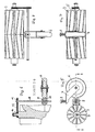
- Das Kehrgerät enthält ein Gehäuse 1, an dessen vorderen Endbereich ein Auffangbehälter 2 für Kehrgut lösbar befestigt ist. In dem Gehäuse 1 ist eine Bürstenwalze 3 angeordnet, die beim Vorwärtsfahren eines in den Figuren nicht dargestellten Kinderfahrzeugs Kehrgut in den Auffangbehälter 2 befördert. Die Bürstenwalze 3 dreht sich dabei am Boden in der Fahrtrichtung des Kinderfahrzeugs und fördert das Kehrgut nach vorne, wobei eine sich in Längsrichtung der Bürstenwalze 3 erstreckende, am Boden anliegende Lippe 4 den Eintritt des Kehrgutes in den Auffangbehälter 2 erleichtert.
- Zum Antrieb der Bürstenwalze 3, die um ihre horizontale Achse 5 drehbar ist, ist in dem Gehäuse 1 ein Mitnehmerrad 6 angeordnet, das im funktionsfähigen Zustand des Kehrgerätes am Boden anliegt. Das Mitnehmerrad 6 ist über eine Halterung 7 mit einem Stift 8 verbunden, der eine vertikale Achse bildet, um die das Mitnehmerrad 6 schwenkbar ist. Der Stift 8 ist oben an dem Gehäuse 1 des Kehrgeräts befestigt.
- An dem Mitnehmerrad 6 liegt ein weiteres Rad 9 ständig an, das eine im Querschnitt kreisbogenförmige Lauffläche 10 hat. Das Rad 9 ist drehfest mit einer Antriebsachse 11 verbunden, auf der das Rad 9 mittig sitzt.
- An einem Endabschnitt der Antriebsachse 11 ist ein Zahnrad 12 drehfest mit der Antriebsachse verbunden, über das eine Gliederkette 13 läuft, die außerdem im Eingriff mit einem Zahnrad 14 der Achse 5 der Bürstenwalze 3 steht.
- Beim Vorwärtsfahren des Kehrgerätes (nach rechts in der Darstellung der
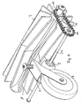
Figuren 1 und 4 ) wird stets das Mitnehmerrad 6 gedreht, wenn sich das Kehrgerät im funktionsfähigen Zustand befindet, in dem das Mitnehmerrad 6 auf dem Boden aufliegt. Beim Kurvenfahren wird das Mitnehmerrad 6 um die vertikale Achse 8 geschwenkt, die sich mittig über dem angetriebenen Rad 9 befindet. Das Rad 9 dreht über die Achse 11 das Zahnrad 12, wodurch die Bürstenwalze 3 in Drehung versetzt wird. - Oben an dem Gehäuse 1 ist ein Bügel 15 befestigt, der starr mit dem Gehäuse 1 verbunden ist. An den einander zugewandten Innenseiten der Holme des Bügels 15 befinden sich nach innen ragende Zapfen 16, die in Führungsbahnen 17 eines Adapters 18 eingreifen. Der Adapter 18 ist an einem in den Figuren nicht dargestellten vorderen Kupplungsmaul eines Kinderfahrzeugs befestigt, wobei das Kupplungsmaul zwischen horizontale Wände 19 (
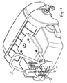
Figur 10 ) eingreift. Der Eingriff wird dadurch gesichert, dass ein (ebenfalls nicht dargestellter) Bolzen durch miteinander fluchtende Löcher 20 der Wände 19 und des Kupplungsmauls gesteckt wird. - Der Adapter liegt mit seiner in
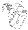
Figur 11 sichtbaren Stirnkante 21 am vorderen Ende des Kinderfahrzeugs an, so dass das Kehrgerät in der horizontalen Ebene starr mit dem Kinderfahrzeug verbunden ist. - Das Kehrgerät ist aus seiner beispielsweise in
Figur 1 dargestellten funktionsfähigen Lage, in der es mit dem Mitnehmerrad 6 und zwei am vorderen Ende des Gehäuses 1 angebrachten Lenkrollen 22 auf dem Boden aufliegt, in eine nicht-funktionsfähige Lage anhebbar, in dem der Bügel 15 als Handgriff benutzt und angehoben wird, wobei er mittels seiner Zapfen 16 in den Führungsbahnen 17 des Adapters 18 geführt wird. Das obere Zapfenpaar wird in einem Arretierabschnitt 23 der Führungsbahnen 17 fixiert. In diesem Zustand ist das gesamte Kehrgerät vom Boden abgehoben. - In den
Figuren 15 bis 20 ist ein alternativer Antrieb für die Bürstenwalze des Kehrgerätes in verschiedenen Ansichten dargestellt. Das Mitnehmerrad 6 ist ebenso wie bei der vorigen Ausführungsform mittels einer Halterung 7 und einem oberen Vorsprung 8 drehbar am Gehäuse 1 befestigt. Der Vorsprung 8 ist der obere Endabschnitt einer Achse 34, die durch eine obere T-förmige Hülse 35 hindurchgesteckt ist und mit ihrem unteren Endabschnitt in einer unteren T-förmigen Hülse 36 sitzt, durch die die Welle 11 drehbar verläuft. In den horizontalem Teil der Hülse 35 ist ein Achsstück 24 eingesteckt, auf dem ein Zahnrad 26 drehbar sitzt, das drehfest mit einem daneben angeordneten Zahnrad 27 verbunden ist. Das Zahnrad 26 ist über eine Gliederkette 28 mit einem Zahnrad 29 verbunden, das drehfest auf einer von dem Mitnehmerrad 6 angetriebenen Welle 30 sitzt. - Das Zahnrad 27 steht im Eingriff mit einem rechtwinklig dazu angeordneten Zahnrad 31, das drehbar auf der Achse 34 sitzt und mit seiner unteren Verzahnung mit einem Zahnrad 33 kämmt, das drehfest mit der Achse 11 verbunden ist. Wie bei der obigen Ausführungsform wird die Drehung der Achse 11 über ein drehfest damit verbundenes Zahnrad 12 und eine Gliederkette 13 auf das Zahnrad 14 übertragen, mit der die Bürstenwalze 3 drehfest verbunden ist.
- Beim Kurvenfahren wird - ebenso wie bei der oben beschriebenen Ausführungsform - das Mitnehmerrad 6 mit der Halterung 7 um die Achse 8 verschwenkt, wobei die Zahnräder 29, 26 und 27 mit der Gliederkette 28 dieser Schwenkbewegung folgen. Das Zahnrad 27 läuft auf dem Zahnrad 31 entsprechend ab. Wenn die Welle 30 des Mitnehmerrades 6 beim Ablaufen des Mitnehmerrades 6 am Boden gedreht wird, dreht das Zahnrad 29 über die Gliederkette 28 das Zahnrad 26 und damit das Zahnrad 27, das über das Zwischenrad 31 das Zahnrad 33 und damit das Zahnrad 12 dreht, das seinerseits über die Gliederkette 13 die Bürstenwalze 3 rotieren lässt.
- Es wird betont, dass die Erfindung nicht auf die beschriebenen und dargestellten Ausführungsformen beschränkt ist. Vielmehr sind alle offenbarten Merkmale auf jede Weise einzeln miteinander kombinierbar.
Claims (12)
- Kinderfahrzeug, insbesondere Tretfahrzeug, mit einem mit wenigstens einer um eine horizontale Achse rotierbaren Bürste versehenen Kehrgerät, das mit dem Kinderfahrzeug lösbar verbindbar ist,
dadurch gekennzeichnet,
dass zum Antrieb der Bürstenwalze ein Mitnehmerrad (6) angeordnet ist, das in der funktionsfähigen Lage des Kehrgerätes am Boden anliegt und mit einer Antriebsachse (11) antriebsmäßig gekoppelt ist, die ihrerseits mit der Achse (5) der Bürstenwalze (3) antriebsmäßig gekoppelt ist, und dass das Mitnehmerrad (6) um eine senkrechte Achse (8) drehbar gelagert ist, die mittig über der Antriebsachse (11) angeordnet ist. - Kinderfahrzeug nach Anspruch 1,
dadurch gekennzeichnet,
dass das Kehrgerät an einem Kupplungsmaul des Kinderfahrzeugs befestigbar ist, wobei die Befestigung in der horizontalen Ebene starr ist. - Kinderfahrzeug nach Anspruch 2,
dadurch gekennzeichnet,
dass sich das Kupplungsmaul vorne an dem Kinderfahrzeug befindet. - Kinderfahrzeug nach einem der Ansprüche 1 bis 3,
dadurch gekennzeichnet,
dass das Kehrgerät über einen Adapter (8) an dem Kinderfahrzeug befestigbar ist. - Kinderfahrzeug nach Anspruch 4,
dadurch gekennzeichnet,
dass das Kehrgerät aus einer funktionsfähigen Lage in eine vom Boden beabstandete Lage anhebbar ist. - Kinderfahrzeug nach Anspruch 1,
dadurch gekennzeichnet,
dass an dem Mitnehmerrad (6) ein Rad (9) mit kreisbogenförmiger Lauffläche anliegt, das drehfest mit der Antriebsachse (11) verbunden ist. - Kinderfahrzeug nach Anspruch 1,
dadurch gekennzeichnet,
dass die antriebsmäßige Koppelung der Bürstenwalze über eine GliederKette (13) erfolgt, die in Zahnräder (12,14) der Antriebsachse (11) und der Achse (5) der Bürstenwalze (3) eingreift. - Kinderfahrzeug nach Anspruch 6,
dadurch gekennzeichnet,
dass die senkrechte Achse (8) mittig über dem Rad (9) angeordnet ist. - Kinderfahrzeug nach Anspruch 1,
dadurch gekennzeichnet,
dass das Mitnehmerrad (6) über Zahnräder (26,29,27,31,33) und eine Gliederkette (28) mit der Antriebsachse (11) verbunden ist. - Kinderfahrzeug nach Anspruch 9,
dadurch gekennzeichnet,
dass die senkrechte Achse (8) mittels einer Hülse (36) an der Antriebsachse (11) gehalten ist. - Kinderfahrzeug nach einem der Ansprüche 1 bis 10,
ferner gekennzeichnet durch
einen Auffangbehälter (2), der am vorderen Endbereich des Gehäuses (1) des Kehrgerätes lösbar befestigt ist. - Kinderfahrzeug nach einem der Ansprüche 1 bis 11,
dadurch gekennzeichnet,
dass am vorderen Endbereich des Gehäuses (1) des Kehrgerätes zwei seitlich beabstandete Lenkrollen (22) befestigt sind.
Priority Applications (1)
| Application Number | Priority Date | Filing Date | Title |
|---|---|---|---|
| PL09001273T PL2088067T3 (pl) | 2008-02-07 | 2009-01-30 | Pojazd dziecięcy, zwłaszcza pojazd pedałowy |
Applications Claiming Priority (1)
| Application Number | Priority Date | Filing Date | Title |
|---|---|---|---|
| DE102008007895A DE102008007895B4 (de) | 2008-02-07 | 2008-02-07 | Kinderfahrzeug, insbesondere Tretfahrzeug |
Publications (3)
| Publication Number | Publication Date |
|---|---|
| EP2088067A2 EP2088067A2 (de) | 2009-08-12 |
| EP2088067A3 EP2088067A3 (de) | 2012-02-22 |
| EP2088067B1 true EP2088067B1 (de) | 2013-01-09 |
Family
ID=40602479
Family Applications (1)
| Application Number | Title | Priority Date | Filing Date |
|---|---|---|---|
| EP09001273A Active EP2088067B1 (de) | 2008-02-07 | 2009-01-30 | Kinderfahrzeug, insbesondere Tretfahrzeug |
Country Status (6)
| Country | Link |
|---|---|
| US (1) | US7967317B2 (de) |
| EP (1) | EP2088067B1 (de) |
| DE (1) | DE102008007895B4 (de) |
| DK (1) | DK2088067T3 (de) |
| ES (1) | ES2403534T3 (de) |
| PL (1) | PL2088067T3 (de) |
Families Citing this family (12)
| Publication number | Priority date | Publication date | Assignee | Title |
|---|---|---|---|---|
| US9119463B2 (en) | 2011-10-03 | 2015-09-01 | Pentair Water Pool & Spa, Inc. | Pool cleaner with detachable scrubber assembly |
| DE102012000329B4 (de) * | 2012-01-11 | 2015-12-24 | Franz Schneider Gmbh & Co. Kg | Anhänger für ein Kinderfahrzeug |
| DE102012022638B4 (de) | 2012-11-20 | 2017-05-24 | Franz Schneider Gmbh & Co. Kg | Kehrgerät für ein Kinderfahrzeug, insbesondere für ein Tretfahrzeug |
| US9643672B2 (en) * | 2014-06-24 | 2017-05-09 | Kettler International, Inc. | Child's ride-on toy with removable cart |
| CN104960608B (zh) * | 2015-05-29 | 2018-03-13 | 上海理工大学 | 一种兼具打扫功能的电动玩具车 |
| DE102015109398A1 (de) * | 2015-06-12 | 2016-12-15 | Kai Drecoll | Kinderfahrzeug |
| US10265637B2 (en) * | 2017-03-14 | 2019-04-23 | Eliezer Leider | Ride-on and push toy for storage and picking up small objects on plane surface |
| CN107988970A (zh) * | 2017-12-04 | 2018-05-04 | 刘城 | 一种道路施工用伸缩缝清洁装置 |
| AU2019315328B2 (en) * | 2018-08-01 | 2023-07-20 | DNA Global Industries Pty Ltd | Ride on toy |
| CN112930560A (zh) * | 2019-08-27 | 2021-06-08 | 山东英才学院 | 一种可移动式雷达感应儿童学习机 |
| CN112519931B (zh) * | 2020-11-23 | 2022-02-01 | 山东人人出行科技有限公司 | 一种供共享单车使用的车筐 |
| US12397241B1 (en) * | 2025-03-25 | 2025-08-26 | Jiayang Huang | Children's car with cleaning function |
Family Cites Families (18)
| Publication number | Priority date | Publication date | Assignee | Title |
|---|---|---|---|---|
| US581196A (en) * | 1897-04-20 | conselyea | ||
| US810547A (en) * | 1904-06-06 | 1906-01-23 | Robert Charles Menzies | Self-loading cart. |
| US1463707A (en) * | 1920-05-04 | 1923-07-31 | Wesley N Koger | Street-cleaning machine |
| US2345460A (en) * | 1942-11-07 | 1944-03-28 | Patrick E E Coderre | Snowplow attachment for toys |
| DE873669C (de) * | 1950-11-28 | 1953-04-16 | Adolf Buettner | Spielzeugkehrwagen |
| US2703897A (en) * | 1951-05-26 | 1955-03-15 | Malm Henry | Dual one-way drive carpet sweeper |
| DE874261C (de) * | 1951-08-23 | 1953-04-23 | Adolf Buettner | Spielzeug-Kehrwagen |
| US3197918A (en) * | 1962-02-20 | 1965-08-03 | Coggeshall Charles Henry | Animated wheeled eating toy |
| US3233274A (en) * | 1963-01-28 | 1966-02-08 | Tennant Co G H | Sweeping machine dust separator apparatus |
| US3354489A (en) * | 1966-03-16 | 1967-11-28 | Stanley Western Corp | Sweeper attachment for lift trucks |
| US3862538A (en) * | 1972-03-14 | 1975-01-28 | James A Henson | Nut harvesting machine |
| US3947912A (en) * | 1974-09-13 | 1976-04-06 | Abraham Michaels | Manually operated sweeper |
| US4031659A (en) * | 1975-11-10 | 1977-06-28 | Marvin Glass & Associates | Toy pick-up vehicle |
| DE8102981U1 (de) * | 1981-02-05 | 1981-06-19 | bruder Spielwaren, Inh. Heinz Bruder, 8510 Fürth | Spielzeug-strassenreinigungsgeraet |
| US4393537A (en) * | 1981-07-13 | 1983-07-19 | All Temp Engineering Inc. | Power broom with auger and vacuum debris conveyor |
| US4917648A (en) * | 1988-08-09 | 1990-04-17 | Hartje Robert A | Toy sanitation truck |
| US5208935A (en) * | 1991-07-16 | 1993-05-11 | Bissell Inc. | Carpet sweeper |
| US7134161B2 (en) * | 2004-01-05 | 2006-11-14 | Telmo Olavo Campos | Mechanical broom |
-
2008
- 2008-02-07 DE DE102008007895A patent/DE102008007895B4/de not_active Expired - Fee Related
-
2009
- 2009-01-30 DK DK09001273.3T patent/DK2088067T3/da active
- 2009-01-30 ES ES09001273T patent/ES2403534T3/es active Active
- 2009-01-30 PL PL09001273T patent/PL2088067T3/pl unknown
- 2009-01-30 EP EP09001273A patent/EP2088067B1/de active Active
- 2009-02-06 US US12/367,109 patent/US7967317B2/en active Active
Also Published As
| Publication number | Publication date |
|---|---|
| DE102008007895A1 (de) | 2009-08-20 |
| US20090203293A1 (en) | 2009-08-13 |
| ES2403534T3 (es) | 2013-05-20 |
| PL2088067T3 (pl) | 2013-08-30 |
| EP2088067A3 (de) | 2012-02-22 |
| US7967317B2 (en) | 2011-06-28 |
| EP2088067A2 (de) | 2009-08-12 |
| DK2088067T3 (da) | 2013-04-15 |
| DE102008007895B4 (de) | 2013-06-20 |
Similar Documents
| Publication | Publication Date | Title |
|---|---|---|
| EP2088067B1 (de) | Kinderfahrzeug, insbesondere Tretfahrzeug | |
| EP2743038B1 (de) | Anordnung zur Überwindung eines Verfahrhindernisses | |
| DE69602095T2 (de) | Sitzeinrichtung für deichselgesteuerte maschine | |
| EP1893153B1 (de) | Rollstuhl mit mittenradantrieb | |
| CH713464B1 (de) | Fahrzeug mit Mittenradantrieb, insbesondere Rollstuhl oder Aufrichtrollstuhl. | |
| DE29812994U1 (de) | Verwandelbares Raupenspielzeugfahrzeug | |
| EP1241298B1 (de) | Fahrzeug, insbesondere zur Strandreinigung | |
| EP2733262B1 (de) | Kehrgerät für ein Kinderfahrzeug, insbesondere für ein Tretfahrzeug | |
| EP0151982A2 (de) | Selbstfahrender Bodentransporter | |
| DE102012101109B4 (de) | Geräteträger für Reinigungsgeräte mit Mittenantrieb zum Frontanbau | |
| DE1482172A1 (de) | Heuwerbungsmaschine | |
| DE2460584B2 (de) | Kehrmaschine | |
| DE29817336U1 (de) | Elektro-Rollstuhl | |
| DE1837772U (de) | Hackmaschine, insbesondere zur entfernung des unkrauts von strassenrandstreifen, eisenbahnboeschungen od. dgl. | |
| DE102014006391A1 (de) | Kehrmaschine | |
| EP1319758A2 (de) | Bodenreinigungsmaschine mit Seitenbürste | |
| EP1362772B1 (de) | Fahrzeug zum Umsetzen von Kompostmieten | |
| DE19853351A1 (de) | Spielsand-Reinigungsgerät | |
| DE3107840A1 (de) | "vorbau-strassenkehrmaschine" | |
| DE4431182A1 (de) | Pflegegerät mit höhenverstellbarem Walzenträger | |
| EP0911010A2 (de) | Kupplungsvorrichtung zum wahlweisen Ankuppeln einer Antriebseinheit an einen Rollstuhl | |
| DE1921891A1 (de) | Reinigungsvorrichtung fuer Lastkraftwagen | |
| DE102019107272B4 (de) | Rollator | |
| DE3302014A1 (de) | Golfwagen mit batteriebetriebenem hilfsantrieb | |
| DE7538290U (de) | Motor-kehrfahrzeug |
Legal Events
| Date | Code | Title | Description |
|---|---|---|---|
| PUAI | Public reference made under article 153(3) epc to a published international application that has entered the european phase |
Free format text: ORIGINAL CODE: 0009012 |
|
| AK | Designated contracting states |
Kind code of ref document: A2 Designated state(s): AT BE BG CH CY CZ DE DK EE ES FI FR GB GR HR HU IE IS IT LI LT LU LV MC MK MT NL NO PL PT RO SE SI SK TR |
|
| AX | Request for extension of the european patent |
Extension state: AL BA RS |
|
| PUAL | Search report despatched |
Free format text: ORIGINAL CODE: 0009013 |
|
| RIC1 | Information provided on ipc code assigned before grant |
Ipc: B62K 27/00 20060101ALI20120110BHEP Ipc: B62K 9/00 20060101AFI20120110BHEP Ipc: E01H 1/02 20060101ALI20120110BHEP Ipc: B62K 13/00 20060101ALI20120110BHEP Ipc: E04H 1/02 20060101ALI20120110BHEP |
|
| AK | Designated contracting states |
Kind code of ref document: A3 Designated state(s): AT BE BG CH CY CZ DE DK EE ES FI FR GB GR HR HU IE IS IT LI LT LU LV MC MK MT NL NO PL PT RO SE SI SK TR |
|
| AX | Request for extension of the european patent |
Extension state: AL BA RS |
|
| RIC1 | Information provided on ipc code assigned before grant |
Ipc: E01H 1/02 20060101ALI20120113BHEP Ipc: B62K 13/00 20060101ALI20120113BHEP Ipc: B62K 9/00 20060101AFI20120113BHEP Ipc: E04H 1/02 20060101ALI20120113BHEP Ipc: B62K 27/00 20060101ALI20120113BHEP |
|
| 17P | Request for examination filed |
Effective date: 20120215 |
|
| GRAP | Despatch of communication of intention to grant a patent |
Free format text: ORIGINAL CODE: EPIDOSNIGR1 |
|
| AKX | Designation fees paid |
Designated state(s): AT BE BG CH CY CZ DE DK EE ES FI FR GB GR HR HU IE IS IT LI LT LU LV MC MK MT NL NO PL PT RO SE SI SK TR |
|
| GRAS | Grant fee paid |
Free format text: ORIGINAL CODE: EPIDOSNIGR3 |
|
| GRAA | (expected) grant |
Free format text: ORIGINAL CODE: 0009210 |
|
| AK | Designated contracting states |
Kind code of ref document: B1 Designated state(s): AT BE BG CH CY CZ DE DK EE ES FI FR GB GR HR HU IE IS IT LI LT LU LV MC MK MT NL NO PL PT RO SE SI SK TR |
|
| REG | Reference to a national code |
Ref country code: GB Ref legal event code: FG4D Free format text: NOT ENGLISH |
|
| REG | Reference to a national code |
Ref country code: CH Ref legal event code: EP Ref country code: AT Ref legal event code: REF Ref document number: 592567 Country of ref document: AT Kind code of ref document: T Effective date: 20130115 |
|
| REG | Reference to a national code |
Ref country code: IE Ref legal event code: FG4D Free format text: LANGUAGE OF EP DOCUMENT: GERMAN |
|
| REG | Reference to a national code |
Ref country code: DE Ref legal event code: R096 Ref document number: 502009005920 Country of ref document: DE Effective date: 20130307 |
|
| REG | Reference to a national code |
Ref country code: CH Ref legal event code: NV Representative=s name: KIRKER AND CIE S.A., CH |
|
| REG | Reference to a national code |
Ref country code: DK Ref legal event code: T3 |
|
| REG | Reference to a national code |
Ref country code: SE Ref legal event code: TRGR |
|
| REG | Reference to a national code |
Ref country code: ES Ref legal event code: FG2A Ref document number: 2403534 Country of ref document: ES Kind code of ref document: T3 Effective date: 20130520 |
|
| PG25 | Lapsed in a contracting state [announced via postgrant information from national office to epo] |
Ref country code: SI Free format text: LAPSE BECAUSE OF FAILURE TO SUBMIT A TRANSLATION OF THE DESCRIPTION OR TO PAY THE FEE WITHIN THE PRESCRIBED TIME-LIMIT Effective date: 20130109 |
|
| REG | Reference to a national code |
Ref country code: NL Ref legal event code: T3 |
|
| REG | Reference to a national code |
Ref country code: GR Ref legal event code: EP Ref document number: 20130400685 Country of ref document: GR Effective date: 20130517 |
|
| REG | Reference to a national code |
Ref country code: LT Ref legal event code: MG4D |
|
| REG | Reference to a national code |
Ref country code: SK Ref legal event code: T3 Ref document number: E 13885 Country of ref document: SK |
|
| PG25 | Lapsed in a contracting state [announced via postgrant information from national office to epo] |
Ref country code: LT Free format text: LAPSE BECAUSE OF FAILURE TO SUBMIT A TRANSLATION OF THE DESCRIPTION OR TO PAY THE FEE WITHIN THE PRESCRIBED TIME-LIMIT Effective date: 20130109 Ref country code: BG Free format text: LAPSE BECAUSE OF FAILURE TO SUBMIT A TRANSLATION OF THE DESCRIPTION OR TO PAY THE FEE WITHIN THE PRESCRIBED TIME-LIMIT Effective date: 20130409 Ref country code: NO Free format text: LAPSE BECAUSE OF FAILURE TO SUBMIT A TRANSLATION OF THE DESCRIPTION OR TO PAY THE FEE WITHIN THE PRESCRIBED TIME-LIMIT Effective date: 20130409 Ref country code: IS Free format text: LAPSE BECAUSE OF FAILURE TO SUBMIT A TRANSLATION OF THE DESCRIPTION OR TO PAY THE FEE WITHIN THE PRESCRIBED TIME-LIMIT Effective date: 20130509 |
|
| PG25 | Lapsed in a contracting state [announced via postgrant information from national office to epo] |
Ref country code: PT Free format text: LAPSE BECAUSE OF FAILURE TO SUBMIT A TRANSLATION OF THE DESCRIPTION OR TO PAY THE FEE WITHIN THE PRESCRIBED TIME-LIMIT Effective date: 20130509 Ref country code: LV Free format text: LAPSE BECAUSE OF FAILURE TO SUBMIT A TRANSLATION OF THE DESCRIPTION OR TO PAY THE FEE WITHIN THE PRESCRIBED TIME-LIMIT Effective date: 20130109 Ref country code: MC Free format text: LAPSE BECAUSE OF NON-PAYMENT OF DUE FEES Effective date: 20130131 |
|
| REG | Reference to a national code |
Ref country code: PL Ref legal event code: T3 |
|
| PG25 | Lapsed in a contracting state [announced via postgrant information from national office to epo] |
Ref country code: HR Free format text: LAPSE BECAUSE OF FAILURE TO SUBMIT A TRANSLATION OF THE DESCRIPTION OR TO PAY THE FEE WITHIN THE PRESCRIBED TIME-LIMIT Effective date: 20130109 |
|
| PG25 | Lapsed in a contracting state [announced via postgrant information from national office to epo] |
Ref country code: RO Free format text: LAPSE BECAUSE OF FAILURE TO SUBMIT A TRANSLATION OF THE DESCRIPTION OR TO PAY THE FEE WITHIN THE PRESCRIBED TIME-LIMIT Effective date: 20130109 Ref country code: EE Free format text: LAPSE BECAUSE OF FAILURE TO SUBMIT A TRANSLATION OF THE DESCRIPTION OR TO PAY THE FEE WITHIN THE PRESCRIBED TIME-LIMIT Effective date: 20130109 |
|
| PLBE | No opposition filed within time limit |
Free format text: ORIGINAL CODE: 0009261 |
|
| STAA | Information on the status of an ep patent application or granted ep patent |
Free format text: STATUS: NO OPPOSITION FILED WITHIN TIME LIMIT |
|
| PG25 | Lapsed in a contracting state [announced via postgrant information from national office to epo] |
Ref country code: CY Free format text: LAPSE BECAUSE OF FAILURE TO SUBMIT A TRANSLATION OF THE DESCRIPTION OR TO PAY THE FEE WITHIN THE PRESCRIBED TIME-LIMIT Effective date: 20130109 |
|
| 26N | No opposition filed |
Effective date: 20131010 |
|
| REG | Reference to a national code |
Ref country code: DE Ref legal event code: R097 Ref document number: 502009005920 Country of ref document: DE Effective date: 20131010 |
|
| PG25 | Lapsed in a contracting state [announced via postgrant information from national office to epo] |
Ref country code: MT Free format text: LAPSE BECAUSE OF FAILURE TO SUBMIT A TRANSLATION OF THE DESCRIPTION OR TO PAY THE FEE WITHIN THE PRESCRIBED TIME-LIMIT Effective date: 20130109 |
|
| PG25 | Lapsed in a contracting state [announced via postgrant information from national office to epo] |
Ref country code: MK Free format text: LAPSE BECAUSE OF FAILURE TO SUBMIT A TRANSLATION OF THE DESCRIPTION OR TO PAY THE FEE WITHIN THE PRESCRIBED TIME-LIMIT Effective date: 20130109 Ref country code: HU Free format text: LAPSE BECAUSE OF FAILURE TO SUBMIT A TRANSLATION OF THE DESCRIPTION OR TO PAY THE FEE WITHIN THE PRESCRIBED TIME-LIMIT; INVALID AB INITIO Effective date: 20090130 |
|
| REG | Reference to a national code |
Ref country code: FR Ref legal event code: PLFP Year of fee payment: 8 |
|
| REG | Reference to a national code |
Ref country code: FR Ref legal event code: PLFP Year of fee payment: 9 |
|
| REG | Reference to a national code |
Ref country code: FR Ref legal event code: PLFP Year of fee payment: 10 |
|
| PGFP | Annual fee paid to national office [announced via postgrant information from national office to epo] |
Ref country code: LU Payment date: 20180108 Year of fee payment: 10 |
|
| PGFP | Annual fee paid to national office [announced via postgrant information from national office to epo] |
Ref country code: DK Payment date: 20180116 Year of fee payment: 10 Ref country code: FI Payment date: 20180103 Year of fee payment: 10 Ref country code: ES Payment date: 20180202 Year of fee payment: 10 Ref country code: GB Payment date: 20180124 Year of fee payment: 10 |
|
| PGFP | Annual fee paid to national office [announced via postgrant information from national office to epo] |
Ref country code: PL Payment date: 20180104 Year of fee payment: 10 Ref country code: IE Payment date: 20180116 Year of fee payment: 10 Ref country code: GR Payment date: 20180124 Year of fee payment: 10 Ref country code: IT Payment date: 20180131 Year of fee payment: 10 Ref country code: TR Payment date: 20180108 Year of fee payment: 10 Ref country code: SK Payment date: 20180111 Year of fee payment: 10 Ref country code: SE Payment date: 20180213 Year of fee payment: 10 Ref country code: BE Payment date: 20180119 Year of fee payment: 10 |
|
| PGFP | Annual fee paid to national office [announced via postgrant information from national office to epo] |
Ref country code: PL Payment date: 20190123 Year of fee payment: 10 Ref country code: CZ Payment date: 20190109 Year of fee payment: 11 |
|
| PGFP | Annual fee paid to national office [announced via postgrant information from national office to epo] |
Ref country code: AT Payment date: 20190128 Year of fee payment: 11 |
|
| REG | Reference to a national code |
Ref country code: DK Ref legal event code: EBP Effective date: 20190131 |
|
| GBPC | Gb: european patent ceased through non-payment of renewal fee |
Effective date: 20190130 |
|
| PG25 | Lapsed in a contracting state [announced via postgrant information from national office to epo] |
Ref country code: LU Free format text: LAPSE BECAUSE OF NON-PAYMENT OF DUE FEES Effective date: 20190130 |
|
| REG | Reference to a national code |
Ref country code: SK Ref legal event code: MM4A Ref document number: E 13885 Country of ref document: SK Effective date: 20190130 |
|
| REG | Reference to a national code |
Ref country code: BE Ref legal event code: MM Effective date: 20190131 |
|
| REG | Reference to a national code |
Ref country code: IE Ref legal event code: MM4A |
|
| PG25 | Lapsed in a contracting state [announced via postgrant information from national office to epo] |
Ref country code: SE Free format text: LAPSE BECAUSE OF NON-PAYMENT OF DUE FEES Effective date: 20190131 Ref country code: FI Free format text: LAPSE BECAUSE OF NON-PAYMENT OF DUE FEES Effective date: 20190130 Ref country code: SK Free format text: LAPSE BECAUSE OF NON-PAYMENT OF DUE FEES Effective date: 20190130 |
|
| PG25 | Lapsed in a contracting state [announced via postgrant information from national office to epo] |
Ref country code: GR Free format text: LAPSE BECAUSE OF NON-PAYMENT OF DUE FEES Effective date: 20190802 Ref country code: BE Free format text: LAPSE BECAUSE OF NON-PAYMENT OF DUE FEES Effective date: 20190131 |
|
| PG25 | Lapsed in a contracting state [announced via postgrant information from national office to epo] |
Ref country code: GB Free format text: LAPSE BECAUSE OF NON-PAYMENT OF DUE FEES Effective date: 20190130 |
|
| PG25 | Lapsed in a contracting state [announced via postgrant information from national office to epo] |
Ref country code: IE Free format text: LAPSE BECAUSE OF NON-PAYMENT OF DUE FEES Effective date: 20190130 Ref country code: DK Free format text: LAPSE BECAUSE OF NON-PAYMENT OF DUE FEES Effective date: 20190131 |
|
| PG25 | Lapsed in a contracting state [announced via postgrant information from national office to epo] |
Ref country code: IT Free format text: LAPSE BECAUSE OF NON-PAYMENT OF DUE FEES Effective date: 20190130 |
|
| REG | Reference to a national code |
Ref country code: ES Ref legal event code: FD2A Effective date: 20200310 |
|
| PG25 | Lapsed in a contracting state [announced via postgrant information from national office to epo] |
Ref country code: ES Free format text: LAPSE BECAUSE OF NON-PAYMENT OF DUE FEES Effective date: 20190131 |
|
| PG25 | Lapsed in a contracting state [announced via postgrant information from national office to epo] |
Ref country code: PL Free format text: LAPSE BECAUSE OF NON-PAYMENT OF DUE FEES Effective date: 20190130 |
|
| REG | Reference to a national code |
Ref country code: NL Ref legal event code: MM Effective date: 20200201 |
|
| REG | Reference to a national code |
Ref country code: AT Ref legal event code: MM01 Ref document number: 592567 Country of ref document: AT Kind code of ref document: T Effective date: 20200130 |
|
| PG25 | Lapsed in a contracting state [announced via postgrant information from national office to epo] |
Ref country code: NL Free format text: LAPSE BECAUSE OF NON-PAYMENT OF DUE FEES Effective date: 20200201 Ref country code: CZ Free format text: LAPSE BECAUSE OF NON-PAYMENT OF DUE FEES Effective date: 20200130 |
|
| PG25 | Lapsed in a contracting state [announced via postgrant information from national office to epo] |
Ref country code: AT Free format text: LAPSE BECAUSE OF NON-PAYMENT OF DUE FEES Effective date: 20200130 |
|
| PG25 | Lapsed in a contracting state [announced via postgrant information from national office to epo] |
Ref country code: TR Free format text: LAPSE BECAUSE OF NON-PAYMENT OF DUE FEES Effective date: 20190130 |
|
| P01 | Opt-out of the competence of the unified patent court (upc) registered |
Effective date: 20230519 |
|
| PGFP | Annual fee paid to national office [announced via postgrant information from national office to epo] |
Ref country code: DE Payment date: 20250317 Year of fee payment: 17 |
|
| PGFP | Annual fee paid to national office [announced via postgrant information from national office to epo] |
Ref country code: CH Payment date: 20250201 Year of fee payment: 17 |
|
| PGFP | Annual fee paid to national office [announced via postgrant information from national office to epo] |
Ref country code: FR Payment date: 20260113 Year of fee payment: 18 |