EP2088074A1 - Verfahren und vorrichtung zur bewertung der wellenausrichtung eines schiffs - Google Patents
Verfahren und vorrichtung zur bewertung der wellenausrichtung eines schiffs Download PDFInfo
- Publication number
- EP2088074A1 EP2088074A1 EP06821928A EP06821928A EP2088074A1 EP 2088074 A1 EP2088074 A1 EP 2088074A1 EP 06821928 A EP06821928 A EP 06821928A EP 06821928 A EP06821928 A EP 06821928A EP 2088074 A1 EP2088074 A1 EP 2088074A1
- Authority
- EP
- European Patent Office
- Prior art keywords
- bearing
- calculating
- evaluation
- unit
- evaluating
- Prior art date
- Legal status (The legal status is an assumption and is not a legal conclusion. Google has not performed a legal analysis and makes no representation as to the accuracy of the status listed.)
- Withdrawn
Links
Images








Classifications
-
- G—PHYSICS
- G01—MEASURING; TESTING
- G01B—MEASURING LENGTH, THICKNESS OR SIMILAR LINEAR DIMENSIONS; MEASURING ANGLES; MEASURING AREAS; MEASURING IRREGULARITIES OF SURFACES OR CONTOURS
- G01B21/00—Measuring arrangements or details thereof, where the measuring technique is not covered by the other groups of this subclass, unspecified or not relevant
- G01B21/22—Measuring arrangements or details thereof, where the measuring technique is not covered by the other groups of this subclass, unspecified or not relevant for measuring angles or tapers; for testing the alignment of axes
- G01B21/24—Measuring arrangements or details thereof, where the measuring technique is not covered by the other groups of this subclass, unspecified or not relevant for measuring angles or tapers; for testing the alignment of axes for testing alignment of axes
-
- G—PHYSICS
- G01—MEASURING; TESTING
- G01M—TESTING STATIC OR DYNAMIC BALANCE OF MACHINES OR STRUCTURES; TESTING OF STRUCTURES OR APPARATUS, NOT OTHERWISE PROVIDED FOR
- G01M17/00—Testing of vehicles
-
- B—PERFORMING OPERATIONS; TRANSPORTING
- B63—SHIPS OR OTHER WATERBORNE VESSELS; RELATED EQUIPMENT
- B63B—SHIPS OR OTHER WATERBORNE VESSELS; EQUIPMENT FOR SHIPPING
- B63B71/00—Designing vessels; Predicting their performance
-
- B—PERFORMING OPERATIONS; TRANSPORTING
- B63—SHIPS OR OTHER WATERBORNE VESSELS; RELATED EQUIPMENT
- B63B—SHIPS OR OTHER WATERBORNE VESSELS; EQUIPMENT FOR SHIPPING
- B63B71/00—Designing vessels; Predicting their performance
- B63B71/10—Designing vessels; Predicting their performance using computer simulation, e.g. finite element method [FEM] or computational fluid dynamics [CFD]
-
- B—PERFORMING OPERATIONS; TRANSPORTING
- B63—SHIPS OR OTHER WATERBORNE VESSELS; RELATED EQUIPMENT
- B63H—MARINE PROPULSION OR STEERING
- B63H23/00—Transmitting power from propulsion power plant to propulsive elements
- B63H23/32—Other parts
- B63H23/34—Propeller shafts; Paddle-wheel shafts; Attachment of propellers on shafts
-
- G—PHYSICS
- G01—MEASURING; TESTING
- G01B—MEASURING LENGTH, THICKNESS OR SIMILAR LINEAR DIMENSIONS; MEASURING ANGLES; MEASURING AREAS; MEASURING IRREGULARITIES OF SURFACES OR CONTOURS
- G01B21/00—Measuring arrangements or details thereof, where the measuring technique is not covered by the other groups of this subclass, unspecified or not relevant
- G01B21/22—Measuring arrangements or details thereof, where the measuring technique is not covered by the other groups of this subclass, unspecified or not relevant for measuring angles or tapers; for testing the alignment of axes
Definitions
- the present invention relates to a method and device for evaluating shafting alignment in a marine engine.
- Patent Document 1 Japanese Patent Laid-Open No. 2003-19997 (also referred to herein as Patent Document 1)).
- a crankshaft is modeled and respective bearing positions are presupposed.
- the state quantity (displacement and acting force) of the fore bearing of the crankshaft is transferred to an aft-side using a field transfer matrix and a point transfer matrix made known according to the specification data of an engine, a boundary matrix that is a boundary condition on a fore side, and a boundary matrix on the aft side.
- the state quantity of the fore bearing which is an unknown is calculated, whereby the result thereof is then used to calculate a crank deflection, and an error (evaluated value) is calculated through a comparison between the calculated value and the actual measured value of the crank deflection.
- an object of the present invention is to provide an evaluating method and an evaluating device capable of readily evaluating the installation position of a bearing as shafting alignment regardless of whether a ship is already in service or newly built.
- a first shafting alignment evaluating method is a method of evaluating the alignment of drive shafting of a ship including a crankshaft of an engine, an intermediate shaft, and a propeller shaft, the method including:
- a second shafting alignment evaluating method is a method of evaluating the alignment of drive shafting of a ship including a crankshaft of an engine, an intermediate shaft, and a propeller shaft, the method including:
- a third shafting alignment evaluating method is a method of evaluating the alignment of drive shafting of a ship including a crankshaft of an engine, an intermediate shaft, and a propeller shaft, the method including:
- a fourth shafting alignment evaluating method is a method of evaluating the alignment of drive shafting of a ship including a crankshaft of an engine, an intermediate shaft, and a propeller shaft, the method including:
- a first shafting alignment evaluating device is an evaluating device for performing the first evaluating method described above, the device including:
- a second shafting alignment evaluating device is the first evaluating device described above, wherein the bearing position calculating unit of the first evaluating device is provided with a bearing horizontal position calculating unit for calculating the horizontal position of a bearing with respect to a horizontal reference position.
- a third shafting alignment evaluating device is an evaluating device for performing the second evaluating method described above, the device including:
- a fourth shafting alignment evaluating device is an evaluating device for performing the third evaluating method described above, the device including:
- a fifth shafting alignment evaluating device is an evaluating device for performing the third evaluating method described above, the device including:
- a sixth evaluating device of the shafting alignment of a ship is any one of the first to fifth evaluating devices described above, wherein at least a printing unit or a display screen unit of the data input unit and the output unit of the evaluating device is provided at a terminal, and other components are provided at a server device connected to the terminal via a network.
- a seventh evaluating device of the shafting alignment of a ship is any one of the first to fifth evaluating devices described above, wherein the bearing position calculating unit includes a combination generating unit for generating, when the data regarding the inclination of the crankshaft and the inclination of the intermediate shaft are respectively inputted as numerical ranges, the combination data of the inclination within the numerical ranges and calculates a bearing position for the combination of the inclination generated by the combination generating unit, and the output unit includes an evaluation map creating unit for outputting an evaluation map which displays an evaluation result of each inclination combination on a plane of two-dimensional coordinates.
- shafting alignment (installed state) can be readily evaluated by merely calculating the inclination of a crankshaft of an engine and the inclination of an intermediate shaft.
- shafting alignment design can be readily evaluated when installing an engine, a propeller shaft or the like in a hull, and in the case of a ship already in service, an evaluation of current shafting, alignment can be readily performed.
- the present invention is achieved so that an evaluation of shafting alignment is performed based on the inclination of a crankshaft (also referred to as an engine shaft) and the inclination of an intermediate shaft of an engine of a ship, and, furthermore, such an evaluation can be readily performed using an evaluation map.
- the evaluation map is a map in a two-dimensional plane whose coordinate axes are the inclination of the crankshaft and the inclination of the intermediate shaft and which is an easily understandable graphic representation (visualization) of which evaluation level a crank deflection of the engine calculated in response to each inclination and bearing loads acting on bearings provided on the crankshaft and the intermediate shaft correspond to.
- a transfer matrix method is used to calculate a state quantity (displacement and acting force) at a predetermined position in drive shafting (also simply referred to as shafting) including the crankshaft, the intermediate shaft, and a propeller shaft, whereby a crank deflection is calculated using the displacement among the state quantity.
- the rigidity of the double bottom portion (hereinafter referred to as a double bottom) of a hull the operating state of the engine such as a cold state in which the engine is not in operation and a hot state in which the engine is in operation; and a loading state during a hot state, that is, an unloaded state corresponding to an empty ship, a ballasted state, and a fully-loaded state corresponding to a loaded ship.
- the present invention has been considered so as to be capable of accommodating to both a newly-built ship and a ship in service with high accuracy.
- bearing displacements occur in both vertical and horizontal directions.
- a height reference line (an example of a height reference position) is used as a reference position in the vertical direction
- a horizontal reference line an example of a horizontal reference position
- the term "reference position” is used.
- a bearing displacement in the vertical direction with respect to the height reference line shall be referred to as a "bearing height”; while a bearing displacement in the horizontal direction with respect to the horizontal reference line shall be referred to as a "bearing horizontal position”.
- crank deflections also occur in both vertical and horizontal directions, and calculations in both directions may be performed at the same time.
- vertical and horizontal crank deflections can be calculated separately with hardly any difficulty, it shall be assumed hereinafter that a vertical crank deflection is calculated first, followed by a calculation of a horizontal crank deflection.
- the vertical displacement and/or the horizontal displacement of each bearing with respect to the reference position is calculated as an initial value from the inclination of the crankshaft and an inclination of the intermediate shaft with respect to the reference line.
- the state quantity (displacement and acting force) at the predetermined position in the shafting is calculated based on the initial value using a transfer matrix method.
- the displacement among the state quantity is used to calculate a crank deflection and a bearing load, whereby a map is created which represents a relationship between the inclination of the crankshaft and the intermediate shaft and the evaluation level of the calculated crank deflection and bearing load.
- the bottom portion of a large ship has a double bottom structure.
- an engine 1 is disposed at the double bottom portion, and an intermediate shaft 3 and a propeller shaft 4 are disposed in this order facing an aft side.
- a crankshaft 2 of the engine 1, the intermediate shaft 3, and the propeller shaft 4 (the intermediate shaft and the propeller shaft may also be collectively referred to as a propulsion shaft) form drive shafting.
- crankshaft 2 As for the engine 1, an example in which the crankshaft 2 is rotated by seven pistons will be described.
- crankshaft 2 of the engine 1 While eight bearings 5A are provided for the crankshaft 2 of the engine 1, an aft rear end portion is supported by a bearing 5A further provided on a bulkhead, the intermediate shaft 3 is supported by a bearing 5B provided at the intermediate position of the intermediate shaft 3, and the propeller shaft 4 is supported by two aft-tube bearings, namely, a fore aft-tube bearing 5C and an aft aft-tube bearing 5D. Moreover, while the crankshaft 2 is supported by bearings #1 to #8 disposed on the engine itself, an aft end portion of the crankshaft 2 is also supported by a #9 bearing provided on a bulkhead.
- the drive shafting is provided with the #1 to #9 bearings 5A disposed at nine locations of the crankshaft 2, the #10 bearing 5B disposed at one location of the intermediate shaft 3, and the #11 to #12 bearings 5C and 5D disposed at two locations of the propeller shaft 4.
- #1 denotes a fore bearing while #9 denotes an aft bearing.
- a crankpin 13 is provided via a crank arm 12 and the crankpin 13 and the piston 11 are connected to each other via a connecting rod 14.
- a field transfer matrix equation (whose coefficient is referred to as a field transfer matrix) is used for transferring a displacement on a straight section such as a beam
- a point transfer matrix equation (whose coefficient is referred to as a point transfer matrix) is used for transferring a displacement on a supporting portion (a changing point of a bearing or a changing point in an axial direction) which interrupts the continuity of the beam.
- the transfer matrix method is applied along the crankshaft 2.
- the direction along the crankshaft center (the shaft center of a journal) is set as a global coordinate system (expressed by x, y, and z and also referred to as an absolute coordinate system), while the direction along the crank arm 12 and the crankpin 13 is set as a local coordinate system (expressed by x', t, and r and also referred to as a relative coordinate system).
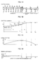
- FIG. 2 shows how global coordinate axes are set for a single crank throw
- FIG. 3 shows a decomposition of force acting on the crank throw on the local coordinate system.
- the fore state quantity B is calculated by solving the formula.
- the state quantity B is equivalent to a displacement vector q and a force vector Q which will be discussed later.
- the field transfer matrix equation and the point transfer matrix equation are repeatedly applied with the state quantity serving as an initial value in order to calculate state quantities over the entire crankshaft.
- d x , d y , and d z denote a displacement, distortion, or the like
- ⁇ x , ⁇ y , and ⁇ z denote the angle of twist, the angle of deflection, or the like.
- T x , M y , and M z denote twisting moment, bending moment, or the like
- F x , F y , and F z denote axial force, shearing force, or the like.
- displacement vector q' and force vector Q' which are state quantities of the local coordinate system, are represented by Formulas (3) and (4) given below.
- d x , d t , and d r denote a displacement, distortion, or the like
- ⁇ x , ⁇ t , and ⁇ r denote the angle of twist, the angle of deflection, or the like.
- T x' , M t , and M r denote twisting moment, bending moment, or the like
- F x' , F t , and F r denote axial force, shearing force, or the like.
- the point transfer matrix equation for calculating a state quantity from the fore (indicated by a subscript "F") to the aft (indicated by a subscript "A”) is represented by Formula (5) given below,
- i denotes a bearing number (the number of a shaft section divided by the bearings).
- Formula (8) given above is also used for coordinate conversion from a crank arm to a journal.
- Bearing height data is substituted into d z0 of h 2 (as will be described later, when only a vertical displacement is calculated, d y0 is to be set to "0 (zero)").
- a distance D d between adjacent crank throws may be represented by Formula (11) given below (where the subscript 1 with respect to d denoting a displacement, a deflection, or the like indicates a position (b) shown in FIG. 4 described later; and similarly, the subscript 2 indicates a position (h) shown in FIG. 4 )
- crankshaft deflection (Def) is represented by Formula (12) given below.
- Formula (11) given above may be transformed into Formula (13) given below.
- Formulas (14) and (15) Consequently, a crank deflection can be calculated by Formulas (14) and (15) given below.
- Formula (14) represents the vertical.direction while Formula (15) represents the horizontal direction.
- crank deflection is primarily dependent on the amount of deformation in a crankshaft center direction.
- Step A The field transfer matrix equation represented by Formula (5) is used for a bearing at portion (a).
- Step B At a bent portion (b), the left side of Formula (5) in Step A is substituted into the right side of the coordinate conversion formula represented by Formula (6), and the left side of Formula (6) at this point is substituted into the right side (journal) of the coordinate conversion formula represented by Formula (8).
- Step C At portion (c), the left side of Formula (8) in Step B is substituted into the right side of Formula (5)
- Step D At portion (d), the left side of Formula (5) in Step C is substituted into the right side of the coordinate conversion formula represented by Formula (9).
- Step E At portion (e), the left side of Formula (9) in Step D is substituted into the right side of Formula (5).
- Step F At portion (f), the left side of Formula (5) in Step E is used as the left side of Formula (9).
- Step G At portion (g), the right side [q'Q'1] T arm of Formula (9) in Step F is substituted into Formula (5).
- Step H At portion (h), the left side of Formula (5) in Step G is used as the left side of Formula (8), and the right side [q'Q'1]T journal of Formula (8) at this point is substituted into the right side of the coordinate conversion formula represented by Formula (7).
- Step I At portion (i), the left side of Formula (7) in Step H is substituted into the right side of Formula (5) .
- transfer from a crank throw to an adjacent crank throw is performed by using the point transfer matrix formula represented by Formula (10) and substituting the left side of Formula (5) in step I into the right side of Formula (10).
- Q also varies depending on f 1 , f 2 , h 1 , and h 2 of Formula (5) and Formula (10).
- the propeller shaft is assumed to be a reference line for the inclination ⁇ e and ⁇ i (however, the reference line need not be limited to the propeller shaft).
- the inclination ⁇ i of the intermediate shaft is represented by Formula (16) given below.
- the bearing height of the engine portion is represented by Formula (18) given below (provided that the aft-end bearing of the engine is used as a reference).
- the vertical displacement of a bearing due to thermal expansion of the engine may be derived as below.
- thermal expansion causes intermediate to high-level bending at the engine portion, which is represented by Formula (22) given below.
- a hull sag is calculated by Formula (25) given below.
- a bearing height (shafting alignment) which integrates the matters described above may be represented as follows.
- the engine portion is represented by Formula (28) given below (calculated by Formula (20), Formula (22), and Formula (26)).
- z j corresponds to d z0 in Formula (10).
- Formula (27) given above is used for the intermediate shaft bearing and the aft-tube bearing while Formula (28) is used for the engine bearings.
- Formula (28) represents a displacement using a line connecting the #1 bearing 5A and the #9 (n-3) bearing 5A (engine center line) as a height reference line, the heights d z0 of the #1 bearing 5A and the #9 (n-3) bearing 5A are both zero "0".
- a bearing height at the intermediate shaft and a bearing height at the engine are calculated based on a sag formula corresponding to an engine condition such as a hot state, a cold state, or the like and a load state of the ship or the like, and the bearing heights are substituted as initial heights into h 2 of Formula (10). Then, the transfer matrix method is used to calculate a state quantity, i.e., a displacement and an acting force, at each portion.
- crank deflection and a bearing load are calculated, and an assessment is made on whether or not the crank deflection and the bearing load fall in a preset evaluation range (more precisely, an assessment is made as to which evaluation level the crank deflection and the bearing load fall on).
- the bearing position within the horizontal plane on the crankshaft may be calculated by Formula (31) given below (the formula uses the aft-end bearing of the engine as a reference).
- y j corresponds to d y0 in h 2 of Formula (10).
- a state quantity (displacement and acting force) at each portion in the shafting is calculated using the transfer matrix method, the crank deflection of the engine is calculated based on the displacements, and an assessment is made on whether or not the deflection value falls in a preset evaluation range (more precisely, on which evaluation level the deflection value falls).
- a crank deflection (Def) may be calculated by Formula (14) and Formula (15) described above.
- a bearing load (F z ) may be calculated by Formula (32) given below when d z0 denotes the initial height of a targeted bearing (in this case, assumed to be the height of the center position of the shaft that is in contact with the bottommost face of the bearing) or, in other words, an initial bearing height, (d z ) denotes a calculated bearing height, and k z denotes the translational spring constant of the engine main body.
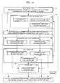
- step 1 specification data such as dimensions, loads, or the like of the crankshaft and the propulsion shafting, as well as an initial bearing height, are inputted.
- step 2 a state quantity or, in other words, a displacement (bearing height), and an acting force are calculated using the transfer matrix method.
- step 3 a judgment is made on whether a displacement d z in a height direction calculated in step 2 is oriented downward or not, and when oriented upward, a judgment is made on whether the shaft is in contact with a topmost face within the bearing or not.
- the procedure proceeds to step 4 in order to improve calculation accuracy, whereby the spring constant (k 2 ) is set to zero and the procedure returns to step 2 once again to perform calculation.
- step 5 when the difference between the bearing height calculated in step 2 and the initial bearing height (d z - d z0 ) either exceeds the acceptable value c between the crankshaft and the bearing metal or takes a negative value, the procedure proceeds to step 5.
- step 5 a crank defection and a bearing load are calculated based on Formula (14) and Formula (15) using the bearing height at each portion.
- step 6 a judgment is made on which evaluation level the crank deflection and the bearing load fall on. Subsequently, in step 7, an evaluation map is created and outputted.
- the calculation is to be continued with "zero" as the bearing load in the case where the difference between the bearing height and the initial bearing height falls within the range of the acceptable value c between the crankshaft and a bearing metal.
- a case where the difference between the bearing height and the initial bearing height exceeds the acceptable value or, in other words, where the bearing load takes a negative value corresponds to a range in which the uplift of the shaft occurs and therefore falls outside the allowable range.
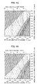
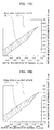
- FIG. 8 Shown in FIG. 8 is a map representation of evaluation levels of a crank deflection calculated based on the respective formulas described above when a hull sag is varied in 1 mm increments in an engine cold state and an engine hot state for a vertical installation condition (the inclination of the crankshaft and the inclination of the intermediate shaft) of the engine with respect to the evaluation condition, i.e., evaluation range of crank deflection.
- FIG. 8(a) represents a case of 0 mm hull sag in an engine cold state
- FIGS. 8(b) to 8(h) represent cases of 0 mm to 6 mm hull sag (in 1 mm increments) in an engine hot state.
- portion (0) represents an evaluation level "0" (within allowable range), portion (1) an evaluation level “1” (outside allowable range), portion (2) an evaluation level “2” (outside allowable range), and portion (3) an evaluation level “3” (outside allowable range).
- These evaluation levels correspond to a case in which there are three numerical values provided by an engine manufacturer or, more specifically, to a case in which, with these numerical values as boundaries, a level equal to or higher than an allowable value is designated level "3", a level equal to or smaller than the allowable value is designated level "2”, a level equal to or smaller than the allowable value in which readjustment is desirable is designated level "1", and a desirable level smaller than the readjustment (a normal level) is designated level "0".
- a user may select any acceptable level from the three described above.
- the evaluation level "0" is handled as an allowable range and the outside of the allowable range is divided into three evaluation levels "1" to "3"
- this three-way division of levels is used only to grasp a degree of divergence of crank deflection from the allowable range.
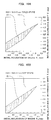
- FIG. 10 is a map representation of evaluation levels of bearing loads calculated based on the respective formulas described above when hull sag is varied in 1 mm increments in an engine cold state and an engine hot state for an installation condition of the engine (the inclination of the crankshaft (engine) and the inclination of the intermediate shaft) in which bearing loads do not take a negative value.
- FIG. 10(a) represents a case of 0 mm hull sag in an engine cold state
- FIGS. 10(b) to 10(h) represent cases of 0 mm to 6 mm hull sag in an engine hot state.
- portion (0) represents an evaluation level "0" (within allowable range) and portion (1) an evaluation level "1" (out of allowable range).
- portion (0) represents an evaluation level "0" (within allowable range) and portion (1) an evaluation level "1" (out of allowable range).
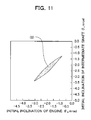
- a representation of an allowable range satisfying all of the conditions described above (a range of comprehensive evaluation) results in portion (0) shown in FIG. 11 .
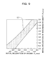
- an evaluation map representing an installation condition in which both a crank deflection and a bearing load fall in an allowable range assumes a range satisfying both portions (0), i.e., evaluation levels "0" of FIG. 9 and FIG. 11 (a comprehensive evaluation and which takes AND operations of binarized data with respect to the evaluation level "0").
- FIG. 13 is a map representation of evaluation values of crank deflection calculated based on the respective formulas described above when hull sag is varied in 1 mm increments in an engine cold state and an engine hot state for a horizontal installation condition (the inclination of the crankshaft (engine) and the inclination of the intermediate shaft) of the engine with respect to an evaluation condition, i.e., evaluation levels of crank deflection.
- portion (0) represents an evaluation level "0" (within allowable range), portion (1) an evaluation level "1" (out of allowable range), portion (2) an evaluation level "2" (out of allowable range), and portion (3) an evaluation level "3" (out of allowable range).
- evaluation levels are divided into similar stages as described with reference to FIG. 8 .
- installation should be performed so as to fall within the range represented by the portion (0) (evaluation level "0") shown in FIG. 13 .
- an alignment condition consistent with the horizontal crank deflection is calculated in advance as an adjustment amount using an inverse analysis (according to the technique described in Patent Document 1), and based on results thereof, a bearing metal is used which has a core whose inclination equals the average value of the inclination of the crankshaft (engine) and the inclination of the intermediate shaft.
- a crank deflection in a case of varying the core of an aft bearing inside the engine is calculated using a forward analysis method in order to verify the validity of the bearing before preparing the actual bearing.
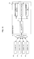
- a shafting alignment evaluating device of this ship primarily includes: a data input unit 31; a bearing position calculating unit 32; a shafting displacement calculating unit 33; an evaluation index calculating unit 34; an evaluating unit 35; and an output unit 36.
- various calculations by the evaluating device are to be executed by a program.
- a computer system is used.
- a terminal (computer terminal) is used as the data input unit 31 while the bearing position calculating unit 32, the shafting displacement calculating unit 33, the evaluation index calculating unit 34, and the evaluating unit 35 are provided on the side of a server (processing device (a computer is used)) connected to the terminal.
- a part of the output unit 36 is provided on the terminal side (obviously, the configuration may consist of a single computer).
- a computer terminal made up of, for example, a display screen, an arithmetic processing unit, a keyboard, and the like is used as the data input unit 31.
- the computer terminal is arranged so as to enable input, via the keyboard or the like, of specification data of the drive shafting, evaluation conditions (for example, a normal allowable value (minimum required), a value that preferably should be readjusted, and a maximum boundary value for a crank deflection, and a maximum allowable value and a minimum allowable value for a bearing load), the inclination of the engine or, i.e., an inclination ⁇ e of the crankshaft 2 (specifically, the inclination of a line connecting the fore-end bearing and the aft-end bearing of the engine), and an inclination ⁇ i of the intermediate shaft 3 disposed between the aft-tube bearing 5A and the intermediate bearing 5B of the engine.
- evaluation conditions for example, a normal allowable value (minimum required),
- the inclination ⁇ e of the crankshaft 2 and the inclination ⁇ i of the intermediate shaft 3 are arranged so as to be respectively inputted as single numerical values or as numerical ranges.
- Other data to be selected include the make of the engine.
- an evaluation condition can also be inputted through selection.
- An appropriate calculation model becomes usable by selecting a make.
- the aforementioned specification data include the specification data of the engine and the specification data of the intermediate shaft and the aft-tube.
- specification data may include dimensions of various members, distances between members, various coefficients, various moments which act on the respective shaft portions, as well as heights of bearings provided on shaft ends, amounts of deformation due to thermal expansion of the engine, and a sag of the double bottom portion of the engine room.
- the specification data of the engine may alternatively be arranged so as to be selected, after data from the engine manufacturer is received, from data registered beforehand in a storage unit regarding one or more engines. Obviously, specification data not registered can be inputted.
- a single numerical value is inputted as inclination data in a case where an evaluation of a combination ( ⁇ e , ⁇ i ) of the inclination of a pair of a crankshaft and an intermediate shaft is desired, or more specifically, when evaluating the current status of a ship in service.
- a numerical range is inputted in the case of newly-built ship in order to obtain information on a combination of appropriate inclination ( ⁇ e , ⁇ i ) which ensures that the engine itself is appropriately installed, and in the case of a ship in service, since the engine cannot be moved, a numerical range is inputted using the appropriate combination as a reference for the purpose of determining how far the opening position of a ring-like bearing metal, to be used fitted between a bearing and a shaft supported by the bearing, should be displaced from the center.
- the bearing position calculating unit 32 calculates a bearing position (initial bearing height, horizontal position) necessary for calculations by the shafting displacement calculating unit 33, and includes: a combination generating unit 41 for generating combination data when inclination ( ⁇ e , ⁇ i ) is inputted in the form of a numerical range; a height calculating unit 42 for calculating a bearing height with respect to a height reference line; and a horizontal position calculating unit 43 for calculating a bearing horizontal position with respect to a horizontal-direction reference line.
- the height calculating unit 42 calculates an initial bearing height in the vertical direction based on Formula (27) or Formula (28) provided above, while the horizontal position calculating unit 43 calculates an initial bearing horizontal position based on Formula (31) provided above.
- the initial bearing position calculated here is to be used in the calculation using the transfer matrix method. That is, in the vertical direction, the relationship between height and inclination with respect to an aft-tube center line can been seen from Formula (16) and Formula (17). In the horizontal direction, the relationship between height and inclination in the horizontal direction with respect to the aft-tube center line can been seen from Formula (29) and Formula (30).
- a predetermined increment e.g. 1 mm
- maximum sag e.g. 6 mm
- initial bearing positions are to be calculated for the number of variations obtained as the total number of combinations x "7" variations (data combining one inclination and one hull sag shall be referred to as a pattern).
- Evaluations may be performed (evaluation levels may be calculated) on all patterns by calculating initial bearing positions for all patterns, handing over the initial bearing positions to the evaluation index calculating unit 34 to respectively calculate evaluation indexes, and then handing over all the evaluation indexes to the evaluating unit 35.
- evaluations may be performed by generating one pattern at a time by the bearing position calculating unit 32 and performing an evaluation on the pattern according to the procedure described above and, subsequently, returning to the bearing position calculating unit 32 once again to generate and evaluate the next pattern.
- processing procedures are not limited to those just described and many variations exist, any processing procedure may be adopted. However, in the present first embodiment, it is assumed that processing is performed according to the procedure in which patterns are generated one by one.
- the shafting displacement calculating unit 33 calculates displacements at predetermined positions on the crankshaft 2 and the intermediate shaft 3 using initial bearing positions provided by the bearing position calculating unit 32.
- the predetermined positions are referred to as a part (portion) corresponding to each intersection of the crank arm and the journal and the position of each bearing (center position) necessary for calculating a crank deflection, and on the part and position, a displacement is to be calculated.
- the evaluation index calculating unit 34 calculates an evaluation index using the displacement of a predetermined position calculated by the shafting displacement calculating unit 33. While evaluation indexes include a crank deflection and a bearing load, either one or both of them may be used. While an operator specifies which of the evaluation indexes is to be used, since it is desirable to evaluate both indexes, the present first embodiment will be described on the premise that both indexes are to be evaluated.
- the evaluation index calculating unit 34 is provided with a crank deflection calculating unit 45 that calculates a crank deflection based on displacements (amounts of displacement) of parts corresponding to the aforementioned intersections and a bearing load calculating unit 46 that calculates a load on each bearing.
- a crank deflection is calculated by the crank deflection calculating unit 45 using fore and aft displacements of the same crank throw among the intersections.
- a bearing load is calculated by the bearing load calculating unit 46 using a vertical displacement among the displacements of an initial bearing position.
- the evaluating unit 35 compares an evaluation condition, i.e., an evaluation level stored in advance in the storage unit and, for example, recommended by the engine manufacturer with an evaluation index obtained through calculation, and determines which evaluation level the inclination combinations ( ⁇ e , ⁇ i ), ( ⁇ e' , ⁇ i' ) belong to.
- an evaluation condition i.e., an evaluation level stored in advance in the storage unit and, for example, recommended by the engine manufacturer with an evaluation index obtained through calculation
- ⁇ e , ⁇ i ) the maximum allowable value and the minimum allowable value of bearing loads at the engine, and limit values (the maximum limit value, a value desirably readjusted, a normal limit value) of a crank deflection in a cold state of the engine are shown.
- the maximum limit value a value desirably readjusted, a normal limit value
- bearing loads are classified into an evaluation level "0" between the minimum allowable value and the maximum allowable value, and a binarized evaluation level “1” of other levels requiring readjustment.
- four levels are set for crank deflections, namely, "0" for normal allowable values.
- "1” for values that are preferably readjusted
- "2” for values over the values that are preferably readjusted and up to the maximum limit value
- "3" for values exceeding the maximum limit value.
- an evaluation is performed on inclination combinations ( ⁇ e , ⁇ i ), ( ⁇ e' , ⁇ i' ) under each condition of a cold state or hot state of the engine and a sag range (upon engine installation, during ballasting, at full cargo), a logical AND operation of all evaluations of the same inclination combination is performed, and inclination combinations ( ⁇ e , ⁇ i ), ( ⁇ e' , ⁇ i' ) indicating the best evaluation level among all conditions are calculated.
- a crank deflection evaluating unit 51 performs the level placement described above when a crank deflection is inputted, and a bearing load evaluating unit 52 performs the level placement when a bearing load is inputted.
- processing is once again returned to the bearing position calculating unit 32.
- a comprehensive evaluation on the evaluation indexes is performed by a comprehensive evaluation unit 53.
- the comprehensive evaluation unit 53 carries out a comprehensive evaluation by performing a logical AND operation and binarization on each sag (in the present embodiment, seven patterns) of each inclination combination ( ⁇ e , ⁇ i ), ( ⁇ e' , ⁇ i' ) of all evaluation results respectively obtained by the crank deflection evaluating unit 51 and the bearing load evaluating unit 52.
- the output unit 36 generates a signal for screen output of an evaluation result and generates data to be printed out by a printer.
- the output unit 36 is also provided with an evaluation map creating unit 55.
- an evaluation is performed in the form of a numerical range on the inclination combinations ( ⁇ e , ⁇ i ), ( ⁇ e' , ⁇ i' ), the evaluation is outputted in the form of an evaluation map from the evaluation map creating unit 55.
- the evaluation map creating unit 55 reflects and graphically represents an evaluation result received from the evaluating unit 35 onto a two-dimensional plane having the two angles of inclination ( ⁇ e and ⁇ i ), ( ⁇ e' and ⁇ i' ) as two axes thereof. Output can be carried out per each pattern described above. Moreover, a consolidated evaluation and a comprehensive evaluation can also be outputted. When only one inclination combination ( ⁇ e , ⁇ i ), ( ⁇ e' , ⁇ i' ) is given, either only the evaluation result thereof, or both the evaluation result and the initial position of the bearing at that point (d z0 , d y0 ) can be outputted.
- each inclination combination ( ⁇ e , ⁇ i ), ( ⁇ e' , ⁇ i' ) is varied at a predetermined increment and in the same manner as described above, handed over to the respective calculating units 42 and 43 for all hull sags.
- the height calculating unit 42 and the horizontal position calculating unit 43 receive inclination combination data generated by the combination generating unit 41 and calculate an initial position (d z0 , d y0 ) of each bearing.
- the initial position (d z0 , d y0 ) of each bearing is handed over to the shafting displacement calculating unit 33, a calculation using the transfer matrix method is performed, and a portion corresponding to each intersection of the crank arm and the journal and a displacement (d x , d y , d z ) of each bearing are calculated.
- crank deflection from the evaluation index calculating unit 34 is compared with an evaluation condition, and a level placement result and a pattern at that point are associated with each other and stored in a storage unit (not shown). A comparison with an evaluation condition is also performed for a bearing load, and a level placement result and a pattern at that point are associated with each other and similarly stored.
- the comprehensive evaluation unit 53 first performs comprehensive evaluations (logical AND operations) respectively on a crank deflection and a bearing load for each evaluation index based on the evaluation results of the respective inclination combinations ( ⁇ e , ⁇ i ), ( ⁇ e' , ⁇ i' ), and then performs a comprehensive evaluation of both evaluation indexes or, in other words, a consolidated evaluation (specifically, a logical AND operation is performed on the comprehensive evaluations of the crank deflection and the bearing load for each inclination combination ( ⁇ e , ⁇ i ), ( ⁇ e' , ⁇ i' )).
- the output unit 36 retrieves prescribed evaluation results from the storage unit and creates an evaluation map at the evaluation map creating unit 55. Then, as required, the evaluation map is outputted to a display unit such as a screen or to a printing unit such as a printer. For example, output from the printer takes the form of an evaluation map that uses the inclination ( ⁇ e , ⁇ i ) as two-dimensional coordinate axes.
- an evaluation map which takes the inclination ⁇ e of the crankshaft and the inclination ⁇ i of the intermediate shaft in the vertical direction as coordinate axes and which represents the allowable ranges of crank deflection and bearing load and an evaluation map which takes the inclination ⁇ e' of the crankshaft and the inclination ⁇ i' of the intermediate shaft in the horizontal direction as coordinate axes and which represents the allowable ranges of crank deflection and bearing load are outputted.
- an operator can discover the allowable ranges of crankshaft inclination ⁇ e , ⁇ e' and intermediate shaft inclination ⁇ i , ⁇ i' in the vertical and horizontal directions.
- combination data for the same inclination as the previous hull sag is to be handed over to the respective calculating units 42 and 43.
- an inclination combination ( ⁇ e , ⁇ i ) in the vertical direction is varied at a predetermined increment, and in the same manner as described above, handed over to the respective calculating units 42 and 43 for all hull sags.
- the bearing height calculating unit 42 receives a pattern generated by the combination generating unit 41 and calculates an initial position (d z0 ) of the bearing.
- crank deflection calculated by the evaluation index calculating unit 34 is compared with an evaluation condition, and a level placement result and a pattern at that point are associated with each other and stored in a storage unit not shown.
- a comparison with an evaluation condition is also performed for the bearing load, and a level placement result and a pattern at that point are associated with each other and similarly stored.
- the comprehensive evaluation unit 53 respectively performs comprehensive evaluations (logical AND operations) on the crank deflection and the bearing load for each evaluation index based on evaluation results of each inclination combination ( ⁇ e , ⁇ i ) in the vertical direction, and then performs a comprehensive evaluation of both evaluation indexes or, in other words, a consolidated evaluation.
- the results of these consolidated evaluations are also stored in the storage unit. Subsequently, the processing proceeds to (3') described below. (3') At the combination generating unit 41, combination data for which the inclination combination ( ⁇ e' , ⁇ i' ) in the horizontal direction takes a minimum value is generated and handed over to the horizontal position calculating unit 43.
- the inclination combination ( ⁇ e' , ⁇ i' ) in the horizontal direction is varied in predetermined increments.
- the height calculating unit 42 retrieves an inclination combination ( ⁇ e , ⁇ i ) in the vertical direction whose comprehensive evaluation stored in the storage unit is within allowable range, and calculates an initial position d z0 of the bearing. However, this processing is performed only initially.
- the horizontal position calculating unit 43 receive a horizontal inclination combination ( ⁇ e' , ⁇ i' ) generated by the combination generating unit 41 and calculates an initial position d y0 of the bearing.
- (5') is the same as (5) in A.
- crank deflection calculating unit 45 of the evaluation index calculating unit 34 a horizontal crank deflection is calculated using the displacement of a portion corresponding to each intersection of the crank arm and the journal calculated in (5').
- the crank deflection from the evaluation index calculating unit 34 is compared with an evaluation condition, a level placement result and the inclination combination ( ⁇ e' , ⁇ i' ) in the horizontal direction are associated with each other and stored in the storage unit, and processing subsequently returns to (3').
- the state of the shafting alignment of the ship can be readily evaluated by measuring the inclination of the crankshaft (engine) and the inclination of the intermediate shaft.
- a device for evaluating the shafting alignment of a ship according to a second embodiment of the present invention will now be described.
- a client/server system is used in which a portion of functions of a data input unit and an output unit is provided at a client that is a terminal and other portions thereof are provided at a server device connected to the client via a network.
- a method is widely used in which information transmitted over the Internet (World Wide Web) is inputted using a client-side browsing software (browser) and transmitted to the server device, and output from the server device is displayed at the client side.
- client-side browsing software browser
- the present second embodiment is described in a mode in which the system is used by a client via generally available software, a description, of the client shall be omitted.
- the client is at least provided with a part of functions of a data input unit 31 and an output unit 36 (e.g., a screen display function, a printing function and the like).
- a server device 60 is provided with: a Web server (also referred to as an application unit) 63 to become an interface which is directly connected to the Internet 61 and exchanges data between a plurality of clients 62 and the server device 60; a user authenticating server (user authenticating unit) 64 for judging whether a client is a subscriber or not; a calculating server (calculating unit) 65 which performs calculations using data inputted from the client 62; and a usage management database 66 for storing a service used by a user. While the respective servers will be described as being disposed distributed across a plurality of computers connected via an intranet, it is obvious that the servers may also be disposed at a single server in which respective processing units are integrated.
- the Web server 63 plays a leading role in generating data for display forms and input forms to be displayed on the browser of the client 62.
- the Web server 63 hands over the data to the user authenticating server 64.
- the user authenticating server 64 conveys the authentication results to the Web server 63.
- processing is performed in which the Web server 63 hands over the data to the calculating server 65 and the calculating server 65 returns calculation results to the Web server 63.
- the Web server 63 is also capable of outputting information regarding the usage fee of the user to the client 62.
- the calculating server 65 is provided with all other components described in the first embodiment (a bearing position calculating unit, a shafting displacement calculating unit, an evaluation index calculating unit, an evaluating unit, the remainder of the output unit), and processing procedures are the same as in the first embodiment. Thus, a description of the calculation processing by the calculating server 65 shall be omitted.
- Menu 1 Creation of alignment evaluation map (M1-1)
- the application unit inquires of the calculating server 65 to verify a registered engine and already registered data, and transmits screen form data that enables selection of the make of the engine to the client 62.
- Ml-2 When the client 62 selects an unregistered engine, the Web server 63 transmits to the client 62 input form data displaying all input fields for necessary specification data, adjustable ranges of intermediate shaft inclination ⁇ i , ⁇ i' , and adjustable ranges of crankshaft inclination ⁇ e , ⁇ e' .
- Input form data is also transmitted to the client 62 when the registered engine is selected. However, in this case, an inquiry is made to the calculating server 65 and an input form that eliminates the need for input fields regarding pre-registered data is created.
- the input form is arranged to be alterable as required.
- the application unit hands over the data to the calculating server 65.
- the data is inputted to the data input unit 31 which outputs the map data of the respective comprehensive evaluations of a bearing load and a crank deflection as well as the consolidated evaluation of both comprehensive evaluation values.
- the application unit Upon receiving the map data, the application unit transmits evaluation map display form data to the client 62 and, at the same time, registers authenticated user information, time and date information, and usage-performance of the present menu to the usage management database 66.
- Menu 2 Alignment evaluation (bearing load) (M2-1) Omitted since same as Ml-1.
- M2-2 Omitted since same as M1-2.
- input fields, for which ranges cannot be specified, are provided for the inclination ( ⁇ e , ⁇ i ), ( ⁇ e' , ⁇ i' ).
- M2-3) Omitted since same as Ml-3.
- the application unit Upon receiving the output data, the application unit transmits to the client 62 display form data for displaying inclination ( ⁇ e , ⁇ i ), ( ⁇ e' , ⁇ i' ) and the result of good/bad judgment and, at the same time, registers authenticated user information, time and date information, and usage-performance of the present menu to the usage management database 66.
- Menu 3 Alignment evaluation (crank deflection) (M3-1) Omitted since same as M2-1. (M3-2) Omitted since same as M2-2. (M3-3) Omitted since same as M1-3. However, only crank deflection calculation is performed by the evaluation index calculating unit 34, only crank deflection evaluation is performed by the evaluating unit 35, and output includes only inputted inclination ( ⁇ e , ⁇ i ), ⁇ e' , ⁇ i' ) and a result of good/bad judgment. (M3-4) Omitted since same as M2-4.
- Menu 4 Alignment evaluation (consolidation of bearing load and crank deflection) (M4-1) Omitted since same as M2-1. (M4-2) Omitted since same as M2-2.
- an evaluation may alternatively be performed based only on a crank deflection or only on a bearing load.
- an evaluating method taking only a crank deflection into consideration is a method of evaluating the alignment of the drive shafting of a ship including a crankshaft of an engine, an intermediate shaft, and a propeller shaft, the method including: calculating a displacement at a predetermined portion of the drive shafting using a transfer matrix method, based on the inclination of the crankshaft and the inclination of the intermediate shaft; calculating the crank deflection of the crankshaft based on the displacement; and evaluating the alignment of the drive shafting by comparing the calculated crank deflection with a preset evaluation condition
- an evaluating device thereof includes: a data input unit for inputting specification data of drive shafting and data regarding an evaluation condition and the inclination of a crankshaft of an engine and the inclination of an intermediate shaft; a bearing position calculating unit for calculating respective bearing positions in the drive shafting using the specification data; a shafting displacement calculating unit for calculating a displacement at a predetermined portion of the drive shafting using a transfer matrix method
- an evaluating method taking only a bearing load into consideration is a method of evaluating the alignment of the drive shafting of a ship including a crankshaft of an engine, an intermediate shaft, and a propeller shaft, the method including: calculating a displacement at a predetermined portion of the drive shafting using a transfer matrix method, based on the inclination of the crankshaft and the inclination of the intermediate shaft; calculating a bearing load acting on each bearing based on the displacement; and evaluating the alignment of the drive shafting by comparing the calculated bearing load with a preset evaluation condition
- an evaluating device thereof includes: a data input unit for inputting specification data of drive shafting and data regarding an evaluation condition and the inclination of a crankshaft of an engine and the inclination of an intermediate shaft; a bearing position calculating unit for calculating respective bearing positions in the drive shafting using the specification data; a shafting displacement calculating unit for calculating a displacement at a predetermined portion of the crankshaft using the bearing positions calculated by the bearing position calculating unit
- the shafting alignment evaluating method is arranged so as to use an evaluation map indicating allowable ranges of a crank deflection and a bearing load calculated in advance in accordance with the inclination of a crankshaft and the inclination of an intermediate shaft, the inclination of the respective shafts which fall within the allowable ranges can be readily known when, for example, installing an engine and propeller shafting in a hull.
- operating instructions on shafting alignment can be issued with extreme ease.
- an evaluation of current shafting alignment can be readily performed.
Landscapes
- Engineering & Computer Science (AREA)
- Combustion & Propulsion (AREA)
- Ocean & Marine Engineering (AREA)
- Mechanical Engineering (AREA)
- Chemical & Material Sciences (AREA)
- Physics & Mathematics (AREA)
- General Physics & Mathematics (AREA)
- Theoretical Computer Science (AREA)
- General Engineering & Computer Science (AREA)
- Fluid Mechanics (AREA)
- Shafts, Cranks, Connecting Bars, And Related Bearings (AREA)
- Testing Of Devices, Machine Parts, Or Other Structures Thereof (AREA)
- Length Measuring Devices With Unspecified Measuring Means (AREA)
Applications Claiming Priority (1)
| Application Number | Priority Date | Filing Date | Title |
|---|---|---|---|
| PCT/JP2006/320734 WO2008047424A1 (fr) | 2006-10-18 | 2006-10-18 | Procédé et dispositif pour évaluer l'alignement d'arbre de transmission de navire |
Publications (2)
| Publication Number | Publication Date |
|---|---|
| EP2088074A1 true EP2088074A1 (de) | 2009-08-12 |
| EP2088074A4 EP2088074A4 (de) | 2014-05-21 |
Family
ID=39313683
Family Applications (1)
| Application Number | Title | Priority Date | Filing Date |
|---|---|---|---|
| EP06821928.6A Withdrawn EP2088074A4 (de) | 2006-10-18 | 2006-10-18 | Verfahren und vorrichtung zur bewertung der wellenausrichtung eines schiffs |
Country Status (6)
| Country | Link |
|---|---|
| US (2) | US20090271053A1 (de) |
| EP (1) | EP2088074A4 (de) |
| JP (1) | JP4999857B2 (de) |
| KR (1) | KR101213551B1 (de) |
| CN (1) | CN101516719B (de) |
| WO (1) | WO2008047424A1 (de) |
Cited By (1)
| Publication number | Priority date | Publication date | Assignee | Title |
|---|---|---|---|---|
| EP2481941A4 (de) * | 2009-09-24 | 2018-01-03 | JTEKT Corporation | Spindelvorrichtung für ein bearbeitungszentrum |
Families Citing this family (22)
| Publication number | Priority date | Publication date | Assignee | Title |
|---|---|---|---|---|
| GB0613941D0 (en) * | 2006-07-13 | 2006-08-23 | Pml Flightlink Ltd | Electronically controlled motors |
| JP4986734B2 (ja) * | 2007-06-25 | 2012-07-25 | 日立造船株式会社 | 軸受高さの修正量決定方法 |
| JP5171599B2 (ja) * | 2008-12-18 | 2013-03-27 | 日立造船株式会社 | 船舶における軸系アライメントの評価方法 |
| CN102032854B (zh) * | 2009-09-28 | 2012-08-08 | 上海联合滚动轴承有限公司 | 风电主轴承的测量装置 |
| CN102620705A (zh) * | 2012-04-01 | 2012-08-01 | 中联重科股份有限公司 | 回转机构的回转角度检测方法、装置、系统与工程机械 |
| CN103810305A (zh) * | 2012-11-07 | 2014-05-21 | 中国舰船研究设计中心 | 一种船舶推进轴系校中计算方法 |
| JP6178251B2 (ja) * | 2013-10-25 | 2017-08-09 | 株式会社神戸製鋼所 | ターボ機械の動特性演算方法およびターボ機械の動特性演算装置 |
| CN104976325B (zh) * | 2014-04-02 | 2018-01-26 | 华中科技大学 | 一种顺应挠度曲线的旋转轴系的轴承孔系布置方法 |
| US9804585B2 (en) * | 2014-07-29 | 2017-10-31 | Deere & Company | Computer program and method for evaluating a crankshaft |
| CN105021400B (zh) * | 2015-07-07 | 2018-03-16 | 武汉理工大学 | 用于船舶推进轴系试验台的带有液压加载装置的中间轴承 |
| CN106202666B (zh) * | 2016-07-01 | 2019-03-05 | 大连理工大学 | 一种船舶轴系轴承位移调整的计算方法 |
| CN108416159B (zh) * | 2018-03-22 | 2022-05-20 | 中国人民解放军海军工程大学 | 一种舰船轴系优化方法及其优化平台 |
| CN109764832A (zh) * | 2019-01-04 | 2019-05-17 | 广州文冲船厂有限责任公司 | 一种船舶推进轴系校中方法 |
| CN112339934B (zh) * | 2020-09-29 | 2023-12-08 | 沪东中华造船(集团)有限公司 | 一种船舶安装尾管密封装置的轴承式校中方法 |
| CN112697367A (zh) * | 2020-12-23 | 2021-04-23 | 武汉理工大学 | 一种船舶推进轴系纵横耦合振动实验台 |
| CN113562138B (zh) * | 2021-08-27 | 2022-11-25 | 芜湖造船厂有限公司 | 一种船舶斜长轴拉线方法 |
| CN114111569B (zh) * | 2021-10-29 | 2023-03-21 | 沪东中华造船(集团)有限公司 | 一种倾斜式轴系中间轴承位置修正方法 |
| CN114132452B (zh) * | 2021-12-23 | 2023-04-18 | 武昌船舶重工集团有限公司 | 一种用于船体轴承的同轴定位方法 |
| CN114701618B (zh) * | 2022-03-10 | 2023-05-16 | 江南造船(集团)有限责任公司 | 一种基于总段建造的船舶精度控制方法 |
| CN115711609B (zh) * | 2022-11-04 | 2024-06-11 | 沪东中华造船(集团)有限公司 | 一种艉管后轴承双斜率精度检验方法 |
| CN119845593B (zh) * | 2025-03-19 | 2025-08-15 | 中国航发沈阳发动机研究所 | 一种同侧输入的双轴压气机试验器转子同心度预留方法 |
| CN120735917B (zh) * | 2025-08-29 | 2025-11-18 | 中国船舶集团有限公司第七一九研究所 | 一种船舶短跨距非对称负载轴系安装调整方法 |
Family Cites Families (14)
| Publication number | Priority date | Publication date | Assignee | Title |
|---|---|---|---|---|
| US2229788A (en) * | 1939-03-14 | 1941-01-28 | Appleton Thomas Jay | Dual crankshaft engine |
| US2386097A (en) * | 1941-10-18 | 1945-10-02 | Briggs Mfg Co | Coupling |
| US3695637A (en) * | 1970-05-06 | 1972-10-03 | Satterthwaite James G | Inflatable coupling |
| US3685368A (en) * | 1971-02-09 | 1972-08-22 | Laval Turbine | Bearing system for minimizing shaft tilting |
| US3868833A (en) * | 1972-12-21 | 1975-03-04 | Brunswick Corp | Shaft coupling apparatus particularly for marine inboard-outboard propulsion systems |
| US4246780A (en) * | 1979-04-30 | 1981-01-27 | The United States Of America As Represented By The Secretary Of The Navy | Force sensing system |
| US4408994A (en) * | 1980-09-18 | 1983-10-11 | Outboard Marine Corporation | Transom mounted marine propulsion device with fore and aft crankshaft and power shaft |
| US4887983A (en) * | 1988-09-09 | 1989-12-19 | Brunswick Corporation | Chain drive marine propulsion system with dual counterrotating propellers |
| US5421753A (en) * | 1991-05-13 | 1995-06-06 | Roos; Paul W. | Marine jet drive |
| FR2689934B1 (fr) * | 1992-04-10 | 1994-06-17 | Siemens Automotive Sa | Procede et dispositif de detection des irregularites de combustion d'un moteur en particulier a moyen et haut regimes, application a un systeme de controle d'un moteur a injection. |
| US6029109A (en) * | 1996-04-15 | 2000-02-22 | Siemens Automotive S.A. | Method for calculating the torque of an internal combustion engine |
| JP2001039382A (ja) * | 1999-07-30 | 2001-02-13 | Hitachi Zosen Corp | 船舶機関の中間軸調心装置 |
| JP3868270B2 (ja) * | 2001-05-01 | 2007-01-17 | 日立造船株式会社 | 舶用推進装置における駆動軸系の位置検出方法および位置検出装置並びに位置検出用プログラム |
| EP2268209A4 (de) * | 2008-04-11 | 2014-11-12 | Physcient Inc | Verfahren und vorrichtungen zur verringerung von gewebetrauma bei operationen |
-
2006
- 2006-10-18 JP JP2008539640A patent/JP4999857B2/ja not_active Expired - Fee Related
- 2006-10-18 US US12/311,576 patent/US20090271053A1/en not_active Abandoned
- 2006-10-18 EP EP06821928.6A patent/EP2088074A4/de not_active Withdrawn
- 2006-10-18 KR KR1020097000377A patent/KR101213551B1/ko not_active Expired - Fee Related
- 2006-10-18 CN CN2006800556336A patent/CN101516719B/zh not_active Expired - Fee Related
- 2006-10-18 WO PCT/JP2006/320734 patent/WO2008047424A1/ja not_active Ceased
-
2012
- 2012-12-19 US US13/719,632 patent/US20130158781A1/en not_active Abandoned
Cited By (1)
| Publication number | Priority date | Publication date | Assignee | Title |
|---|---|---|---|---|
| EP2481941A4 (de) * | 2009-09-24 | 2018-01-03 | JTEKT Corporation | Spindelvorrichtung für ein bearbeitungszentrum |
Also Published As
| Publication number | Publication date |
|---|---|
| KR101213551B1 (ko) | 2012-12-18 |
| KR20090079872A (ko) | 2009-07-22 |
| JP4999857B2 (ja) | 2012-08-15 |
| JPWO2008047424A1 (ja) | 2010-02-18 |
| CN101516719B (zh) | 2012-05-23 |
| US20130158781A1 (en) | 2013-06-20 |
| CN101516719A (zh) | 2009-08-26 |
| EP2088074A4 (de) | 2014-05-21 |
| US20090271053A1 (en) | 2009-10-29 |
| WO2008047424A1 (fr) | 2008-04-24 |
Similar Documents
| Publication | Publication Date | Title |
|---|---|---|
| US20130158781A1 (en) | Method and device for evaluating shafting alignment of ship | |
| Ehlers et al. | Numerical and experimental investigation on the collision resistance of the X-core structure | |
| Robertson et al. | Offshore code comparison collaboration, continuation: Phase II results of a floating semisubmersible wind system | |
| JP5073092B2 (ja) | 船舶における軸系アライメントの評価方法および評価装置 | |
| Ku et al. | Dynamic response simulation of an offshore wind turbine suspended by a floating crane | |
| Yeter et al. | Fragility analysis of an ageing monopile offshore wind turbine subjected to simultaneous wind and seismic load | |
| EP1310763B1 (de) | Verfahren und Vorrichtung zum Detektieren der Einstellposition einer Kurbelwelle, und Programm zur Detektion der Einstellposition. | |
| Ferreira et al. | A reduced-order model to predict the natural frequencies of offshore wind turbines considering soil–structure interaction | |
| Ma et al. | Multi-body dynamic transfer matrix modeling and validation for full-scale wind turbine blades in biaxial fatigue testing systems | |
| Harold | Rotordynamic modeling and analysis procedures: a review | |
| Bottasso et al. | Estimation of blade structural properties from experimental data | |
| JP4986734B2 (ja) | 軸受高さの修正量決定方法 | |
| Cukor et al. | An inverse approach for load identification of cracked wind turbine components | |
| Chellapandi et al. | Progressive Deformation Modes of G91 Steel Subject to Stress–Strain Cycles: Viscoplastic Simulation Towards Developing High-Temperature Design Rules | |
| Nekstad et al. | Enhancing the Precision of Fatigue Analysis for Crucial Jacket Tubular Joints | |
| Solís et al. | Structural analysis of La Giralda's 16th-century sculpture/weather vane | |
| Ghoujehzadeh et al. | Design and performance evaluation of an optimised 7075 aluminium–scandium connecting Rod for the Peugeot XU7JP engine | |
| Murawski et al. | Optimization of marine propulsion system’s alignment for aged ships | |
| Lim et al. | Global Performance and Structural Digital Twins for a Floating Offshore Wind Turbine | |
| Oikonomou | Software Development for Dynamic Behavior Assessment of the Propulsion System with Parametric Design | |
| Dardamanis et al. | Hull deflection estimation model for marine shaft alignment applications | |
| Vassilopoulos | Longitudinal Stiffness Analyses for the Propulsion Shafting Systems of the Polar Class Icebreakers | |
| Shao et al. | Reliability-based design optimization of offshore wind turbine support structure considering pile-soil coupling effect | |
| Santini-Bell et al. | Nondestructive testing for design verification of Boston's Central Artery underpinning frames and connections | |
| Campos Lopez | Conceptual design of monopile to support. The IEA 22-Megawatt offshore reference wind turbine: assessment of conceptual design methodology |
Legal Events
| Date | Code | Title | Description |
|---|---|---|---|
| PUAI | Public reference made under article 153(3) epc to a published international application that has entered the european phase |
Free format text: ORIGINAL CODE: 0009012 |
|
| 17P | Request for examination filed |
Effective date: 20090414 |
|
| AK | Designated contracting states |
Kind code of ref document: A1 Designated state(s): AT BE BG CH CY CZ DE DK EE ES FI FR GB GR HU IE IS IT LI LT LU LV MC NL PL PT RO SE SI SK TR |
|
| DAX | Request for extension of the european patent (deleted) | ||
| A4 | Supplementary search report drawn up and despatched |
Effective date: 20140425 |
|
| RIC1 | Information provided on ipc code assigned before grant |
Ipc: B63H 23/34 20060101ALI20140417BHEP Ipc: B63B 9/00 20060101AFI20140417BHEP |
|
| GRAP | Despatch of communication of intention to grant a patent |
Free format text: ORIGINAL CODE: EPIDOSNIGR1 |
|
| RIC1 | Information provided on ipc code assigned before grant |
Ipc: B63H 23/34 20060101ALI20141030BHEP Ipc: B63B 9/00 20060101ALI20141030BHEP Ipc: G01M 17/00 20060101AFI20141030BHEP |
|
| INTG | Intention to grant announced |
Effective date: 20141112 |
|
| STAA | Information on the status of an ep patent application or granted ep patent |
Free format text: STATUS: THE APPLICATION IS DEEMED TO BE WITHDRAWN |
|
| 18D | Application deemed to be withdrawn |
Effective date: 20150324 |