EP2088089A1 - Bouchon en plastique doté d'un surbouchage incluant une clé et procédé - Google Patents
Bouchon en plastique doté d'un surbouchage incluant une clé et procédé Download PDFInfo
- Publication number
- EP2088089A1 EP2088089A1 EP09250253A EP09250253A EP2088089A1 EP 2088089 A1 EP2088089 A1 EP 2088089A1 EP 09250253 A EP09250253 A EP 09250253A EP 09250253 A EP09250253 A EP 09250253A EP 2088089 A1 EP2088089 A1 EP 2088089A1
- Authority
- EP
- European Patent Office
- Prior art keywords
- closure
- plug
- overcap
- projections
- container
- Prior art date
- Legal status (The legal status is an assumption and is not a legal conclusion. Google has not performed a legal analysis and makes no representation as to the accuracy of the status listed.)
- Withdrawn
Links
- 238000000034 method Methods 0.000 title claims description 9
- 239000004033 plastic Substances 0.000 title description 44
- 238000010276 construction Methods 0.000 description 14
- 238000009434 installation Methods 0.000 description 8
- 239000002184 metal Substances 0.000 description 5
- 239000002991 molded plastic Substances 0.000 description 5
- 230000006870 function Effects 0.000 description 4
- 239000000945 filler Substances 0.000 description 3
- 238000007493 shaping process Methods 0.000 description 3
- 238000002788 crimping Methods 0.000 description 2
- 238000012986 modification Methods 0.000 description 2
- 230000004048 modification Effects 0.000 description 2
- 230000002093 peripheral effect Effects 0.000 description 2
- 230000002441 reversible effect Effects 0.000 description 2
- 230000004075 alteration Effects 0.000 description 1
- 230000003466 anti-cipated effect Effects 0.000 description 1
- 150000001875 compounds Chemical class 0.000 description 1
- 230000008030 elimination Effects 0.000 description 1
- 238000003379 elimination reaction Methods 0.000 description 1
- 238000003780 insertion Methods 0.000 description 1
- 230000037431 insertion Effects 0.000 description 1
- 230000007246 mechanism Effects 0.000 description 1
- 230000001737 promoting effect Effects 0.000 description 1
- 238000003466 welding Methods 0.000 description 1
Images




Classifications
-
- B—PERFORMING OPERATIONS; TRANSPORTING
- B65—CONVEYING; PACKING; STORING; HANDLING THIN OR FILAMENTARY MATERIAL
- B65D—CONTAINERS FOR STORAGE OR TRANSPORT OF ARTICLES OR MATERIALS, e.g. BAGS, BARRELS, BOTTLES, BOXES, CANS, CARTONS, CRATES, DRUMS, JARS, TANKS, HOPPERS, FORWARDING CONTAINERS; ACCESSORIES, CLOSURES, OR FITTINGS THEREFOR; PACKAGING ELEMENTS; PACKAGES
- B65D39/00—Closures arranged within necks or pouring openings or in discharge apertures, e.g. stoppers
- B65D39/08—Threaded or like closure members secured by rotation; Bushes therefor
- B65D39/082—Bung-rings and bungs for bung-holes
-
- B—PERFORMING OPERATIONS; TRANSPORTING
- B65—CONVEYING; PACKING; STORING; HANDLING THIN OR FILAMENTARY MATERIAL
- B65D—CONTAINERS FOR STORAGE OR TRANSPORT OF ARTICLES OR MATERIALS, e.g. BAGS, BARRELS, BOTTLES, BOXES, CANS, CARTONS, CRATES, DRUMS, JARS, TANKS, HOPPERS, FORWARDING CONTAINERS; ACCESSORIES, CLOSURES, OR FITTINGS THEREFOR; PACKAGING ELEMENTS; PACKAGES
- B65D2401/00—Tamper-indicating means
- B65D2401/15—Tearable part of the closure
Definitions
- the present invention relates in general to plastic plugs that are constructed and arranged to assemble into a container opening, typically by threading.
- the opening may be formed directly into the container or may be defined by a threaded flange.
- the present invention relates to the described style of plastic plug that receives an overcap.
- the overcap is constructed and arranged to assemble to the plastic plug and/or container with a tamper-evident configuration and function.
- the plastic plug is a unitary, molded component and the overcap is a unitary, molded plastic component. These two components are pre-assembled prior to plug insertion into the container opening without any overcap connection to the container.
- the tamper-evident component is a plastic cover that includes a skirt that cooperates with ratchet projections on an outer surface of the container opening.
- the size and shape complexity of this tamper-evident component adds to the component cost.
- the plastic plug threads into the neck opening of the container and then the tamper-evident component is engaged on the container.
- the tamper-evident component is of a part-metal construction in combination with a plastic overcap.
- a metal ring overlays the plastic skirt of the overcap such that crimping of the metal ring causes the plastic skirt to be crimped around a cooperating form on the outer surface of the container neck opening, after the plastic plug is threaded into the neck opening of the container.
- This tamper-evident component similar to the first-described prior art component, is a more costly component that requires a specific style of container due to the structural cooperation between the tamper-evident overcap and the container.
- the tamper-evident overcap described herein as one embodiment of the present invention provides a simpler design that engages only the plug, providing greater versatility since the container style does not have to be selected to cooperate with a particular style of tamper-evident overcap.
- the plastic plug construction that is part of the prior art and depicted in part as one portion of the present disclosure includes interior structural features or forms for facilitating the threading of the plug into and out of the container neck opening, the present invention does not use those features for the initial assembly of the plug and overcap combination into the container neck opening.
- the tamper-evident overcap is preassembled to the plastic plug and those plug features (interior) that might otherwise be used for tightening the plastic plug into the neck opening are covered by the tamper-evident overcap.
- the plug and overcap constructions disclosed herein require a different method of installation and different tooling, both of which are described herein and both of which constitute an aspect of this overall invention.
- the present disclosure provides a simple and reliable and aesthetically-pleasing, low cost tamper-evident overcap that assembles to the plastic plug.
- the overcap does not interface with the container neck opening, thereby allowing a wider range of container neck styles that remain compatible with the threaded plug. This wider range of container neck opening styles also remains compatible with the tamper-evident overcap as disclosed herein.
- Each outer peripheral portion of the plastic plugs disclosed herein includes unique structural forms that interfit with a unique installation tool for advancing the plug into the container opening. This unique installation tool can also be used for removing the plug from the container opening.
- the plug styles disclosed herein in combination with the unique installation tool comprises a container closure system.
- a closure for a container opening comprises a plug including installation tool-engaging forms and an overcap, the closure being constructed and arranged to be received within the container opening, the overcap being attached to the plug so as to create an integral assembly.
- One object of the present disclosure is to provide an improved closure for a container including a plastic plug and overcap.
- System 20 includes a container opening 21, square-cut gasket 22, a unitary, molded plastic plug 23 and a unitary, molded plastic tamper-evident cover 24.
- the assembly of component parts 22-24 into container opening 21 is illustrated in FIG. 5 .
- the cylindrical wall 27 that defines internally-threaded opening 21 includes at least one ratchet tab 28, two of which are illustrated in FIG. 3 .
- the tamper-evident cover 24 includes a lower skirt 29 connected to cover body 30.
- the inside surface 31 of skirt 29 includes a series of ratchet teeth 37 for engagement with tabs 28 so as to prevent removal.
- the center portion 33 of cover body 30 is constructed and arranged for access to the top interior portion of plug 23.
- the recessed interior portion of plug 23 includes a shelf and is integrally formed with four, equally-spaced, raised bosses 23a extending above the shelf. A recessed area 23b between each adjacent pair of bosses 23a results from this spaced-apart construction. Each boss 23a defines an interior opening 23c.
- This structural configuration on the interior portion of plug 23 enables plug 23 to be removed by the use of a cooperatively-styled wrench that is available from the plug manufacturer. When tamper-evident cover 24 is properly installed or assembled, the interior portion of plug 23 is accessible. This same construction is applicable to plug 43 as described hereinafter.
- System 20 represents one style of prior art closure and container design that is being improved upon by the embodiments of the present disclosure.
- System 40 includes a container opening 41, a gasket 42, a unitary, molded plastic plug 43 and tamper-evident cover 44.
- the assembly of component parts 42-44 into container opening 41 is illustrated in FIG. 10 .
- the annular wall 47 that defines internally-threaded opening 41 includes a generally cylindrical wall extension 48.
- the tamper-evident cover 44 rests on the upper edge 49 of wall extension 48 while lower skirt 50 wraps around annular form 51.
- Tamper-evident cover 44 includes a unitary, molded plastic body 52 and a surrounding metal shell 53.
- Each cylindrical wall 27 and 47 includes a raised annular rib 27a and 47a, respectively, that is embedded into its corresponding gasket 22 and 42, respectively.
- Gaskets 22 and 42 are substantially identical to each other in form, fit, and function.
- gaskets 22 and 42 are square-cut gaskets that fit between the radial flange of the plastic plug and the upper surface of the wall that defines the container neck opening.
- plastic plugs 23 and 43 these two components are substantially identical to each other in form, fit and function.
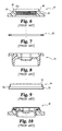
- Closure 59 includes a plastic plug 60 and a cooperating plastic overcap 61, the details of each being illustrated in FIGS. 11-16 .
- the unitary plastic plug 60 is similar to prior art plugs 23 and 43, except for the unique contouring or shaping of the peripheral portion 68 of the radial flange 69 of plastic plug 60.
- Radial flange 69 extends radially outwardly from the threaded body 70 and terminates in short, depending axial wall 71 that helps to define inverted gasket channel 72.
- the upper surface 73 of flange 69 is shaped or contoured with a uniform, equally-spaced series of curved, raised projections 76.
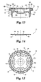
- Each rounded projection 76 has a generally part-hemispherical shape with a curved or rounded outer edge or surface form and appearance in a top plan view (see FIG. 15 ) and a curved or rounded upper edge or surface form and appearance in a front or side elevational view (see FIG. 11 ). Since the uppermost surface 76a of each projection 76 includes a small flat area, the overall projection 76 form is best described as "part-hemispherical".
- plug 60 includes twenty-five (25) projections 76 that are uniformly spaced and integrally connected or linked by recessed portions 77.
- This arrangement of projections has the shape of an annular ring. Although the preferred embodiment provides a full or complete ring, it is envisioned that gaps could be left. This results in arcs or sectors of projections 76.
- the concave edge 78 of each portion 77 is located at approximately the diameter of the curved or rounded outer or upper portion of each projection 76.
- the wrench forms 79 on the interior of the plug 60 are covered over and are not accessible to the installer until such time as the overcap 61 is defeated or removed. It therefore becomes necessary to provide some means, method, structure and/or tooling to be able to properly grip onto closure 59 in order to securely and tightly thread the closure (actually the plug portion of the closure) into the container opening 62.
- the projections 76 provide the means and structure for installing the closure 59 into the container opening 62.
- the tooling that is used for this installation is "socket" wrench 82 (see FIGS. 17A and 17B ).
- the head 83 of the socket is recessed and shaped with generally part-hemispherical recesses 85 in the form of small, rounded pockets that are equal in number and sized and arranged in terms of their spacing and overall geometry to fit securely over the entire series of projections 76 with a secure and reliable interfit, as would be expected from a properly sized and shaped socket wrench.
- the bottom or base 85a of each socket recess 85 includes a small flat area that generally matches its counterpart area of projection surface 76a.
- the socket recesses 85 can be a full annular ring, as the "extra" recesses merely fit into the gaps.
- the matching shape, number, and spacing of recesses 85 relative to projections 76 ensures that rotation of the socket, specifically rotation of the socket head, results in rotation of the plug 60 and thus rotation of the closure 59 as it is advanced into threaded engagement into the container opening.
- the properly aligned interfit of the recesses 85 securely on top of, over, and around the projections 76 means that, once properly aligned, there should be no slippage or disconnect in the form of the socket ramping off of the individual projections.
- the socket recesses 85 are not properly aligned onto the raised (part-hemispherical) projections 76, then it might be possible for the wrench 82 to slip off of or out of engagement.
- the part-hemispherical form of the projections 76 and the cooperating part-hemispherical form of the recesses 85 means that any such slippage or slide off will not damager either the plug 60 or the wrench 82.
- part-hemispherical is believed to be the most appropriate in order to describe the specific geometry.
- that term is not intended to be limiting, as virtually any type of rounded form would be suitable, so long as there is an adequate raised and recessed extent on the two cooperating forms sufficient to provide an interfit that would then enable the wrench to drive the plug without slippage.
- the geometry and shape of each recess 85 needs to match.
- the number of each form there needs to be a sufficient degree of interfit or engagement such that rotation of the socket transmits into rotation of the plug.
- wrench 82 is a specialized, unique, non-standard design whose availability and distribution is strictly controlled. Wrench 82 is made available only to authorized installers, as selected by the owner of this design, such as container or drum manufacturers and fillers. Unless wrench 82 is available, there is no other accessible structural portion or feature of closure 59 that can, from a practical standpoint, be used for installing the closure 59. If it becomes necessary at some point in the overall cycle of the drum to remove the closure without first defeating and/or removing the overcap 61, then wrench 82 would be required for that removal step, at least in a practical sense such that the closure 59 is not damaged.
- the overcap 61 of closure 59 is attached to the upper surface 73 of radial flange 69 so as to close off the interior portion and deny access to the wrench forms 79.
- the preferred method of attachment of overcap 61 to plug 60 is by ultrasonic spot welding.
- the spot weld locations can be on the recessed annular ring surface 86 or on the upper surface 87 of one or more of the wrench forms 79, or both, see FIG. 15 .
- annular rib 88 that generally coincides in height to the uppermost edge or surface of each projection.
- Surface 86 is axially below the uppermost edge or surface of each projection 76 and of rib 88 (see FIG. 13 ) by a distance the generally corresponds to the thickness of the overcap 61. This relationship is illustrated in FIG. 13 and helps explain why the overcap 61 is not otherwise visible in FIG. 11 .
- Overcap 61 is a relatively thin, unitary plastic member having an upper panel 92 and an interior, depending annular wall 93.
- the upper panel 92 defines a weakened score line 94 that creates a circular pull tab 95 that connects at portion 96 to annular ring 97.
- the weakened score line 94 extends around pull tab 95 and extends around annular ring 97.
- Annular ring 97 is a tear-out portion.
- overcap 61 The construction and arrangement of overcap 61, including its generally smooth and flat upper surface of panel 92 and its relative position on plug 60, allows overcap 61 to be used for indicia marking, customer logos, etc.
- the edge area marked as "M" in FIGS. 12 and 13 includes an approximate starting location or outer edge for such indicia marking, customer logos, etc.
- overcap 61 provides a practical location due to its visibility. When the overcap 61 is pulled free of plug 60, any such indicia marking, etc., would be removed. This provides for initial or first-use instructions without the markings or logos remaining a part of the closure once it is put into service.
- Overcap 123 has a similar construction and a similar capability in terms of indicia marking, etc., as described for overcap 61.
- the plug 60 includes an interior shelf 101 and the open space 102 above shelf 101 includes radially inwardly-projecting forms 79 and alternating recesses 104. Each form 79 defines a central opening 103. These interior shapes that are defined above shelf 101 are used for plug tightening and removal after initial opening. As described, the overcap 61 is securely attached to the plug 60 prior to initial assembly of the combination into the threaded container opening 62.
- wrench 82 as the specialized tooling for the installation of closure 59 into the container opening 62
- more conventional equipment or tooling can be used in cooperation with the plug 60 interior shapes or forms to permit removal of the plug from opening 62 and to permit reclosing of the opening 62 with plug 60.
- the threaded style for the threaded body 70 of plug 60 is preferably a buttress thread or pipe thread (as shown).
- the socket wrench 82 includes a wrench handle 108 for grasping and this wrench handle is constructed and arranged to connect to the open socket head 83 with a releasable square drive.
- the distal end 109 of socket wrench 82 includes a reversible, ratchet construction and a quick release for the square drive connection.
- the square opening 110 in head 83 is centered in head 83 and is constructed and arranged for receipt of the square drive post 111 of socket wrench 82.
- the first or preliminary step is to securely attach overcap 61 to plug 60 in order to create the integral assembly that is closure 59.
- the initial threading of closure 59 into the container opening 62, or at least the starting of that threading, begins by aligning the threaded body of plug 60 with opening 62. It is anticipated that the initial or lead in threading would be started by hand so as to prevent or at least reduce the risk of cross threading.
- the plug 60 will thread into opening 62 very easily and, once started, the manual rotation can be replaced by the use of wrench 82.
- the uniquely-styled wrench 82 is fitted down onto the plug 60 so that recesses 85 align with and receive the projections 76.
- This ball and socket-type of fit allows torque to be transferred from the socket head through projections 76 to plug 60.
- the turning of the plug advances the closure 59 into the opening 62 of the container.
- closure 120 is constructed and arranged in a manner that is generally equivalent to closure 59, except for the part-hemispherical, raised projections 76 that are replaced with gear teeth 121 as part of closure 120.
- the description herein of "gear" teeth is intended to suggest the general dentate profile shape of these forms rather than gear ratios or drive trains.
- Plug 122 is generally equivalent to plug 60 and the overcap 123 is identical to overcap 61.
- the weakened score line 124 over overcap 123 is the same as the weakened score line 94 of overcap 61.
- the assembly of the overcap to the plug is the same for closure 120 as it is for closure 59.
- plug 122 are identical to the interior forms of plug 60.
- closure 120 and closure 59 is the construction and configuration of plug 122 versus plug 60.
- the only structural difference between plug 122 and plug 60 is the exchange or replacement of part-hemispherical projections 76 by gear teeth 121.
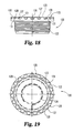
- FIGS. 18 and 21 the details of plug 122 and gear teeth 121 are illustrated.
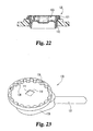
- FIGS. 19 , 20 and 22 illustrate the relationship between plug 122 and overcap 123. These three drawing figures also help to illustrate the relationship between the nineteen (19) gear teeth 121 and overcap 123.
- the nineteen gear teeth 121 are equally-spaced and, between each adjacent pair of gear teeth 121, a recess 125 is defined. This alternating structure and arrangement of teeth 121 and recesses 125 is illustrated in FIGS. 18, 19 and 21 .
- each gear tooth 121 and of each recess 125 is illustrated in FIG. 18 .
- the top plan shape of each gear tooth 121 and of each recess 125 is illustrated in FIGS. 19 and 21 .
- Each gear tooth 121 has diverging sides 127 moving from outer surface 128 radially inwardly to the radial base or root surface 129 of each.
- the matching, inverse shape of each recess 125 includes converging sides (radially inwardly) 127 that correspond to the diverging sides of the corresponding gear tooth 121.
- the upper surfaces 130 of each gear tooth 121 are coplanar and collectively define the uppermost surface of the plug 122.
- the axial height of each gear tooth 121 is defined as the distance from the axial base 131 to the upper surface 130.
- Each gear tooth 121 includes axially diverting sides moving in the direction from the upper surface 130 to the axial base 131.
- socket wrench 135 is identical to socket wrench 82 with the exception of the part-hemispherical recesses 85 now being replaced by gear teeth recesses 136.
- the handles 137 and 108 and the ratchet mechanisms at the distal ends 138 and 109 are identical.
- the square openings and square drive posts are identical. The only difference is to replace the part-hemispherical recesses 85 that match projections 76 with gear teeth recesses 136 that match the number, size, shape, and spacing of gear teeth 121.
- Socket wrench 135 is used to advance and remove plug 122 as desired, particularly when overcap 123 is attached such that the interior forms of the plug are not accessible.
- the first embodiment of FIGS. 11-16 uses projections 76 that are raised in an axial direction and thus the socket fit is axial.
- the recesses 85 fit downwardly over the projections 76. This is why gaps in the annular ring form on plug 60 in terms of the number of projections 76 is not an issue of the interfit, only an issue of torque.
- the second embodiment of FIGS. 18-22 uses dentate shapes (gear teeth 121) that project radially outwardly. Since the recesses 125 between adjacent teeth are open from the top, the socket wrench 135 still fits down over the gear teeth. If a full annular ring of gear teeth 121 is not provided, gaps resulting from the elimination of a tooth or teeth will not interfere with the socket recesses 136.
Landscapes
- Engineering & Computer Science (AREA)
- Mechanical Engineering (AREA)
- Closures For Containers (AREA)
Applications Claiming Priority (1)
| Application Number | Priority Date | Filing Date | Title |
|---|---|---|---|
| US12/028,341 US8061543B2 (en) | 2008-02-08 | 2008-02-08 | Plastic plug with overcap, including wrench and method |
Publications (1)
| Publication Number | Publication Date |
|---|---|
| EP2088089A1 true EP2088089A1 (fr) | 2009-08-12 |
Family
ID=40568581
Family Applications (1)
| Application Number | Title | Priority Date | Filing Date |
|---|---|---|---|
| EP09250253A Withdrawn EP2088089A1 (fr) | 2008-02-08 | 2009-01-30 | Bouchon en plastique doté d'un surbouchage incluant une clé et procédé |
Country Status (5)
| Country | Link |
|---|---|
| US (2) | US8061543B2 (fr) |
| EP (1) | EP2088089A1 (fr) |
| AU (1) | AU2009200351A1 (fr) |
| CA (1) | CA2651149A1 (fr) |
| MX (1) | MX2009001010A (fr) |
Families Citing this family (14)
| Publication number | Priority date | Publication date | Assignee | Title |
|---|---|---|---|---|
| US9578765B2 (en) * | 2008-07-25 | 2017-02-21 | Robroy Industries, Inc. | Hole plug device |
| USD638194S1 (en) | 2010-06-11 | 2011-05-17 | Carpathian Industries, LLC | Plug having a tool insert opening with a non-circular constant diameter cross-section |
| USD671384S1 (en) | 2012-05-03 | 2012-11-27 | Carpathian Industries, LLC | Tool adaptor for a plug with a non-circular constant diameter cross-section |
| US20140061250A1 (en) * | 2012-08-28 | 2014-03-06 | Robert Turcotte | Recessed Container Closure and Method of Increasing Advertising Space on a Container using a Recessed Container Closure |
| WO2017091761A1 (fr) | 2015-11-25 | 2017-06-01 | Yeti Coolers, Llc | Contenant isolant comportant des panneaux d'isolation sous vide et procédé |
| US11472608B2 (en) * | 2016-11-21 | 2022-10-18 | Joanna Shields | Container fitting |
| FR3064162B1 (fr) * | 2017-03-27 | 2019-03-22 | L'oreal | Capsule de fermeture pour dispositif de conditionnement d'un produit, notamment d'un produit cosmetique |
| USD821824S1 (en) | 2017-05-16 | 2018-07-03 | Yeti Coolers, Llc | Insulating device |
| CN207780654U (zh) * | 2017-07-10 | 2018-08-28 | 中兴通讯股份有限公司 | 转轴连接装置和多屏移动终端设备 |
| US11970313B2 (en) | 2018-12-12 | 2024-04-30 | Yeti Coolers, Llc | Insulating container |
| US10766672B2 (en) | 2018-12-12 | 2020-09-08 | Yeti Coolers, Llc | Insulating container |
| WO2020252143A1 (fr) * | 2019-06-11 | 2020-12-17 | Rieke Llc | Couvercle pour fûts |
| ES2789151B2 (es) * | 2020-04-23 | 2021-09-15 | Pujolasos S L | Tapón reciclable para envases |
| USD1040617S1 (en) | 2022-05-12 | 2024-09-03 | Yeti Coolers, Llc | Insulating container |
Citations (5)
| Publication number | Priority date | Publication date | Assignee | Title |
|---|---|---|---|---|
| US1845078A (en) * | 1930-07-24 | 1932-02-16 | Draper Mfg Co | Container and sealing means therefor |
| US5862936A (en) * | 1996-09-27 | 1999-01-26 | Sonoco Products & Company | Bung for a pressure vessel |
| WO2000050311A1 (fr) * | 1999-02-25 | 2000-08-31 | Royal Packaging Industries Van Leer N.V. | Fermetures de contenant inviolables |
| WO2001038177A2 (fr) * | 1999-11-19 | 2001-05-31 | Rieke Corporation | Couvercle de surbouchage inviolable pour fut |
| EP2017185A2 (fr) * | 2007-07-17 | 2009-01-21 | Rieke Corporation | Bouchon en plastique avec surbouchage |
Family Cites Families (65)
| Publication number | Priority date | Publication date | Assignee | Title |
|---|---|---|---|---|
| US1645675A (en) * | 1926-03-13 | 1927-10-18 | Warner Bros | Bung for metal receptacles |
| US1656228A (en) * | 1927-05-06 | 1928-01-17 | American Flange & Mfg Company | Container and sealing means therefor |
| US1982144A (en) * | 1931-11-07 | 1934-11-27 | American Flange & Mfg Company | Closure device for metallic container opening |
| US1997203A (en) * | 1932-11-16 | 1935-04-09 | American Flange & Mfg | Closure structure for containers |
| US2962185A (en) * | 1958-03-05 | 1960-11-29 | Jerome S Heisler | Plastic closure plug and container flange plug assembly |
| US3122261A (en) * | 1962-03-26 | 1964-02-25 | American Flange & Mfg | Capseals for container closures |
| US3187860A (en) | 1963-01-24 | 1965-06-08 | Chicago Pneumatic Tool Co | Portable nut runner having automatic speed change and automatic shut-off |
| GB1256081A (en) | 1968-03-11 | 1971-12-08 | Lucas Industries Ltd | Ultrasonic welding tools |
| US3405837A (en) * | 1967-04-26 | 1968-10-15 | Greif Bros Cooperage Corp | Ratchet type cap |
| US3556332A (en) * | 1969-06-12 | 1971-01-19 | Sidney M Libit | Child-resistant closures |
| US3684125A (en) * | 1970-08-07 | 1972-08-15 | American Flange & Mfg | Container closure having sealing cap and fastening ring |
| US3811174A (en) | 1971-01-18 | 1974-05-21 | Buckeye Forge | Method of assembling closure member for metal containers |
| FR2135055B1 (fr) | 1971-05-04 | 1975-04-18 | Lancesseur Francois | |
| US3744654A (en) * | 1971-08-02 | 1973-07-10 | H Bromberg | Safety closure device |
| US3845872A (en) * | 1973-04-09 | 1974-11-05 | E Towns | Containers and safety closure therefor |
| US3817420A (en) | 1972-07-26 | 1974-06-18 | R Heisler | Plastic container with plug-type plastic cover |
| US3891118A (en) | 1973-07-02 | 1975-06-24 | American Flange & Mfg | Plastic bonded closure |
| JPS5550119Y2 (fr) * | 1974-03-04 | 1980-11-21 | ||
| US4002259A (en) | 1975-10-06 | 1977-01-11 | Kerr Glass Manufacturing Corporation | Safety closure |
| US4105135A (en) * | 1977-02-18 | 1978-08-08 | American Flange & Manufacturing Co. Inc. | Closure plug |
| US4310102A (en) | 1978-04-03 | 1982-01-12 | The Continental Group, Inc. | Closure for pressure container |
| US4164304A (en) * | 1978-05-30 | 1979-08-14 | The Continental Group, Inc. | Closure for steel drums with blow molded liners |
| US4211333A (en) * | 1978-06-05 | 1980-07-08 | Merck & Co., Inc. | Tamperproof container |
| US4306357A (en) * | 1978-06-05 | 1981-12-22 | Merck & Co., Inc. | Tamperproof container |
| FR2430367A2 (fr) * | 1978-07-06 | 1980-02-01 | Fontanaud Robert | Capsule porte-reducteur |
| FR2439721A1 (fr) | 1978-10-27 | 1980-05-23 | Seprosy | Dispositif de bouchage de recipients presentant un col |
| US4236646A (en) * | 1978-11-02 | 1980-12-02 | Baxter Travenol Laboratories, Inc. | Closure for pharmaceutical containers |
| US4281972A (en) * | 1979-01-31 | 1981-08-04 | Carrier Corporation | Apparatus for controlling the performance of a motor compressor |
| US4271972A (en) | 1979-07-24 | 1981-06-09 | Container Corporation Of America | Tamperproof overcap |
| US4359169A (en) * | 1981-08-28 | 1982-11-16 | Container Corporation Of America | Container end closure arrangement |
| US4416661A (en) | 1981-12-24 | 1983-11-22 | Cutter Laboratories, Inc. | Injection site for fluids |
| US4588103A (en) * | 1985-09-18 | 1986-05-13 | Rieke Corporation | Closure construction having back-up support means |
| WO1988004262A1 (fr) | 1986-12-02 | 1988-06-16 | Dai Nippon Insatsu Kabushiki Kaisha | Recipient pourvu d'un couvercle metallique et production dudit recipient |
| US4711365A (en) * | 1987-02-09 | 1987-12-08 | Fomby Kenneth A | Container and closure assembly with folding sealing ribs |
| US4779766A (en) * | 1987-02-13 | 1988-10-25 | Seaquist Closures | Dispensing closure for a container |
| GB2203135B (en) | 1987-04-08 | 1990-08-08 | Metal Box Plc | Plug lid for a container |
| USD315309S (en) | 1987-06-04 | 1991-03-12 | Rieke Corporation | Plastic internally threaded container insert |
| US4872570A (en) * | 1987-11-10 | 1989-10-10 | Harding Claude J | Tamper indicator |
| US4795058A (en) * | 1988-01-11 | 1989-01-03 | The United States Of America As Represented By The Secretary Of The Air Force | Shipping container port assembly |
| US5005718A (en) * | 1988-08-04 | 1991-04-09 | Van Blarcom Closures, Inc. | Tamper-evident child resistant closure device |
| US5080245A (en) * | 1990-03-22 | 1992-01-14 | The West Company Incorporated | Bidirectional scoring |
| US5215220A (en) * | 1991-04-30 | 1993-06-01 | Courtesy Corporation | Tamper evident closure with dispensing spout and integral opening member |
| GB9322908D0 (en) | 1993-11-06 | 1993-12-22 | Lawson Mardon M I Ltd | Tamper-evident cap for a keg spear |
| US5680953A (en) | 1993-11-16 | 1997-10-28 | Rieke Corporation | Plastic drum closure |
| DE4410790A1 (de) | 1994-03-28 | 1995-10-05 | Berg Jacob Gmbh Co Kg | Schraubkappe mit Anschweißring |
| US5971183A (en) * | 1995-12-15 | 1999-10-26 | The Procter & Gamble Company | Tamper-evident leak-tight closure for containers |
| US5735419A (en) | 1996-02-16 | 1998-04-07 | Crown Cork & Seal Company, Inc. | Resealable plastic snap-fit closure with anti-tamper function |
| US5829611A (en) * | 1996-10-07 | 1998-11-03 | Creative Packaging Corp. | Tamper-evident overcap |
| US5875907A (en) * | 1997-06-17 | 1999-03-02 | Aptargroup, Inc. | Tamper-evident dispensing closure for a container |
| US6981602B2 (en) * | 1997-08-01 | 2006-01-03 | Portola Packaging, Inc. | Tamper evident bottle cap |
| US5971195A (en) * | 1997-11-03 | 1999-10-26 | Taco Bell Corporation | Container closure containing game piece |
| US5996833A (en) * | 1997-11-05 | 1999-12-07 | Sonoco Development, Inc. | Tamper evident dust cover for a drum bung |
| US6247605B1 (en) | 1998-05-22 | 2001-06-19 | Yoshino Kogyosho Co., Ltd. | Inner plug and cap for liquid injection containers, and jig used to fix cap to inner plug |
| DE29821764U1 (de) | 1998-12-08 | 1999-02-25 | Mühlhoff, Hartmut, Dipl.-Ing., 50767 Köln | Behälterverschluss |
| US20020112867A1 (en) | 2001-02-21 | 2002-08-22 | Ming-Qun Tseng | Air passage shifting device for a pneumatic tool |
| US20050242018A1 (en) * | 2001-08-01 | 2005-11-03 | Teledyne Isco, Inc. | Disposable chromatographic columns |
| US6726048B2 (en) | 2002-09-09 | 2004-04-27 | American Flange & Mfg. Co., Inc | Drum plug and seal |
| DE10319428A1 (de) * | 2003-04-29 | 2004-11-18 | Bericap Gmbh & Co. Kg | Verschlußkappe mit Abdeckscheibe |
| US6968968B2 (en) * | 2003-09-15 | 2005-11-29 | Rieke Corporation | Container closure assembly with snap-on overcap |
| US20050133508A1 (en) | 2003-12-17 | 2005-06-23 | Landis Russel J. | Tamper evident lid welded to a container |
| US20050258129A1 (en) * | 2004-05-21 | 2005-11-24 | Peter Model | Tamper-proof closure/seal for containers, particularly wine bottles |
| CA2582382A1 (fr) * | 2004-10-07 | 2006-04-20 | West Pharmaceutical Services, Inc. | Fermeture pour recipeint |
| USD533329S1 (en) | 2004-10-22 | 2006-12-05 | Rieke Corporation | Threaded flange for installation into a container head |
| US7568585B2 (en) * | 2004-11-16 | 2009-08-04 | Rieke Corporation | Plastic, snap-on capseal |
| US7735665B2 (en) * | 2005-02-18 | 2010-06-15 | Rexam Closure Systems Inc. | Child-resistant flip-top dispensing closure, package and method of manufacture |
-
2008
- 2008-02-08 US US12/028,341 patent/US8061543B2/en not_active Expired - Fee Related
-
2009
- 2009-01-22 CA CA002651149A patent/CA2651149A1/fr not_active Abandoned
- 2009-01-26 MX MX2009001010A patent/MX2009001010A/es active IP Right Grant
- 2009-01-30 AU AU2009200351A patent/AU2009200351A1/en not_active Abandoned
- 2009-01-30 EP EP09250253A patent/EP2088089A1/fr not_active Withdrawn
-
2010
- 2010-08-25 US US12/868,035 patent/US8066139B2/en not_active Expired - Fee Related
Patent Citations (5)
| Publication number | Priority date | Publication date | Assignee | Title |
|---|---|---|---|---|
| US1845078A (en) * | 1930-07-24 | 1932-02-16 | Draper Mfg Co | Container and sealing means therefor |
| US5862936A (en) * | 1996-09-27 | 1999-01-26 | Sonoco Products & Company | Bung for a pressure vessel |
| WO2000050311A1 (fr) * | 1999-02-25 | 2000-08-31 | Royal Packaging Industries Van Leer N.V. | Fermetures de contenant inviolables |
| WO2001038177A2 (fr) * | 1999-11-19 | 2001-05-31 | Rieke Corporation | Couvercle de surbouchage inviolable pour fut |
| EP2017185A2 (fr) * | 2007-07-17 | 2009-01-21 | Rieke Corporation | Bouchon en plastique avec surbouchage |
Also Published As
| Publication number | Publication date |
|---|---|
| US8061543B2 (en) | 2011-11-22 |
| US8066139B2 (en) | 2011-11-29 |
| CA2651149A1 (fr) | 2009-08-08 |
| US20090200259A1 (en) | 2009-08-13 |
| AU2009200351A1 (en) | 2009-08-27 |
| US20100314391A1 (en) | 2010-12-16 |
| MX2009001010A (es) | 2009-08-28 |
Similar Documents
| Publication | Publication Date | Title |
|---|---|---|
| US8061543B2 (en) | Plastic plug with overcap, including wrench and method | |
| AU600846B2 (en) | Tamper-evident buttress plug closure | |
| AU2013285690B2 (en) | A closure assembly and a container provided with a closure assembly | |
| EP1772391B1 (fr) | Récipient metallique pour boissos comprenant un manchon de goulot | |
| CA2392222C (fr) | Couvercle de surbouchage inviolable pour fut | |
| EP3286101B1 (fr) | Capuchons de fermeture | |
| EP2782841B1 (fr) | Fermeture inviolable | |
| EP2017185A2 (fr) | Bouchon en plastique avec surbouchage | |
| EP0779227A1 (fr) | Ensemble de fermeture avec goulotte de décharge escamotable | |
| US20170072790A1 (en) | Closure assembly for fuel tank filler neck | |
| EP1514806A2 (fr) | Ensemble de fermeture pour récipient, ayant une capsule de surbouchage | |
| WO2021015809A1 (fr) | Couvercle de pince de retenue à rupture de verrouillage | |
| US20140299569A1 (en) | Closure band for containers | |
| GB2067699A (en) | Tamper-proof fastening | |
| EP1534595A2 (fr) | Capsule a vis inviolable | |
| US4228915A (en) | Fuel cap with antirotation feature between cover and skirt portions | |
| EP4516686A1 (fr) | Bouchon de bouteille anti-retrait par chauffage, et structure de fixation pour corps principal interne de bouchon de bouteille et col de bouteille | |
| US4625889A (en) | Replaceable, crimp-on, threaded closure for plastic container | |
| US9527380B2 (en) | Cap-installation signal system for filler neck cap | |
| RU125558U1 (ru) | Укупорочное устройство | |
| WO2007049969A1 (fr) | Moyens d’extraction pour element connecteur d’un accouplement et moyens de protection pour l’element connecteur | |
| US20040160057A1 (en) | Base tee connection | |
| JP5454932B2 (ja) | 容器用の注出具 | |
| JPH0891403A (ja) | 閉止装置 | |
| JPH08133313A (ja) | 閉止装置 |
Legal Events
| Date | Code | Title | Description |
|---|---|---|---|
| PUAI | Public reference made under article 153(3) epc to a published international application that has entered the european phase |
Free format text: ORIGINAL CODE: 0009012 |
|
| AK | Designated contracting states |
Kind code of ref document: A1 Designated state(s): AT BE BG CH CY CZ DE DK EE ES FI FR GB GR HR HU IE IS IT LI LT LU LV MC MK MT NL NO PL PT RO SE SI SK TR |
|
| AX | Request for extension of the european patent |
Extension state: AL BA RS |
|
| AKX | Designation fees paid | ||
| REG | Reference to a national code |
Ref country code: DE Ref legal event code: 8566 |
|
| STAA | Information on the status of an ep patent application or granted ep patent |
Free format text: STATUS: THE APPLICATION IS DEEMED TO BE WITHDRAWN |
|
| 18D | Application deemed to be withdrawn |
Effective date: 20100213 |