EP2088095A2 - Vorrichtung zur Behandlung Schüttgütern, insbesondere von Tabak - Google Patents
Vorrichtung zur Behandlung Schüttgütern, insbesondere von Tabak Download PDFInfo
- Publication number
- EP2088095A2 EP2088095A2 EP08011570A EP08011570A EP2088095A2 EP 2088095 A2 EP2088095 A2 EP 2088095A2 EP 08011570 A EP08011570 A EP 08011570A EP 08011570 A EP08011570 A EP 08011570A EP 2088095 A2 EP2088095 A2 EP 2088095A2
- Authority
- EP
- European Patent Office
- Prior art keywords
- cell
- wheels
- openings
- region
- rotation
- Prior art date
- Legal status (The legal status is an assumption and is not a legal conclusion. Google has not performed a legal analysis and makes no representation as to the accuracy of the status listed.)
- Granted
Links
Images
Classifications
-
- A—HUMAN NECESSITIES
- A24—TOBACCO; CIGARS; CIGARETTES; SIMULATED SMOKING DEVICES; SMOKERS' REQUISITES
- A24B—MANUFACTURE OR PREPARATION OF TOBACCO FOR SMOKING OR CHEWING; TOBACCO; SNUFF
- A24B3/00—Preparing tobacco in the factory
- A24B3/04—Humidifying or drying tobacco bunches or cut tobacco
-
- A—HUMAN NECESSITIES
- A24—TOBACCO; CIGARS; CIGARETTES; SIMULATED SMOKING DEVICES; SMOKERS' REQUISITES
- A24B—MANUFACTURE OR PREPARATION OF TOBACCO FOR SMOKING OR CHEWING; TOBACCO; SNUFF
- A24B3/00—Preparing tobacco in the factory
-
- A—HUMAN NECESSITIES
- A24—TOBACCO; CIGARS; CIGARETTES; SIMULATED SMOKING DEVICES; SMOKERS' REQUISITES
- A24B—MANUFACTURE OR PREPARATION OF TOBACCO FOR SMOKING OR CHEWING; TOBACCO; SNUFF
- A24B3/00—Preparing tobacco in the factory
- A24B3/12—Steaming, curing, or flavouring tobacco
-
- B—PERFORMING OPERATIONS; TRANSPORTING
- B65—CONVEYING; PACKING; STORING; HANDLING THIN OR FILAMENTARY MATERIAL
- B65G—TRANSPORT OR STORAGE DEVICES, e.g. CONVEYORS FOR LOADING OR TIPPING, SHOP CONVEYOR SYSTEMS OR PNEUMATIC TUBE CONVEYORS
- B65G53/00—Conveying materials in bulk through troughs, pipes or tubes by floating the materials or by flow of gas, liquid or foam
- B65G53/34—Details
- B65G53/40—Feeding or discharging devices
- B65G53/46—Gates or sluices, e.g. rotary wheels
- B65G53/4608—Turnable elements, e.g. rotary wheels with pockets or passages for material
- B65G53/4625—Turnable elements, e.g. rotary wheels with pockets or passages for material with axis of turning perpendicular to flow
- B65G53/4633—Turnable elements, e.g. rotary wheels with pockets or passages for material with axis of turning perpendicular to flow the element having pockets, rotated from charging position to discharging position, i.e. discrete flow
-
- B—PERFORMING OPERATIONS; TRANSPORTING
- B65—CONVEYING; PACKING; STORING; HANDLING THIN OR FILAMENTARY MATERIAL
- B65G—TRANSPORT OR STORAGE DEVICES, e.g. CONVEYORS FOR LOADING OR TIPPING, SHOP CONVEYOR SYSTEMS OR PNEUMATIC TUBE CONVEYORS
- B65G65/00—Loading or unloading
- B65G65/30—Methods or devices for filling or emptying bunkers, hoppers, tanks, or like containers, of interest apart from their use in particular chemical or physical processes or their application in particular machines, e.g. not covered by a single other subclass
- B65G65/34—Emptying devices
- B65G65/40—Devices for emptying otherwise than from the top
- B65G65/48—Devices for emptying otherwise than from the top using other rotating means, e.g. rotating pressure sluices in pneumatic systems
- B65G65/4881—Devices for emptying otherwise than from the top using other rotating means, e.g. rotating pressure sluices in pneumatic systems rotating about a substantially horizontal axis
-
- F—MECHANICAL ENGINEERING; LIGHTING; HEATING; WEAPONS; BLASTING
- F26—DRYING
- F26B—DRYING SOLID MATERIALS OR OBJECTS BY REMOVING LIQUID THEREFROM
- F26B25/00—Details of general application not covered by group F26B21/00 or F26B23/00
- F26B25/001—Handling, e.g. loading or unloading arrangements
- F26B25/002—Handling, e.g. loading or unloading arrangements for bulk goods
-
- F—MECHANICAL ENGINEERING; LIGHTING; HEATING; WEAPONS; BLASTING
- F26—DRYING
- F26B—DRYING SOLID MATERIALS OR OBJECTS BY REMOVING LIQUID THEREFROM
- F26B2200/00—Drying processes and machines for solid materials characterised by the specific requirements of the drying goods
- F26B2200/22—Tobacco leaves
Definitions
- the invention relates to a device for the treatment of bulk materials, in particular of tobacco, with at least one rotary valve whose housing has its cells periodically occlusive and again releasing connection openings.
- Such devices are used for the temporary formation of closed chamber systems, for example, to increase the volume of rib section and Blattschnitttabaken, for moistening tobacco ribs, cloves and DIET tobaccos, for flavoring Thomastabaken, for loosening and mixing Thomastabaken, for recycling committee cigarettes or for Drying purposes are used.
- the treatment is carried out by means of working fluids, which are introduced together with the bulk material in the closed chamber systems.
- the feeding of the untreated bulk material and the discharge of the treated bulk material is carried out regularly on Schwing devisrinnen which are associated with the connection openings of the closed chamber system.
- the known devices for the treatment of bulk materials however, have the disadvantage that in the deterioration occurring in the cell adhesions of bulk material disturbing the treatment process of the bulk material and finally can even cause a complete sealing of the rotary valve.
- the invention is therefore an object of the invention to provide a device of the type mentioned, with the growth of in the Abrasion occurring adhesions of bulk material in the cells of the rotary valve is reliably prevented.
- the inventive device for the treatment of bulk materials is characterized in that the rotary valve has at least two cell wheels with interlocking cell wings.
- the cell wheels can thus be moved only with mutually opposite directions of rotation, wherein the cell wings of one of the cell wheels free the wing interspaces of the cell wings of the other cell wheel of adhesions.
- the bulk material supplied to the device as a bulk material flow is portioned at the cell wings and strigleust in the wing interstices in the form of individual bulk material portions. In the case of wear occurring adhesions of bulk material are thus stripped after the wetting of each bulk material portion and recycled portionwise into the untreated bulk material flow.
- the cell wings not only serve as sluice organs, but also act as broaching organs, with which an increase of occurring during the abrasion adhesions of bulk material is reliably prevented.
- disturbances of the treatment process are avoided and caused by cleaning measures downtime is significantly reduced.
- the treatment of the bulk material is automatic and includes the automatic stripping of the adhesions and the automatic return of the stripped adhesions in the bulk flow, so that manual intervention and thus contacts of the bulk material with pathogenic germs and bacteria are advantageously avoided.
- connection openings is aligned with the engagement region of the intermeshing cell wings.
- a direction of rotation in which unscrew the cell wings out of their engagement area and simultaneously counter-rotating the port opening formed as a feed opening, there is an automatic and ongoing division of the bulk material portions on two lock paths which are specific to the cell wheels.
- This has the advantage that can be stripped from one of the lock paths resulting adhesions to the other Schleusweg.
- the lock movements are used on the one hand for automatic or automatic further transport of the individual bulk material portions and on the other hand for the automatic stripping of the adhesions occurring during the wear.
- the housing has inlet regions formed between the connection openings, in which supply openings for a working fluid are arranged.
- the required due to the supply of the working fluid pressure equalization can be done via the gap between the cell wings and the housing.
- the individual bulk material portions are exposed to the working fluid during the schleusens.
- the duration of treatment of the bulk material portion which is lost during a transfer operation is thus dependent on the duration of a single transfer operation.
- the duration of the lock operations can be influenced by the number of revolutions of the cell wheels, the size of the cell wheels or by a vertical arrangement of several devices according to the invention.
- working fluids in particular gases, liquids and mixtures thereof, but especially water or solvent-containing vapors are used.
- the housing has outlet regions formed between the connection openings, in which discharge openings for the working fluid are arranged.
- the discharge openings have a size that reduces the passage of individual bulk material particles to a minimum.
- each housing region temporarily closing off a cell has at least one partial section of an outlet region and at least one partial section of an inlet region.
- the single cell thus acts as a washing chamber, which is flowed through by the working fluid under the formation of turbulences.
- the outlet regions and inlet regions have an alternating arrangement relative to one another with respect to the direction of rotation of the cellular wheel, so that the flow path experiences a continuous change in its course as a result of the rotation of the cellular wheel. The constant change in the course of the flow path leads to a lasting improvement in the treatment process.
- the inlet and outlet areas as well as by the arrangement of the inlet and outlet areas to each other abrupt or swelling changes in the Strömungswegverdocument can be generated.
- the sum of all flow cross sections of the discharge openings is smaller than the sum of all flow cross sections of the supply openings.
- the cross-sectional sums of feed openings to discharge openings have a ratio of about 1: 3.
- each outlet region and each inlet region is assigned at least one pressure equalization chamber. This serves for the uniform flow load of the outlet and inlet regions and in particular also for the combination of the inlet and outlet openings arranged in an inlet or an outlet region onto a common supply nozzle.
- the supply openings are formed as injection nozzles, through which the working fluid is sprayed or sprayed in a fixed direction.
- the turbulence occurring is characterized by continuously rotating angle of attack, which is caused by the rotational movements of the rotating cell wheels with respect to the fixed injection nozzles.
- the rotating angle of attack prevent the formation of Verzwirbelungen especially long-fiber bulk materials.
- the supply openings are designed as hole or grid structures arranged in the entry area of the housing.
- the feed openings are preferably associated with a pressure generator, with which the working fluid is injected into the cells.
- swirling also includes the mixing, mixing and mixing of a bulk material portion with the working fluid.
- the cells each have a rounded cell bottom and two planar cell edges, wherein the cell edges are formed as tangential extensions of the cell bottom.
- the rounding of the cell bottom serves to minimize the gap between the rounded cell bottoms of one cell wheel and the free ends of the cell wings of the other cell wheel.
- the injection nozzles are advantageously set so that the working fluid is deflected in the form of individual free jets on the rounded cell bottoms. The rounding process depends on the diameter of the cell wheels and the center distance between the cell wheels.
- a particularly extensive prevention of the growth of adhesions is achieved when the smallest distance of the rounded cell bottom to the axis of rotation of its cell wheel plus half the diameter of the other cell wheel corresponds approximately to the center distance between the axes of rotation of the cell wheels.
- the two cell wheels In order to keep the gap dimension constant during the dynamic process, ie during rotation of the cell wheels, over a maximum running distance, the two cell wheels have approximately the same diameter, with this advantageously about 5/7 of the center distance corresponds between the axes of rotation of the cell wheels.
- the radius of the rounded cell bottoms is advantageously about 3/25 of the axial distance between the axes of rotation of the cellular wheels.
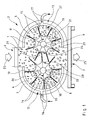
- the Fig. 1 shows a device according to the invention for the treatment of tobacco 1 with a rotary valve 2, the housing 3 has its cells 4, 5 periodically closing and again releasing connection openings 6, 7.
- the rotary feeder 2 has two cell wheels 8, 9 with interlocking cell wings 10, 11.
- the connection opening 6 is designed as a charging opening and is aligned with the engagement region of the intermeshing cell wings 9, 10.
- the housing 3 has two inlet regions 12, 13 formed between the connection openings 6, 7, in which supply openings 14, 15 for a working fluid 16, 17 are arranged.
- the cells 4, 5 each have a rounded cell bottom 18, 19 and two planar-surface cell edges 20, 21, wherein the cell edges 20, 21 are formed as tangential extensions of the cell bottom 18, 19.
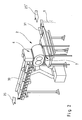
- the Fig. 2 shows a perspective view of the device according to the invention according to Fig. 1 in an application example.
- the connection openings 6, 7 of the rotary feeder 2 are assigned two vibrating conveyor troughs 30, 31, on which the tobacco 1 in the form of the bulk material flow 25, 25 'is forwarded.
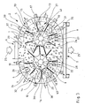
- the Fig. 3 also shows a device according to the invention for the treatment of tobacco 1 with a rotary valve 2, the housing 3 has its cells 4, 5 periodically closing and again releasing connection openings 6, 7.
- the housing 3 here also has two inlet regions 12, 13 formed between the connection openings 6, 7, in which supply openings 14, 15 for a working fluid 16, 17 are arranged.
- the housing 3 in this second embodiment between the connection openings 6, 7 formed outlet regions 32, 33 in which discharge openings 34, 35 are arranged for the working fluid 16, 17.
- a cell 4, 5 occluding region of the housing 3 has at least a portion of an outlet region 32, 33 and at least a portion of an inlet region 12, 13, so that the cells 4, 5 act as rinsing chambers.
- Each outlet region 32, 33 and each inlet region 12, 13 is associated with a pressure compensation chamber 36, 37, the merging of arranged in a single inlet region 12 and 13 supply ports 14 and 15 or the merging arranged in a single outlet region 32 and 33, respectively Abrawö réelleen 34 and 35 on a common supply pipe 38, 39 is used.
- the arrows 40, 41 indicate the direction of rotation of the cell wheels 8, 9. All arrows bearing no reference symbolize the flow direction of the working fluid 16, 17. The same components are provided with the same reference numerals.
Landscapes
- Engineering & Computer Science (AREA)
- Mechanical Engineering (AREA)
- General Engineering & Computer Science (AREA)
- Manufacture Of Tobacco Products (AREA)
- Physical Or Chemical Processes And Apparatus (AREA)
Abstract
Description
- Die Erfindung betrifft eine Vorrichtung zur Behandlung von Schüttgütern, insbesondere von Tabak, mit wenigstens einer Zellenradschleuse, deren Gehäuse ihre Zellen periodisch verschließende und wieder freigebende Anschlußöffnungen aufweist.
- Derartige Vorrichtungen dienen der temporären Ausbildung geschlossener Kammersysteme, die beispielsweise zur Volumenvergrößerung von Rippenschnitt- und Blattschnitttabaken, zum Anfeuchten von Tabakrippen, Nelken und DIET-Tabaken, zum Flavorisieren von Schnitttabaken, zum Auflockern und Mischen von Schnitttabaken, zum Recyceln von Ausschuß-Zigaretten oder für Trocknungszwecke eingesetzt werden. Die Behandlung erfolgt mittels Arbeitsfluiden, welche zusammen mit dem Schüttgut in die geschlossenen Kammersysteme eingebracht werden. Die Zuführung des unbehandelten Schüttgutes sowie die Abführung des behandelten Schüttgutes erfolgt regelmäßig auf Schwingförderrinnen welche den Anschlußöffnungen des geschlossenen Kammersystems zugeordnet sind. Die bekannten Vorrichtungen zur Behandlung von Schüttgütern haben jedoch den Nachteil, daß bei der Verschleusung in den Zellen auftretende Anhaftungen von Schüttgut den Behandlungsprozeß des Schüttgutes nachhaltig stören und schließlich sogar ein vollständiges Dichtsetzen der Zellenradschleuse verursachen können.
- Der Erfindung liegt deshalb die Aufgabe zugrunde, eine Vorrichtung der eingangs genannten Gattung aufzuzeigen, mit der das Anwachsen von bei der Verschleusung auftretenden Anhaftungen von Schüttgut in den Zellen der Zellenradschleuse zuverlässig verhindert ist.
- Diese Aufgabe ist erfindungsgemäß durch eine Vorrichtung mit den Merkmalen des Patentanspruches 1 gelöst. Vorteilhafte Weiterbildungen der Erfindung sind in den Unteransprüchen angegeben.
- Die erfindungsgemäße Vorrichtung zur Behandlung von Schüttgütern zeichnet sich dadurch aus, daß die Zellenradschleuse wenigstens zwei Zellenräder mit ineinandergreifenden Zellflügeln aufweist. Die Zellenräder können somit nur mit zueinander entgegengesetztem Drehsinn bewegt werden, wobei die Zellflügel eines der Zellenräder die Flügelzwischenräume der Zellflügel des jeweils anderen Zellenrades von Anhaftungen befreien. Das der Vorrichtung als Schüttgutstrom zugeführte Schüttgut wird an den Zellflügeln portioniert und in den Flügelzwischenräumen in Form einzelner Schüttgutportionen verschleust. Bei der Verschleusung auftretende Anhaftungen von Schüttgut werden somit nach dem Verschleusen einer jeden Schüttgutportion abgestreift und portionsweise in den unbehandelten Schüttgutstrom zurückgeführt. Damit dienen die Zellflügel nicht nur als Schleusorgane, sondern fungieren zusätzlich als Räumorgane, mit welchen ein Anwachsen von bei der Verschleusung auftretenden Anhaftungen aus Schüttgut zuverlässig verhindert ist. Außerdem sind Störungen des Behandlungsprozesses vermieden und durch Reinigungsmaßnahmen hervorgerufene Betriebsausfallzeiten sind maßgeblich reduziert. Die Behandlung des Schüttgutes erfolgt automatisch und umfaßt das selbsttätige Abstreifen der Anhaftungen sowie die selbsttätige Rückführung der abgestreiften Anhaftungen in den Schüttgutstrom, so daß manuelle Eingriffe und damit auch Kontakte des Schüttgutes mit pathogenen Keimen und Bakterien vorteilhaft vermieden sind.
- Nach einer ersten Weiterbildung der erfindungsgemäßen Vorrichtung ist wenigstens eine der Anschlußöffnungen auf den Eingriffsbereich der ineinandergreifenden Zellflügel ausgerichtet. Bei einer Drehrichtung, bei dem die Zellflügel aus ihrem Eingriffsbereich herausdrehen und gleichzeitig der als Beschickungsöffnung ausgebildeten Anschlußöffnung entgegendrehen, erfolgt eine selbsttätige und fortwährende Aufteilung der Schüttgutportionen auf zwei den Zellenrädern eigene Schleuswege. Das hat den Vorteil, daß aus einem der Schleuswege resultierende Anhaftungen an dem jeweils anderen Schleusweg abgestreift werden können. Dadurch werden die Schleusbewegungen einerseits zum automatischen bzw. selbsttätigen Weitertransport der einzelnen Schüttgutportionen und andererseits zum selbsttätigen Abstreifen der bei der Verschleusung auftretenden Anhaftungen genutzt.
- Nach einer nächsten Weiterbildung der Erfindung weist das Gehäuse zwischen den Anschlußöffnungen ausgebildete Eintrittsbereiche auf, in welchen Zuführöffnungen für ein Arbeitsfluid angeordnet sind. Der wegen der Zuführung des Arbeitsfluides erforderliche Druckausgleich kann über die Spaltmaße zwischen den Zellenflügeln und dem Gehäuse erfolgen. Auf diese Weise werden die einzelnen Schüttgutportionen dem Arbeitsfluid während des Verschleusens ausgesetzt. Die Behandlungsdauer der mit einem Schleusvorgang verschleusten Schüttgutportion ist damit von der Zeitdauer eines einzelnen Schleusvorganges abhängig. Die Zeitdauer der Schleusvorgänge kann über die Drehzahl der Zellenräder, die Größe der Zellenräder oder über eine vertikale Aneinanderreihung mehrerer erfindungsgemäßer Vorrichtungen beeinflußt werden. Als Arbeitsfluide werden insbesondere Gase, Flüssigkeiten sowie deren Gemische, insbesondere jedoch wasser- oder lösungsmittelhaltige Dämpfe eingesetzt.
- Bei Zuführung größerer Mengen eines Arbeitsfluides, insbesondere bei der Zuführung von Trockenluft, ist es von Vorteil, wenn das Gehäuse zwischen den Anschlußöffnungen ausgebildete Austrittsbereiche aufweist, in welchen Abführöffnungen für das Arbeitsfluid angeordnet sind. Die Abführöffnungen weisen eine Größe auf, die das Passieren von einzelnen Schüttgutteilchen auf ein Minimum reduziert.
- Um eine möglichst kurze und gleichzeitig vollständige Behandlung des Schüttgutes zu erwirken, ist es von besonderem Vorteil, wenn die Schüttgutportionen und das Arbeitsfluid während des Verschleusens miteinander verwirbelt werden. Dazu weist jeder zeitweise eine Zelle verschließende Gehäusebereich wenigstens einen Teilabschnitt eines Austrittsbereiches sowie wenigstens einen Teilabschnitt eines Eintrittsbereiches auf. Die einzelne Zelle fungiert damit als Spülraum, welcher von dem Arbeitsfluid unter der Ausbildung von Verwirbelungen durchströmt wird. Die Austrittsbereiche und Eintrittsbereiche weisen bezogen auf die Umlaufrichtung des Zellenrades eine alternierende Anordnung zueinander auf, so daß der Strömungsweg durch die Rotation des Zellenrades eine fortwährende Änderung seines Verlaufes erfährt. Die ständige Änderung des Strömungswegverlaufes hat eine nachhaltige Verbesserung des Behandlungsprozesses zur Folge. Durch die Formgebung der Ein- und Austrittsbereiche sowie durch die Anordnung der Ein- und Austrittsbereiche zueinander können abrupte oder auch schwellende Wechsel der Strömungswegverläufe erzeugt werden. Um zu verhindern, daß das Schüttgut die Abführöffnungen der Austrittsbereiche durch die dort auftretende Sogwirkung dichtsetzt, ist die Summe aller Strömungsquerschnitte der Abführöffnungen kleiner als die Summe aller Strömungsquerschnitte der Zuführöffnungen. Insbesondere weisen die Querschnittssummen von Zuführöffnungen zu Abführöffnungen ein Verhältnis von etwa 1:3 auf.
- Nach einer nächsten Weiterbildung der Erfindung ist jedem Austrittsbereich und jedem Eintrittsbereich wenigstens eine Druckausgleichskammer zugeordnet. Diese dient der gleichmäßigen Strömungsbelastung der Aus- und Eintrittsbereiche und insbesondere auch der Zusammenführung der in einem Eintritts- oder einem Austrittsbereich angeordneten Zu- und Abführöffnungen auf einen gemeinsamen Versorgungsstutzen.
- Nach einer anderen Weiterbildung der Erfindung ist vorgesehen, daß die Zuführöffnungen als Einspritzdüsen ausgebildet sind, durch welche hindurch das Arbeitsfluid in eine festgesetzte Richtung gespritzt oder gesprüht wird. Die dabei auftretende Verwirbelung ist durch sich fortwährend drehende Anströmwinkel gekennzeichnet, welche durch die Drehbewegungen der rotierenden Zellenräder in Bezug auf die feststehenden Einspritzdüsen hervorgerufen wird. Die sich drehenden Anströmwinkel verhindern insbesondere bei langfaserigen Schüttgütern die Entstehung von Verzwirbelungen. Im einfachsten Fall sind die Zuführöffnungen jedoch als im Eintrittsbereich des Gehäuses angeordnete Loch- oder Gitterstrukturen ausgebildet. Den Zuführöffnungen ist vorzugsweise ein Druckerzeuger zugeordnet, mit welchem das Arbeitsfluid in die Zellen eingespritzt wird. Das Verwirbeln umfaßt im Rahmen dieser Erfindung auch das Vermischen, Vermengen und Verrühren einer Schüttgutportion mit dem Arbeitsfluid.
- Eine verbesserte Verhinderung des Anwachsens von bei der Verschleusung auftretenden Anhaftungen ist dadurch erreicht, daß die Zellen jeweils einen abgerundeten Zellenboden sowie zwei planflächige Zellenflanken aufweisen, wobei die Zellenflanken als tangentiale Erweiterungen des Zellenbodens ausgebildet sind. Der Rundungsverlauf des Zellenbodens dient der Spaltminimierung zwischen den abgerundeten Zellenböden des einen Zellenrades und den freien Enden der Zellflügel des jeweils anderen Zellenrades. Die Einspritzdüsen sind mit Vorteil derart eingestellt das Arbeitsfluid in Form einzelner Freistrahlen an den abgerundeten Zellenböden abgelenkt wird. Der Rundungsverlauf ist dabei von dem Durchmesser der Zellenräder sowie dem Achsabstand zwischen den Zellenrädern abhängig.
- Eine besonders weitgehende Verhinderung des Anwachsens von Anhaftungen ist erreicht, wenn der kleinste Abstand des abgerundeten Zellenbodens zur Drehachse seines Zellenrades zuzüglich dem halben Durchmesser des jeweils anderen Zellenrades etwa dem Achsabstand zwischen den Drehachsen der Zellenräder entspricht. Um das Spaltmaß während des dynamischen Prozesses, also bei Rotation der Zellenräder, über eine maximale Laufstrecke hinweg konstant zu halten, weisen die beiden Zellenräder etwa den gleichen Durchmesser auf, wobei dieser mit Vorteil etwa 5/7 des Achsabstandes zwischen den Drehachsen der Zellenräder entspricht. Außerdem beträgt der Radius der abgerundeten Zellenböden mit Vorteil etwa 3/25 des Achsabstandes zwischen den Drehachsen der Zellenräder.
- Selbstverständlich liegt es im Rahmen der Erfindung, die freien Außenkanten der Zellflügel mit weichelastischen Lippen zu versehen, welche an den abgerundeten Zellenböden abgleiten und diese vorteilhaft auch von feinsten Anhaftungen befreien.
- Ein Ausführungsbeispiel der Erfindung, aus dem sich weitere erfinderische Merkmale ergeben, ist in der Zeichnung dargestellt. Es zeigen:
- Fig. 1:
- eine Seitenansicht der erfindungsgemäßen Vorrichtung im Mittelschnitt gemäß einem ersten Ausführungsbeispiel;
- Fig. 2:
- eine perspektivische Darstellung der Vorrichtung gemäß
Fig. 1 in einem Anwendungsbeispiel; und - Fig. 3:
- eine teilgeschnittene Seitenansicht der Vorrichtung im Mittelschnitt gemäß einem zweiten Ausführungsbeispiel.
- Die
Fig. 1 zeigt eine erfindungsgemäße Vorrichtung zur Behandlung von Tabak 1 mit einer Zellenradschleuse 2, deren Gehäuse 3 ihre Zellen 4, 5 periodisch verschließende und wieder freigebende Anschlußöffnungen 6, 7 aufweist. Außerdem weist die Zellenradschleuse 2 zwei Zellenräder 8, 9 mit ineinandergreifenden Zellflügeln 10, 11 auf. Die Anschlußöffnung 6 ist als Beschickungsöffnung ausgebildet und ist auf den Eingriffsbereich der ineinandergreifenden Zellflügel 9, 10 ausgerichtet. Das Gehäuse 3 weist zwei zwischen den Anschlußöffnungen 6, 7 ausgebildete Eintrittsbereiche 12, 13 auf, in welchen Zuführöffnungen 14, 15 für ein Arbeitsfluid 16, 17 angeordnet sind. Die Zellen 4, 5 weisen jeweils einen abgerundeten Zellenboden 18, 19 sowie zwei planflächige Zellenflanken 20, 21 auf, wobei die Zellenflanken 20, 21 als tangentiale Erweiterungen des Zellenbodens 18, 19 ausgebildet sind. - Der kleinste Abstand des abgerundeten Zellenbodens 18, 19 zur Drehachse 22, 23 seines Zellenrades 8, 9 zuzüglich dem halben Durchmesser des jeweils anderen Zellenrades 8, 9 abzüglich dem Abstand zwischen den Drehachsen 22, 23 entspricht dem Abziehspalt 24.
- Die Vorrichtung arbeitet wie folgt:
- Ein Tabak 1 enthaltender Schüttgutstrom 25, 25' wird portioniert und in Form einzelner Schüttgutportionen 26, 27 in den Zellen 4, 5 der Zellenradschleuse 2 verschleust. Bei der Verschleusung auftretende Anhaftungen 28, 29 von Tabak 1 werden nach dem Verschleusen einer jeden Schüttgutportion 26, 27 von den Zellflügeln 9, 10 abgestreift und portionsweise in den unbehandelten Schüttgutstrom 25, 25' zurückgeführt. Die Schüttgutportionen 26, 27 werden auf zwei den Zellenrädern 8, 9 eigene Schleuswege aufgeteilt, aufweichen sie einem Arbeitsfluid 16, 17 ausgesetzt werden. Dabei werden die Schüttgutportionen 26, 27 und das Arbeitsfluid 16, 17 miteinander verwirbelt.
- Die
Fig. 2 zeigt eine perspektivische Darstellung der erfindungsgemäßen Vorrichtung gemäßFig. 1 in einem Anwendungsbeispiel. Hier sind den Anschlußöffnungen 6, 7 der Zellenradschleuse 2 zwei Schwingförderrinnen 30, 31 zugeordnet, auf denen der Tabak 1 in Form des Schüttgutstroms 25, 25' weiterbefördert wird. - Die
Fig. 3 zeigt ebenfalls eine erfindungsgemäße Vorrichtung zur Behandlung von Tabak 1 mit einer Zellenradschleuse 2, deren Gehäuse 3 ihre Zellen 4, 5 periodisch verschließende und wieder freigebende Anschlußöffnungen 6, 7 aufweist. Das Gehäuse 3 weist auch hier zwei zwischen den Anschlußöffnungen 6, 7 ausgebildete Eintrittsbereiche 12, 13 auf, in welchen Zuführöffnungen 14, 15 für ein Arbeitsfluid 16, 17 angeordnet sind. Außerdem weist das Gehäuse 3 bei diesem zweiten Ausführungsbeispiel zwischen den Anschlußöffnungen 6, 7 ausgebildete Austrittsbereiche 32, 33 auf in welchen Abführöffnungen 34, 35 für das Arbeitsfluid 16, 17 angeordnet sind. Jeder zeitweise eine Zelle 4, 5 verschließende Bereich des Gehäuses 3 weist wenigstens einen Teilabschnitt eines Austrittsbereiches 32, 33 sowie wenigstens einen Teilabschnitt eines Eintrittsbereiches 12, 13 auf, so daß die Zellen 4, 5 als Spülkammern fungieren. Jedem Austrittsbereich 32, 33 und jedem Eintrittsbereich 12, 13 ist eine Druckausgleichskammer 36, 37 zugeordnet, die der Zusammenführung der in einem einzigen Eintrittsbereich 12 bzw. 13 angeordneten Zuführöffnungen 14 bzw. 15 oder der Zusammenführung der in einem einzigen Austrittsbereich 32 bzw. 33 angeordneten Abführöffnungen 34 bzw. 35 auf einen gemeinsamen Versorgungsstutzen 38, 39 dient. Die Pfeile 40, 41 geben die Drehrichtung der Zellenräder 8, 9 an. Sämtliche keine Bezugszahl tragenden Pfeile symbolisieren die Strömungsrichtung des Arbeitsfluides 16, 17. Gleiche Bauteile sind mit gleichen Bezugszahlen versehen.
Claims (11)
- Vorrichtung zur Behandlung von Schüttgütern, insbesondere von Tabak (1), mit wenigstens einer Zellenradschleuse (2), deren Gehäuse (3) ihre Zellen (4, 5) periodisch verschließende und wieder freigebende Anschlußöffnungen (6, 7) aufweist,
dadurch gekennzeichnet,
daß die Zellenradschleuse (2) wenigstens zwei Zellenräder (8,9) mit ineinandergreifenden Zellflügeln (10, 11) aufweist. - Vorrichtung nach Anspruch 1 dadurch gekennzeichnet, daß wenigstens eine der Anschlußöffnungen (6, 7) auf den Eingriffsbereich der ineinandergreifenden Zellflügel (10, 11) ausgerichtet ist.
- Vorrichtung nach Anspruch 1 oder 2, dadurch gekennzeichnet, daß das Gehäuse (3) zwischen den Anschlußöffnungen (6, 7) ausgebildete Eintrittsbereiche (12, 13) aufweist, in welchen Zuführöffnungen (14, 15) für ein Arbeitsfluid (16, 17) angeordnet sind.
- Vorrichtung nach einem der Ansprüche 1 bis 3, dadurch gekennzeichnet, daß das Gehäuse (3) zwischen den Anschlußöffnungen (6, 7) ausgebildete Austrittsbereiche (32, 33) aufweist, in welchen Abführöffnungen (34, 35) für das Arbeitsfluid (16, 17) angeordnet sind.
- Vorrichtung nach Anspruch 4, dadurch gekennzeichnet, daß jeder zeitweise eine Zelle (4, 5) verschließende Bereich des Gehäuses (3) wenigstens einen Teilabschnitt eines Austrittsbereiches (32, 33) sowie wenigstens einen Teilabschnitt eines Eintrittsbereiches (12, 13) aufweist.
- Vorrichtung nach Anspruch 4 oder 5, dadurch gekennzeichnet, daß jedem Austrittsbereich (32, 33) und jedem Eintrittsbereich (12, 13) wenigstens eine Druckausgleichskammer (36, 37) zugeordnet ist.
- Vorrichtung nach einem der Ansprüche 1 bis 6, dadurch gekennzeichnet, daß die Zuführöffnungen (14, 15) als Einspritzdüsen ausgebildet sind.
- Vorrichtung nach einem der Ansprüche 1 bis 7, dadurch gekennzeichnet, daß die Zellen (4, 5) jeweils einen abgerundeten Zellenboden (18, 19) sowie zwei planflächige Zellenflanken (20, 21) aufweisen, wobei die Zellenflanken (20, 21) als tangentiale Erweiterungen des Zellenbodens (18, 19) ausgebildet sind.
- Vorrichtung nach Anspruch 8, dadurch gekennzeichnet, daß der kleinste Abstand des abgerundeten Zellenbodens (18, 19) zur Drehachse (22, 23) seines Zellenrades (8, 9) zuzüglich dem halben Durchmesser des jeweils anderen Zellenrades (8, 9) etwa dem Achsabstand zwischen den Drehachsen (22, 23) der Zellenräder (8, 9) entspricht.
- Vorrichtung nach einem der Ansprüche 1 bis 9, dadurch gekennzeichnet, daß die beiden Zellenräder (8, 9) etwa den gleichen Durchmesser aufweisen, welcher etwa 5/7 des Achsabstandes zwischen den Drehachsen (22, 23) Zellenräder (8, 9) entspricht.
- Vorrichtung nach einem der Ansprüche 8 bis 10, dadurch gekennzeichnet, daß der Radius der abgerundeten Zellenböden (18, 19) etwa 3/25 des Achsabstandes zwischen den Drehachsen (22, 23) der Zellenräder (8, 9) entspricht.
Priority Applications (1)
| Application Number | Priority Date | Filing Date | Title |
|---|---|---|---|
| PL08011570T PL2088095T3 (pl) | 2008-02-08 | 2008-06-26 | Urządzenie do obróbki materiałów sypkich, w szczególności do tytoniu |
Applications Claiming Priority (1)
| Application Number | Priority Date | Filing Date | Title |
|---|---|---|---|
| DE202008001800U DE202008001800U1 (de) | 2008-02-08 | 2008-02-08 | Vorrichtung zur Behandlung von Schüttgütern, insbesondere von Tabak |
Publications (4)
| Publication Number | Publication Date |
|---|---|
| EP2088095A2 true EP2088095A2 (de) | 2009-08-12 |
| EP2088095A3 EP2088095A3 (de) | 2010-01-27 |
| EP2088095B1 EP2088095B1 (de) | 2014-06-04 |
| EP2088095B8 EP2088095B8 (de) | 2014-09-10 |
Family
ID=39326871
Family Applications (1)
| Application Number | Title | Priority Date | Filing Date |
|---|---|---|---|
| EP08011570.2A Active EP2088095B8 (de) | 2008-02-08 | 2008-06-26 | Vorrichtung zur Behandlung von Schüttgütern, insbesondere von Tabak |
Country Status (3)
| Country | Link |
|---|---|
| EP (1) | EP2088095B8 (de) |
| DE (1) | DE202008001800U1 (de) |
| PL (1) | PL2088095T3 (de) |
Cited By (6)
| Publication number | Priority date | Publication date | Assignee | Title |
|---|---|---|---|---|
| EP2218343A1 (de) | 2009-02-13 | 2010-08-18 | Heinen-Köhl Tobacco GmbH | Verfahren und Vorrichtung zur Reinigung von Schüttgut |
| CN112520439A (zh) * | 2020-11-12 | 2021-03-19 | 贵州中烟工业有限责任公司 | 一种制丝车间的贮柜出料流量控制方法及系统 |
| CN112829974A (zh) * | 2021-02-19 | 2021-05-25 | 河北欧卡自动化设备有限公司 | 自动称重分装设备及其称重分装方法 |
| CN112971190A (zh) * | 2021-01-29 | 2021-06-18 | 红云红河烟草(集团)有限责任公司 | 大重九专线连批柔性切换布料暂存工艺储丝储叶装置 |
| CN114893963A (zh) * | 2022-06-06 | 2022-08-12 | 四川省烟草公司广元市公司 | 一种用于烟草农业的高效烘干室 |
| CN117246773A (zh) * | 2023-09-06 | 2023-12-19 | 湖北高森特钢制品股份有限公司 | 一种粉状润滑剂生产用输送机 |
Families Citing this family (3)
| Publication number | Priority date | Publication date | Assignee | Title |
|---|---|---|---|---|
| WO2014142724A1 (en) * | 2013-03-15 | 2014-09-18 | Valmet Ab | Bin for collecting and discharging smaller ligno-cellulosic material |
| DE102013209607A1 (de) * | 2013-05-23 | 2014-11-27 | Hauni Maschinenbau Ag | Trommeltrockner zum Trocknen von Tabak, und entsprechendes Trocknungsverfahren |
| DE102021116375A1 (de) | 2021-03-23 | 2022-09-29 | Streumaster Maschinenbau GmbH | Streuwerk und Streugerät |
Citations (1)
| Publication number | Priority date | Publication date | Assignee | Title |
|---|---|---|---|---|
| DE3005241A1 (de) | 1979-05-10 | 1981-08-20 | Hazemag Dr. E. Andreas GmbH & Co, 4400 Münster | Zellendradschleuse |
Family Cites Families (8)
| Publication number | Priority date | Publication date | Assignee | Title |
|---|---|---|---|---|
| US2907499A (en) * | 1957-04-22 | 1959-10-06 | Pandia Inc | Paper machinery |
| DE1885880U (de) * | 1963-11-20 | 1964-01-09 | Basf Ag | Zellenradschleuse. |
| FR2482568A1 (fr) * | 1980-05-13 | 1981-11-20 | Bernad Saturnin | Extracteur et distributeur rotatif de beton stocke en tremie |
| DE3439274C1 (de) * | 1984-10-26 | 1986-01-23 | Didier Ingenieria y Montajes Industriales, S.A. (DIMISA), Aviles | Füllwagen zur Kohlebeschickung von Horizontalkammer-Verkokungsöfen |
| GB8915824D0 (en) * | 1989-07-11 | 1989-08-31 | Gbe Legg Limited | Apparatus for the even application of liquid and gaseous fluid to vegetable |
| DE19734364A1 (de) * | 1997-08-08 | 1999-02-11 | Hauni Maschinenbau Ag | Verfahren und Vorrichtung zum Aufbringen eines Konditionierungsmediums auf Tabakmaterial |
| GB0000596D0 (en) * | 2000-01-13 | 2000-03-01 | Drum Int Ltd | Feed devices |
| WO2003046453A1 (en) * | 2001-11-26 | 2003-06-05 | Japan Tobacco Inc. | Air flow dryer for granular material |
-
2008
- 2008-02-08 DE DE202008001800U patent/DE202008001800U1/de not_active Expired - Lifetime
- 2008-06-26 PL PL08011570T patent/PL2088095T3/pl unknown
- 2008-06-26 EP EP08011570.2A patent/EP2088095B8/de active Active
Patent Citations (1)
| Publication number | Priority date | Publication date | Assignee | Title |
|---|---|---|---|---|
| DE3005241A1 (de) | 1979-05-10 | 1981-08-20 | Hazemag Dr. E. Andreas GmbH & Co, 4400 Münster | Zellendradschleuse |
Cited By (9)
| Publication number | Priority date | Publication date | Assignee | Title |
|---|---|---|---|---|
| EP2218343A1 (de) | 2009-02-13 | 2010-08-18 | Heinen-Köhl Tobacco GmbH | Verfahren und Vorrichtung zur Reinigung von Schüttgut |
| CN112520439A (zh) * | 2020-11-12 | 2021-03-19 | 贵州中烟工业有限责任公司 | 一种制丝车间的贮柜出料流量控制方法及系统 |
| CN112971190A (zh) * | 2021-01-29 | 2021-06-18 | 红云红河烟草(集团)有限责任公司 | 大重九专线连批柔性切换布料暂存工艺储丝储叶装置 |
| CN112971190B (zh) * | 2021-01-29 | 2023-03-03 | 红云红河烟草(集团)有限责任公司 | 大重九专线连批柔性切换布料暂存工艺储丝储叶装置 |
| CN112829974A (zh) * | 2021-02-19 | 2021-05-25 | 河北欧卡自动化设备有限公司 | 自动称重分装设备及其称重分装方法 |
| CN114893963A (zh) * | 2022-06-06 | 2022-08-12 | 四川省烟草公司广元市公司 | 一种用于烟草农业的高效烘干室 |
| CN114893963B (zh) * | 2022-06-06 | 2023-10-24 | 四川省烟草公司广元市公司 | 一种用于烟草农业的高效烘干室 |
| CN117246773A (zh) * | 2023-09-06 | 2023-12-19 | 湖北高森特钢制品股份有限公司 | 一种粉状润滑剂生产用输送机 |
| CN117246773B (zh) * | 2023-09-06 | 2024-05-10 | 湖北高森特钢制品股份有限公司 | 一种粉状润滑剂生产用输送机 |
Also Published As
| Publication number | Publication date |
|---|---|
| DE202008001800U1 (de) | 2008-04-24 |
| EP2088095B1 (de) | 2014-06-04 |
| PL2088095T3 (pl) | 2014-11-28 |
| EP2088095A3 (de) | 2010-01-27 |
| EP2088095B8 (de) | 2014-09-10 |
Similar Documents
| Publication | Publication Date | Title |
|---|---|---|
| EP2088095B1 (de) | Vorrichtung zur Behandlung Schüttgütern, insbesondere von Tabak | |
| DE69515507T2 (de) | Vorrichtung und system zum waschen von behältern | |
| DE69729578T2 (de) | Flüssigkeitsabgabevorrichtung und -verfahren | |
| EP1622711B1 (de) | Verfahren und vorrichtung zum aufbringen von flüssigkeiten in eine feststoffströmung eines strahlschichtapparates | |
| DE2707809C3 (de) | Vorrichtung zum Überziehen von Granulat | |
| DE2822950C3 (de) | Vorrichtung zum Abläsen von Staub von rohrartigen Filterelementen | |
| EP0160661B1 (de) | Vorrichtung zum pneumatischen und hydraulischen fördern von schüttgut | |
| EP0185316A2 (de) | Dragiertrommel | |
| DE2558304B2 (de) | Mischkopf für reaktionsfähige, flüssige Komponenten | |
| EP0476300B1 (de) | Verfahren und Vorrichtung zur Adsorption bzw. Chemiesorption von gasförmigen Bestandteilen aus einem Gasstrom | |
| DE2438818A1 (de) | Vorrichtung zum kontinuierlichen beleimen von fasern | |
| DE3937538C2 (de) | Verfahren und Maschine zur gleichzeitigen Herstellung von zwei kontinuierlichen Zigarettensträngen | |
| DE102016115577A1 (de) | Vakuum- und/oder Druck-Trommelfiltervorrichtung | |
| DE3641639A1 (de) | Regelbare auslaufduese fuer pneumatische dosierfoerderer | |
| DE102018208930A1 (de) | Vorrichtung und Verfahren zur Herstellung und Behandlung von Granulat sowie Adapterstutzen zur Verbindung eines ein Granulat erzeugenden Granulators und eines Fluidisierungsapparates | |
| DE4442538C2 (de) | Doppel-Strang-Zigaretten-Herstellungs-Vorrichtung | |
| DE3339432A1 (de) | Maschine zur gleichzeitigen herstellung von fortlaufenden zigarettenstraengen | |
| DE2303430B2 (de) | Vorrichtung zum Reinigen von gasförmigen Stoffen, welche Farbstoff, Lack bzw. Zellulose enthalten | |
| DE2904121C2 (de) | ||
| EP2811850B1 (de) | Vorrichtung und verfahren zum bilden mindestens eines strangs der tabak verarbeitenden industrie sowie verteilervorrichtung zum beschicken einer strangmaschine | |
| EP0192803B1 (de) | Zellenradschleuse zum Abscheiden feinteiliger Feststoffe aus einem Luftstrom | |
| EP0571576B1 (de) | Dosierverfahren und vorrichtung zu dessen durchführung | |
| DE3818911A1 (de) | Sorptionseinrichtung zum reinigen von abgasen | |
| DE19544208C1 (de) | Auswaschvorrichtung für Restmaterial wie Restbeton od. dgl. | |
| DE3209412C2 (de) | Vorrichtung zur Reinhaltung von Stützisolatoren in Elektroabscheidern |
Legal Events
| Date | Code | Title | Description |
|---|---|---|---|
| PUAI | Public reference made under article 153(3) epc to a published international application that has entered the european phase |
Free format text: ORIGINAL CODE: 0009012 |
|
| AK | Designated contracting states |
Kind code of ref document: A2 Designated state(s): AT BE BG CH CY CZ DE DK EE ES FI FR GB GR HR HU IE IS IT LI LT LU LV MC MT NL NO PL PT RO SE SI SK TR |
|
| AX | Request for extension of the european patent |
Extension state: AL BA MK RS |
|
| PUAL | Search report despatched |
Free format text: ORIGINAL CODE: 0009013 |
|
| AK | Designated contracting states |
Kind code of ref document: A3 Designated state(s): AT BE BG CH CY CZ DE DK EE ES FI FR GB GR HR HU IE IS IT LI LT LU LV MC MT NL NO PL PT RO SE SI SK TR |
|
| AX | Request for extension of the european patent |
Extension state: AL BA MK RS |
|
| 17P | Request for examination filed |
Effective date: 20100714 |
|
| AKX | Designation fees paid |
Designated state(s): AT BE BG CH CY CZ DE DK EE ES FI FR GB GR HR HU IE IS IT LI LT LU LV MC MT NL NO PL PT RO SE SI SK TR |
|
| AXX | Extension fees paid |
Extension state: RS Payment date: 20100714 Extension state: BA Payment date: 20100714 Extension state: MK Payment date: 20100714 Extension state: AL Payment date: 20100714 |
|
| RAP1 | Party data changed (applicant data changed or rights of an application transferred) |
Owner name: KOEHL MASCHINENBAU AG |
|
| 17Q | First examination report despatched |
Effective date: 20130507 |
|
| GRAP | Despatch of communication of intention to grant a patent |
Free format text: ORIGINAL CODE: EPIDOSNIGR1 |
|
| INTG | Intention to grant announced |
Effective date: 20140204 |
|
| GRAS | Grant fee paid |
Free format text: ORIGINAL CODE: EPIDOSNIGR3 |
|
| GRAA | (expected) grant |
Free format text: ORIGINAL CODE: 0009210 |
|
| AK | Designated contracting states |
Kind code of ref document: B1 Designated state(s): AT BE BG CH CY CZ DE DK EE ES FI FR GB GR HR HU IE IS IT LI LT LU LV MC MT NL NO PL PT RO SE SI SK TR |
|
| AX | Request for extension of the european patent |
Extension state: AL BA MK RS |
|
| REG | Reference to a national code |
Ref country code: GB Ref legal event code: FG4D Free format text: NOT ENGLISH |
|
| REG | Reference to a national code |
Ref country code: CH Ref legal event code: EP |
|
| REG | Reference to a national code |
Ref country code: AT Ref legal event code: REF Ref document number: 670954 Country of ref document: AT Kind code of ref document: T Effective date: 20140615 |
|
| REG | Reference to a national code |
Ref country code: IE Ref legal event code: FG4D Free format text: LANGUAGE OF EP DOCUMENT: GERMAN |
|
| REG | Reference to a national code |
Ref country code: DE Ref legal event code: R096 Ref document number: 502008011820 Country of ref document: DE Effective date: 20140717 |
|
| REG | Reference to a national code |
Ref country code: NL Ref legal event code: VDEP Effective date: 20140604 |
|
| PG25 | Lapsed in a contracting state [announced via postgrant information from national office to epo] |
Ref country code: LT Free format text: LAPSE BECAUSE OF FAILURE TO SUBMIT A TRANSLATION OF THE DESCRIPTION OR TO PAY THE FEE WITHIN THE PRESCRIBED TIME-LIMIT Effective date: 20140604 Ref country code: GR Free format text: LAPSE BECAUSE OF FAILURE TO SUBMIT A TRANSLATION OF THE DESCRIPTION OR TO PAY THE FEE WITHIN THE PRESCRIBED TIME-LIMIT Effective date: 20140905 Ref country code: FI Free format text: LAPSE BECAUSE OF FAILURE TO SUBMIT A TRANSLATION OF THE DESCRIPTION OR TO PAY THE FEE WITHIN THE PRESCRIBED TIME-LIMIT Effective date: 20140604 Ref country code: NO Free format text: LAPSE BECAUSE OF FAILURE TO SUBMIT A TRANSLATION OF THE DESCRIPTION OR TO PAY THE FEE WITHIN THE PRESCRIBED TIME-LIMIT Effective date: 20140904 Ref country code: CY Free format text: LAPSE BECAUSE OF FAILURE TO SUBMIT A TRANSLATION OF THE DESCRIPTION OR TO PAY THE FEE WITHIN THE PRESCRIBED TIME-LIMIT Effective date: 20140604 |
|
| REG | Reference to a national code |
Ref country code: LT Ref legal event code: MG4D |
|
| PG25 | Lapsed in a contracting state [announced via postgrant information from national office to epo] |
Ref country code: LV Free format text: LAPSE BECAUSE OF FAILURE TO SUBMIT A TRANSLATION OF THE DESCRIPTION OR TO PAY THE FEE WITHIN THE PRESCRIBED TIME-LIMIT Effective date: 20140604 Ref country code: HR Free format text: LAPSE BECAUSE OF FAILURE TO SUBMIT A TRANSLATION OF THE DESCRIPTION OR TO PAY THE FEE WITHIN THE PRESCRIBED TIME-LIMIT Effective date: 20140604 Ref country code: SE Free format text: LAPSE BECAUSE OF FAILURE TO SUBMIT A TRANSLATION OF THE DESCRIPTION OR TO PAY THE FEE WITHIN THE PRESCRIBED TIME-LIMIT Effective date: 20140604 |
|
| REG | Reference to a national code |
Ref country code: PL Ref legal event code: T3 |
|
| PG25 | Lapsed in a contracting state [announced via postgrant information from national office to epo] |
Ref country code: PT Free format text: LAPSE BECAUSE OF FAILURE TO SUBMIT A TRANSLATION OF THE DESCRIPTION OR TO PAY THE FEE WITHIN THE PRESCRIBED TIME-LIMIT Effective date: 20141006 Ref country code: SK Free format text: LAPSE BECAUSE OF FAILURE TO SUBMIT A TRANSLATION OF THE DESCRIPTION OR TO PAY THE FEE WITHIN THE PRESCRIBED TIME-LIMIT Effective date: 20140604 Ref country code: EE Free format text: LAPSE BECAUSE OF FAILURE TO SUBMIT A TRANSLATION OF THE DESCRIPTION OR TO PAY THE FEE WITHIN THE PRESCRIBED TIME-LIMIT Effective date: 20140604 Ref country code: ES Free format text: LAPSE BECAUSE OF FAILURE TO SUBMIT A TRANSLATION OF THE DESCRIPTION OR TO PAY THE FEE WITHIN THE PRESCRIBED TIME-LIMIT Effective date: 20140604 Ref country code: RO Free format text: LAPSE BECAUSE OF FAILURE TO SUBMIT A TRANSLATION OF THE DESCRIPTION OR TO PAY THE FEE WITHIN THE PRESCRIBED TIME-LIMIT Effective date: 20140604 Ref country code: CZ Free format text: LAPSE BECAUSE OF FAILURE TO SUBMIT A TRANSLATION OF THE DESCRIPTION OR TO PAY THE FEE WITHIN THE PRESCRIBED TIME-LIMIT Effective date: 20140604 |
|
| REG | Reference to a national code |
Ref country code: CH Ref legal event code: PL |
|
| PG25 | Lapsed in a contracting state [announced via postgrant information from national office to epo] |
Ref country code: IS Free format text: LAPSE BECAUSE OF FAILURE TO SUBMIT A TRANSLATION OF THE DESCRIPTION OR TO PAY THE FEE WITHIN THE PRESCRIBED TIME-LIMIT Effective date: 20141004 Ref country code: NL Free format text: LAPSE BECAUSE OF FAILURE TO SUBMIT A TRANSLATION OF THE DESCRIPTION OR TO PAY THE FEE WITHIN THE PRESCRIBED TIME-LIMIT Effective date: 20140604 |
|
| REG | Reference to a national code |
Ref country code: DE Ref legal event code: R097 Ref document number: 502008011820 Country of ref document: DE |
|
| REG | Reference to a national code |
Ref country code: IE Ref legal event code: MM4A |
|
| PG25 | Lapsed in a contracting state [announced via postgrant information from national office to epo] |
Ref country code: MC Free format text: LAPSE BECAUSE OF FAILURE TO SUBMIT A TRANSLATION OF THE DESCRIPTION OR TO PAY THE FEE WITHIN THE PRESCRIBED TIME-LIMIT Effective date: 20140604 |
|
| PLBE | No opposition filed within time limit |
Free format text: ORIGINAL CODE: 0009261 |
|
| STAA | Information on the status of an ep patent application or granted ep patent |
Free format text: STATUS: NO OPPOSITION FILED WITHIN TIME LIMIT |
|
| PG25 | Lapsed in a contracting state [announced via postgrant information from national office to epo] |
Ref country code: LI Free format text: LAPSE BECAUSE OF NON-PAYMENT OF DUE FEES Effective date: 20140630 Ref country code: CH Free format text: LAPSE BECAUSE OF NON-PAYMENT OF DUE FEES Effective date: 20140630 Ref country code: DK Free format text: LAPSE BECAUSE OF FAILURE TO SUBMIT A TRANSLATION OF THE DESCRIPTION OR TO PAY THE FEE WITHIN THE PRESCRIBED TIME-LIMIT Effective date: 20140604 Ref country code: IE Free format text: LAPSE BECAUSE OF NON-PAYMENT OF DUE FEES Effective date: 20140626 |
|
| REG | Reference to a national code |
Ref country code: FR Ref legal event code: ST Effective date: 20150407 |
|
| 26N | No opposition filed |
Effective date: 20150305 |
|
| GBPC | Gb: european patent ceased through non-payment of renewal fee |
Effective date: 20140904 |
|
| PG25 | Lapsed in a contracting state [announced via postgrant information from national office to epo] |
Ref country code: FR Free format text: LAPSE BECAUSE OF NON-PAYMENT OF DUE FEES Effective date: 20140804 |
|
| REG | Reference to a national code |
Ref country code: DE Ref legal event code: R097 Ref document number: 502008011820 Country of ref document: DE Effective date: 20150305 |
|
| PG25 | Lapsed in a contracting state [announced via postgrant information from national office to epo] |
Ref country code: GB Free format text: LAPSE BECAUSE OF NON-PAYMENT OF DUE FEES Effective date: 20140904 Ref country code: SI Free format text: LAPSE BECAUSE OF FAILURE TO SUBMIT A TRANSLATION OF THE DESCRIPTION OR TO PAY THE FEE WITHIN THE PRESCRIBED TIME-LIMIT Effective date: 20140604 |
|
| REG | Reference to a national code |
Ref country code: AT Ref legal event code: MM01 Ref document number: 670954 Country of ref document: AT Kind code of ref document: T Effective date: 20140626 |
|
| PG25 | Lapsed in a contracting state [announced via postgrant information from national office to epo] |
Ref country code: AT Free format text: LAPSE BECAUSE OF NON-PAYMENT OF DUE FEES Effective date: 20140626 |
|
| PG25 | Lapsed in a contracting state [announced via postgrant information from national office to epo] |
Ref country code: MT Free format text: LAPSE BECAUSE OF FAILURE TO SUBMIT A TRANSLATION OF THE DESCRIPTION OR TO PAY THE FEE WITHIN THE PRESCRIBED TIME-LIMIT Effective date: 20140604 |
|
| PG25 | Lapsed in a contracting state [announced via postgrant information from national office to epo] |
Ref country code: BG Free format text: LAPSE BECAUSE OF FAILURE TO SUBMIT A TRANSLATION OF THE DESCRIPTION OR TO PAY THE FEE WITHIN THE PRESCRIBED TIME-LIMIT Effective date: 20140604 |
|
| PG25 | Lapsed in a contracting state [announced via postgrant information from national office to epo] |
Ref country code: TR Free format text: LAPSE BECAUSE OF FAILURE TO SUBMIT A TRANSLATION OF THE DESCRIPTION OR TO PAY THE FEE WITHIN THE PRESCRIBED TIME-LIMIT Effective date: 20140604 Ref country code: LU Free format text: LAPSE BECAUSE OF NON-PAYMENT OF DUE FEES Effective date: 20140626 Ref country code: HU Free format text: LAPSE BECAUSE OF FAILURE TO SUBMIT A TRANSLATION OF THE DESCRIPTION OR TO PAY THE FEE WITHIN THE PRESCRIBED TIME-LIMIT; INVALID AB INITIO Effective date: 20080626 Ref country code: BE Free format text: LAPSE BECAUSE OF FAILURE TO SUBMIT A TRANSLATION OF THE DESCRIPTION OR TO PAY THE FEE WITHIN THE PRESCRIBED TIME-LIMIT Effective date: 20140630 |
|
| PGFP | Annual fee paid to national office [announced via postgrant information from national office to epo] |
Ref country code: PL Payment date: 20170413 Year of fee payment: 10 |
|
| PG25 | Lapsed in a contracting state [announced via postgrant information from national office to epo] |
Ref country code: PL Free format text: LAPSE BECAUSE OF NON-PAYMENT OF DUE FEES Effective date: 20180626 |
|
| PGFP | Annual fee paid to national office [announced via postgrant information from national office to epo] |
Ref country code: DE Payment date: 20250620 Year of fee payment: 18 |
|
| PGFP | Annual fee paid to national office [announced via postgrant information from national office to epo] |
Ref country code: IT Payment date: 20250630 Year of fee payment: 18 |