EP2088228B1 - Aiguille à clapet - Google Patents
Aiguille à clapet Download PDFInfo
- Publication number
- EP2088228B1 EP2088228B1 EP08002103A EP08002103A EP2088228B1 EP 2088228 B1 EP2088228 B1 EP 2088228B1 EP 08002103 A EP08002103 A EP 08002103A EP 08002103 A EP08002103 A EP 08002103A EP 2088228 B1 EP2088228 B1 EP 2088228B1
- Authority
- EP
- European Patent Office
- Prior art keywords
- needle
- tongue
- latch
- spring element
- spring
- Prior art date
- Legal status (The legal status is an assumption and is not a legal conclusion. Google has not performed a legal analysis and makes no representation as to the accuracy of the status listed.)
- Active
Links
Images



Classifications
-
- D—TEXTILES; PAPER
- D04—BRAIDING; LACE-MAKING; KNITTING; TRIMMINGS; NON-WOVEN FABRICS
- D04B—KNITTING
- D04B35/00—Details of, or auxiliary devices incorporated in, knitting machines, not otherwise provided for
- D04B35/02—Knitting tools or instruments not provided for in group D04B15/00 or D04B27/00
- D04B35/04—Latch needles
Definitions
- the invention relates to a latch needle with a needle tongue, in which a tongue spring is integrated.
- Knitting machines or other stitch forming systems are often equipped with latch needles having a tongue spring.
- a tongue spring For example, the DE 10 2004 049 061 A1 such a latch needle.
- the needle body is provided at the end with a hook.
- a tongue slot is provided, in which the needle tongue is pivotally mounted.
- a leaf spring is arranged, which extends longitudinally through the tongue slot and whose ends are held on the needle body.
- the tongue spring presses against the bearing end of the needle tongue and causes the needle tongue in the vicinity of their end positions has two rest positions.
- the needle tongue is in rest position, it is slightly off their final position.
- the DE 101 06 989 C2 shows such a latch needle.
- the tongue spring serves to push the needle tongue away from its end positions resiliently.
- a latch needle with a pivotally mounted tongue known which has a spring leg. This extends away from the tongue bearing.
- the invention On the better removal of lint or other abrasion or dirt out of the tongue slot, the invention has a further advantage. Especially at high production speeds, the occasionally occurring tongue spring loss can be avoided. It can be completely dispensed with an additional tongue spring in the tongue slot.
- the spring element is formed as an integral part of the needle tongue.
- the spring element is thereby captively connected to the needle tongue. Even at high operating speeds, the spring element can not be detached from the needle tongue. It is rather part of the needle tongue and is preferably made of the same material as these.
- the needle slot can now, after he no longer needs tongue tongue, be designed independently of the tongue spring. It is possible to form the needle slot by a plurality of recesses into one another, whereby one or more connections remain between the slot walls. These compounds can on the one hand serve as stops for the needle tongue or its spring element and on the other hand as a stiffening element in order to stabilize the slot walls against each other andlubsteifen the needle.
- the spring element may be formed by a portion of the needle tongue itself.
- one or more spring elements e.g. Leaf spring elements are welded to the needle tongue.
- the needle tongue has a bearing portion and a head.
- the head may be formed as a spoon, for example, to pick up the tip of the hook of the needle.
- the head may be formed by a narrow web which fits into a longitudinal groove of the hook, also referred to as a "zasche".
- the bearing portion and the head may be rigidly connected to one another, while the spring element extends, for example, from the head to the bearing portion and optionally past or around it.
- the spring element may be formed as a leaf spring or spring tongue.
- the spring element may be a U-shaped element which extends around the bearing portion, wherein the two legs of the U-shaped element are connected, for example, to the head of the needle tongue. Thus, it forms a U-shaped bracket that can cushion the tongue in both end positions.
- the spring element springs with respect to the journal of the latch needle in the radial direction.
- connection between the bearing portion and the head of the needle tongue as a spring element, e.g. form as a narrow bridge, which acts as a bending spring.
- a spring element e.g. form as a narrow bridge, which acts as a bending spring.
- the spring stiffness can be adjusted within wide limits. It can be made relatively low, without the spring elements must be cut too thin.
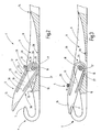
- FIG. 1 illustrates a latch needle 1 for use in a knitting machine, such as a circular knitting machine, a flat knitting machine, or for use in another stitch forming system.
- the latch needle 1 has a needle body 2 which is adapted to be inserted into the needle channel of a needle bed.
- the needle body 2 is provided with a foot 3, which serves to drive the latch needle 1 or its positioning and comes to use in use with a needle lock or other positioning means not shown in detail.
- the needle body 2 forms a shaft which is provided at its free end with a hook 4.
- the hook 4 is associated with a needle tongue 5, which is held pivotally mounted in a tongue slot 6.
- the needle tongue 5 can come into contact with the tip 7 of the hook 4 in an extreme position in order to close the hook interior. It can also pivot far away from the tip 7 to release the hook 4.
- FIG. 2 illustrates the latch needle 1 after FIG. 1 in a different size representation and cut along the tongue slot 6, which is bounded by two slot walls 8, 9.
- the needle slot 6 merges into an opening 11 that extends through the needle back 10.
- the opening 11 is preferably shorter relative to the axial direction of the latch needle 1 than the length of the latch slot 6, which extends at the needle breast 12 from a hook-side end 13 to an opposite end 14.
- the needle tongue 5 is resilient in itself. It has approximately a rectangular flat basic shape, which is bounded by two large flat side surfaces 35 and 36, which are substantially parallel spaced apart, as well as two narrow flat sides, the tongue back 37 and the inner edge 38 of the tongue shaft.
- the flat sides 35 and 36 are connected to each other via the tongue back 37 and the inner edge 38 of the needle tongue. All edges are rounded and smoothed so that damage to the yarn to be processed does not occur or is almost impossible.
- the needle tongue 5 has a head 15 which, when in the closed position as shown in FIG. 3, bears against the hook 4.
- the tip 7 can be absorbed by a spoon portion of the head 5, as it FIG. 3 shows.
- the needle tongue 5 has a tongue shaft, which has at the end remote from the head 15, a bearing portion 16, on which the needle tongue 5 is provided with a bearing opening 17. This preferably extends as a cylindrical bore across the needle tongue 5.
- a pin 18 passes through the bearing opening 17 with little play and thus forms a pivot bearing for the needle tongue 5.
- the pin 18 is connected to the slot walls 8, 9.
- the bearing portion 16 and the head 15 are connected to each other via a rigid web 19.
- the bearing portion 16, the web 19 and the head 15 go seamlessly and integrally into one another.
- a spring element 20 extends away.
- the spring element 20 forms a U-shaped bracket with two straight legs 21, 22, each defining a slot 23, 24 with the web 19.
- a preferably circular arc-shaped connecting portion 25 connects the two legs 21, 22 with each other and leads around the bearing-side end of the bearing portion 16 around. Between both an arcuate slot 26 is present.
- the needle tongue 5 can, as shown, consist of a single metal part, the spring element 20 is formed by the slots 23, 24, 26 are introduced. These slots 23, 24, 26 form a total of a U-shaped recess, for example, with a constant width, which leads around the bearing portion 16 and along the web 19.
- the legs 21, 22 preferably have a uniform respectively perpendicular to the adjacent slot to be measured thickness.
- the parallel to the pin 18 to be measured width of the legs 21, 22 and the connecting portion 25 matches locally preferably with the width of the needle tongue 5 and thus with the distance between the two flat sides 35 and 36.
- the legs 21, 22 and the connecting portion 25 may also have a width deviating from the distance of the two flat sides 35 and 36. For example, they can also have a reduced width for increasing the spring action or for other reasons.
- contact surfaces 27, 28 are preferably provided on both sides of the opening, which are positioned so that the needle tongue 5 comes into contact there before it has reached their respective end position.
- the two contact surfaces 27, 28 are arranged with respect to the needle longitudinal direction in front of and behind the bearing pin 18, which is in direct alignment with the opening 11 or above it (based on the illustration of Figure 2).
- FIG. 4 illustrates the rear rest position of the needle tongue 5.
- the spring element 20 abuts with the outside of its leg 21 on the contact surface 28.
- the head 15 is slightly from needle body 2 from.
- the spring element 20 fulfills the function of a tongue spring as otherwise the separate tongue spring according to latch needles DE 10 2004 049 061 A1 or DE 101 06 989 C2 ,
- the spring element 20 does not obstruct the passage through the tongue slot. Rather, the opening 11 is free. Dirt, dust, abrasion and the like can be led out of the tongue slot 6 easily through the opening 11.
- FIG. 6 also possible to provide the bottom of the tongue slot 6 not only with an opening 11 but optionally also with a plurality of openings.
- a second opening 30 is provided which connects the needle back 10 with the tongue slot 6.
- the openings 11, 30 are mutually separated by a web 31, which the two side cheeks 8, 9 (FIG. FIG. 1 ) connects to each other.
- the contact surface 28 is provided on the web 31.
- the web 19 is slimmer than in the previous embodiments.
- the slots 23, 24, 26 have different sizes and shapes and in turn release the spring element 20.
- the legs 21, 22 can be unequal in length and thicken somewhat towards the head 15. Otherwise, the previous description of the FIGS. 1 to 5 based on the same reference numerals accordingly.
- FIG. 7 A further modification of the latch needle 1 according to the invention is made FIG. 7 seen.
- the web 19 is made so slim (ie, the slots 23, 24 are so wide) that the web 19 itself becomes a spring element.
- the needle tongue 5 thus has two spring elements, namely the spring element 20 consisting of the legs 21, 22nd and the connecting portion 25 and a second spring element 32 formed by the web 19.
- the two spring elements 20, 32 result in a total of a relatively soft spring, which also makes it possible to achieve large distances between the head 15 and the tip 7, when the Needle tongue 5 is in a relaxed rest position.
- the legs 21, 22 and the connecting portion 25 interpreted comparatively stiff, so that the spring action is provided entirely or predominantly alone by the spring element 32.
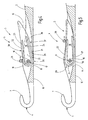
- FIG. 8 illustrates another embodiment of a latch needle with resilient needle tongue 5.
- the peculiarity of the needle tongue 5 is that the spring element 20 is formed by a single spring tongue 33. Of the head 15 extends parallel to the web 19 of the legs 22 which ends in the vicinity of the journal 18. With this configuration, a rest position of the needle tongue 5 according to FIG. 8 reached near the closed position. In reserve, the needle tongue 5 is not sprung. If this should be regarded as an imperfection, this becomes with the embodiment according to FIG. 9 remedied.
- This can be made with reference to the description of the embodiment according to the FIGS. 1 to 5 can be best understood by starting from this description in the connecting portion 25, an interruption 34 is attached. In this interruption 34, the curved ends of the legs 21, 22 face each other at a distance.
- the contact surface 27 is associated with the leg 22.
- the contact surface 28 is associated with the leg 21.
- the latch needle according to the invention has a needle tongue with integrated spring, which is designed as a functional element on the needle tongue. At the needle body and in the tongue slot no separate tongue spring must be accommodated. The spring element is no longer associated with the needle body but the needle tongue. This innovative needle concept is robust and suitable for high-speed use.
Landscapes
- Engineering & Computer Science (AREA)
- Textile Engineering (AREA)
- Knitting Machines (AREA)
Claims (8)
- Aiguille à clapet (1)
comportant un corps d'aiguille (2) sur lequel est monté de façon mobile un clapet d'aiguille (5),
le clapet d'aiguille (5) présentant une section de montage (16) et une tête (15) qui sont reliées l'une à l'autre, et
le clapet d'aiguille (5) comportant au moins un élément formant ressort (20, 32, 33),
caractérisée en ce que
l'élément formant ressort (20, 32, 33) s'étend depuis la tête (15) jusqu'à la section de montage (16). - Aiguille à clapet selon la revendication 1 caractérisée en ce que l'élément formant ressort (20, 32, 33) est réalisé sous forme d'une section du clapet d'aiguille (5).
- Aiguille à clapet selon la revendication 2 caractérisée en ce que la section est constituée du même matériau que le reste du clapet d'aiguille (5) et est reliée à celui-ci d'un seul tenant sans soudure.
- Aiguille à clapet selon la revendication 1 caractérisée en ce que l'élément formant ressort (20) entoure la section de montage (16).
- Aiguille à clapet selon la revendication 1 caractérisée en ce que l'élément formant ressort (33) est un clapet ressort indépendant.
- Aiguille à clapet selon la revendication 1 caractérisée en ce que l'élément formant ressort (32) relie la section de montage (16) à la tête (15).
- Aiguille à clapet selon la revendication 1 caractérisée en ce que l'élément formant ressort (20, 32, 33) est un ressort de fluxion.
- Aiguille à clapet selon la revendication 1 caractérisée en ce que le corps d'aiguille (2) présente une fente (6) pour clapet, dans laquelle le clapet d'aiguille (5) est monté à pivotement, au moins un moyen de butée (27, 28) étant prévu dans la fente de clapet (6) avec lequel moyen de butée vient en contact le clapet d'aiguille (5), avant d'atteindre sa position d'extrémité.
Priority Applications (6)
| Application Number | Priority Date | Filing Date | Title |
|---|---|---|---|
| EP08002103A EP2088228B1 (fr) | 2008-02-05 | 2008-02-05 | Aiguille à clapet |
| JP2009021417A JP4987889B2 (ja) | 2008-02-05 | 2009-02-02 | べら針 |
| CN2009101307251A CN101514509B (zh) | 2008-02-05 | 2009-02-04 | 舌针 |
| TW098103477A TWI409372B (zh) | 2008-02-05 | 2009-02-04 | 舌針 |
| KR1020090008771A KR101083982B1 (ko) | 2008-02-05 | 2009-02-04 | 래치 니들 |
| US12/320,781 US7624598B2 (en) | 2008-02-05 | 2009-02-04 | Latch needle |
Applications Claiming Priority (1)
| Application Number | Priority Date | Filing Date | Title |
|---|---|---|---|
| EP08002103A EP2088228B1 (fr) | 2008-02-05 | 2008-02-05 | Aiguille à clapet |
Publications (2)
| Publication Number | Publication Date |
|---|---|
| EP2088228A1 EP2088228A1 (fr) | 2009-08-12 |
| EP2088228B1 true EP2088228B1 (fr) | 2011-10-19 |
Family
ID=39149153
Family Applications (1)
| Application Number | Title | Priority Date | Filing Date |
|---|---|---|---|
| EP08002103A Active EP2088228B1 (fr) | 2008-02-05 | 2008-02-05 | Aiguille à clapet |
Country Status (6)
| Country | Link |
|---|---|
| US (1) | US7624598B2 (fr) |
| EP (1) | EP2088228B1 (fr) |
| JP (1) | JP4987889B2 (fr) |
| KR (1) | KR101083982B1 (fr) |
| CN (1) | CN101514509B (fr) |
| TW (1) | TWI409372B (fr) |
Families Citing this family (5)
| Publication number | Priority date | Publication date | Assignee | Title |
|---|---|---|---|---|
| EP2604359B1 (fr) * | 2011-12-14 | 2017-06-14 | Groz-Beckert KG | Aiguille à coulisse dotée d'une aiguille à clapet améliorée et sa méthode de fabrication |
| CN102535000B (zh) * | 2011-12-20 | 2013-12-11 | 常州思成凯业精密制针有限公司 | 防尘舌针 |
| JP6930719B2 (ja) * | 2017-02-13 | 2021-09-01 | オルガン針株式会社 | ベラ針 |
| EP3604651A1 (fr) * | 2018-08-03 | 2020-02-05 | Groz-Beckert KG | Aiguille à clapet |
| EP4029979B1 (fr) * | 2021-01-13 | 2025-04-09 | Groz-Beckert KG | Corps d'aiguille, agencement d'aiguille coulissante et métier à mailles jetées |
Family Cites Families (14)
| Publication number | Priority date | Publication date | Assignee | Title |
|---|---|---|---|---|
| DE12490C (de) * | W. BARFUSS in Apolda | Zungennadel zur Anfertigung von Prefsmustern | ||
| US2252302A (en) * | 1937-12-10 | 1941-08-12 | Franklin J Morith | Knitting needle |
| US3050968A (en) * | 1959-06-16 | 1962-08-28 | Masujima Ryozo | Knitting needles |
| JPS4936245U (fr) * | 1972-07-04 | 1974-03-30 | ||
| DE3331031C2 (de) * | 1983-08-27 | 1985-07-11 | Theodor Groz & Söhne & Ernst Beckert Nadelfabrik KG, 7470 Albstadt | Zungennadel für maschenbildende Textilmaschinen |
| JPS60127383U (ja) * | 1984-01-30 | 1985-08-27 | オルガン針株式会社 | メリヤス編針 |
| DE3629334A1 (de) * | 1986-08-28 | 1988-03-10 | Stoll & Co H | Flachstrickmaschine |
| DE3702019C1 (de) * | 1987-01-24 | 1987-09-24 | Groz & Soehne Theodor | Zungennadel fuer maschenbildende Textilmaschinen |
| DE19712124C2 (de) * | 1997-03-22 | 1999-07-01 | Groz Beckert Kg | Zungennadel für maschenbildende Textilmaschinen |
| DE10051029C1 (de) * | 2000-10-14 | 2002-07-11 | Groz Beckert Kg | Zungennadel mit federnder Zungenunterstützung |
| DE10106989C2 (de) | 2001-02-15 | 2003-04-24 | Groz Beckert Kg | Zungennadel mit fixierter Feder |
| DE10232884B4 (de) * | 2002-07-19 | 2004-05-27 | Groz-Beckert Kg | Zungennadel |
| DE10341630B4 (de) * | 2003-09-10 | 2006-11-16 | Groz-Beckert Kg | Zungennadel |
| DE102004049061B4 (de) * | 2004-10-08 | 2006-08-24 | Groz-Beckert Kg | Zungennadel |
-
2008
- 2008-02-05 EP EP08002103A patent/EP2088228B1/fr active Active
-
2009
- 2009-02-02 JP JP2009021417A patent/JP4987889B2/ja not_active Expired - Fee Related
- 2009-02-04 KR KR1020090008771A patent/KR101083982B1/ko not_active Expired - Fee Related
- 2009-02-04 TW TW098103477A patent/TWI409372B/zh active
- 2009-02-04 CN CN2009101307251A patent/CN101514509B/zh not_active Expired - Fee Related
- 2009-02-04 US US12/320,781 patent/US7624598B2/en active Active
Also Published As
| Publication number | Publication date |
|---|---|
| TWI409372B (zh) | 2013-09-21 |
| CN101514509A (zh) | 2009-08-26 |
| TW200951262A (en) | 2009-12-16 |
| US7624598B2 (en) | 2009-12-01 |
| KR20090086036A (ko) | 2009-08-10 |
| CN101514509B (zh) | 2011-11-30 |
| EP2088228A1 (fr) | 2009-08-12 |
| US20090173109A1 (en) | 2009-07-09 |
| KR101083982B1 (ko) | 2011-11-22 |
| JP4987889B2 (ja) | 2012-07-25 |
| JP2009197383A (ja) | 2009-09-03 |
Similar Documents
| Publication | Publication Date | Title |
|---|---|---|
| EP1589136B1 (fr) | Elément de système ayant un ressort freinant | |
| EP2088228A1 (fr) | Aiguille à clapet | |
| EP3168336A1 (fr) | Garniture tout acier | |
| EP2096200A1 (fr) | Aiguille de transfer avec pointe de ressort installée à l'intérieur | |
| EP2999815B1 (fr) | Aguille à coulisse | |
| EP2009160B1 (fr) | Aiguille coupante dotée d'une lame réglable | |
| EP2172584B1 (fr) | Aiguille de machine à tricoter dotée d'un arc à méandre fendu | |
| DE102006004099B3 (de) | Wirkelement, insbesondere Wirknadel einer Kettenwirkmaschine, sowie Wirkmaschinen-Barre | |
| EP2942429B1 (fr) | AIGUILLES à TRICOTER ET BARRE D'AIGUILLES | |
| EP2224048B1 (fr) | Aiguille à clapet dotée d'une goupille axiale rotative | |
| EP1731651B1 (fr) | Aiguille à clapet pour des machines textiles | |
| EP1619282B1 (fr) | Aiguille pour un système formant des mailles | |
| DE19712124C2 (de) | Zungennadel für maschenbildende Textilmaschinen | |
| EP0405085B1 (fr) | Outil pour des machines formant des mailles, notamment des machines à tricoter | |
| EP1743966B1 (fr) | Lisse de tissage pour métier à tisser à grande vitesse | |
| DE10232884B4 (de) | Zungennadel | |
| EP1801276B1 (fr) | Elément de système de tricotage | |
| EP1887117B1 (fr) | Aiguille à clapet pour machine textile à former des mailles | |
| EP3690095B1 (fr) | Aiguille du métier à tricoter et système de tricotage | |
| EP1197591A1 (fr) | Aiguille à clapet avec suport clapet élastique | |
| EP1645670A1 (fr) | Aiguille à clapet | |
| EP1303659A1 (fr) | Aiguille a clapet a tige de clapet abaissee | |
| EP4474554B1 (fr) | Fournisseur de fil | |
| EP4187006B1 (fr) | Outil à tricoter et procédé de fabrication d'un outil à tricoter | |
| DE19521265C2 (de) | Streckwerk für Spinnmaschinen |
Legal Events
| Date | Code | Title | Description |
|---|---|---|---|
| PUAI | Public reference made under article 153(3) epc to a published international application that has entered the european phase |
Free format text: ORIGINAL CODE: 0009012 |
|
| AK | Designated contracting states |
Kind code of ref document: A1 Designated state(s): AT BE BG CH CY CZ DE DK EE ES FI FR GB GR HR HU IE IS IT LI LT LU LV MC MT NL NO PL PT RO SE SI SK TR |
|
| AX | Request for extension of the european patent |
Extension state: AL BA MK RS |
|
| 17P | Request for examination filed |
Effective date: 20090903 |
|
| AKX | Designation fees paid |
Designated state(s): DE IT RO TR |
|
| 17Q | First examination report despatched |
Effective date: 20100803 |
|
| GRAP | Despatch of communication of intention to grant a patent |
Free format text: ORIGINAL CODE: EPIDOSNIGR1 |
|
| GRAS | Grant fee paid |
Free format text: ORIGINAL CODE: EPIDOSNIGR3 |
|
| GRAA | (expected) grant |
Free format text: ORIGINAL CODE: 0009210 |
|
| AK | Designated contracting states |
Kind code of ref document: B1 Designated state(s): DE IT RO TR |
|
| REG | Reference to a national code |
Ref country code: DE Ref legal event code: R096 Ref document number: 502008005208 Country of ref document: DE Effective date: 20111215 |
|
| REG | Reference to a national code |
Ref country code: RO Ref legal event code: EPE |
|
| PLBE | No opposition filed within time limit |
Free format text: ORIGINAL CODE: 0009261 |
|
| STAA | Information on the status of an ep patent application or granted ep patent |
Free format text: STATUS: NO OPPOSITION FILED WITHIN TIME LIMIT |
|
| 26N | No opposition filed |
Effective date: 20120720 |
|
| REG | Reference to a national code |
Ref country code: DE Ref legal event code: R097 Ref document number: 502008005208 Country of ref document: DE Effective date: 20120720 |
|
| PGFP | Annual fee paid to national office [announced via postgrant information from national office to epo] |
Ref country code: RO Payment date: 20240112 Year of fee payment: 17 Ref country code: DE Payment date: 20240229 Year of fee payment: 17 |
|
| PGFP | Annual fee paid to national office [announced via postgrant information from national office to epo] |
Ref country code: TR Payment date: 20240202 Year of fee payment: 17 Ref country code: IT Payment date: 20240111 Year of fee payment: 17 |
|
| REG | Reference to a national code |
Ref country code: DE Ref legal event code: R119 Ref document number: 502008005208 Country of ref document: DE |
|
| PG25 | Lapsed in a contracting state [announced via postgrant information from national office to epo] |
Ref country code: RO Free format text: LAPSE BECAUSE OF NON-PAYMENT OF DUE FEES Effective date: 20250205 |
|
| PG25 | Lapsed in a contracting state [announced via postgrant information from national office to epo] |
Ref country code: DE Free format text: LAPSE BECAUSE OF NON-PAYMENT OF DUE FEES Effective date: 20250902 |
|
| PG25 | Lapsed in a contracting state [announced via postgrant information from national office to epo] |
Ref country code: IT Free format text: LAPSE BECAUSE OF NON-PAYMENT OF DUE FEES Effective date: 20250205 |