EP2088277A2 - Agencement d'étanchéité pour une porte sans seuil - Google Patents
Agencement d'étanchéité pour une porte sans seuil Download PDFInfo
- Publication number
- EP2088277A2 EP2088277A2 EP09405023A EP09405023A EP2088277A2 EP 2088277 A2 EP2088277 A2 EP 2088277A2 EP 09405023 A EP09405023 A EP 09405023A EP 09405023 A EP09405023 A EP 09405023A EP 2088277 A2 EP2088277 A2 EP 2088277A2
- Authority
- EP
- European Patent Office
- Prior art keywords
- sealing
- lever
- housing
- sealing device
- sealing strip
- Prior art date
- Legal status (The legal status is an assumption and is not a legal conclusion. Google has not performed a legal analysis and makes no representation as to the accuracy of the status listed.)
- Granted
Links
Images


Classifications
-
- E—FIXED CONSTRUCTIONS
- E06—DOORS, WINDOWS, SHUTTERS, OR ROLLER BLINDS IN GENERAL; LADDERS
- E06B—FIXED OR MOVABLE CLOSURES FOR OPENINGS IN BUILDINGS, VEHICLES, FENCES OR LIKE ENCLOSURES IN GENERAL, e.g. DOORS, WINDOWS, BLINDS, GATES
- E06B7/00—Special arrangements or measures in connection with doors or windows
- E06B7/16—Sealing arrangements on wings or parts co-operating with the wings
- E06B7/18—Sealing arrangements on wings or parts co-operating with the wings by means of movable edgings, e.g. draught sealings additionally used for bolting, e.g. by spring force or with operating lever
- E06B7/20—Sealing arrangements on wings or parts co-operating with the wings by means of movable edgings, e.g. draught sealings additionally used for bolting, e.g. by spring force or with operating lever automatically withdrawn when the wing is opened, e.g. by means of magnetic attraction, a pin or an inclined surface, especially for sills
- E06B7/215—Sealing arrangements on wings or parts co-operating with the wings by means of movable edgings, e.g. draught sealings additionally used for bolting, e.g. by spring force or with operating lever automatically withdrawn when the wing is opened, e.g. by means of magnetic attraction, a pin or an inclined surface, especially for sills with sealing strip being moved to a retracted position by elastic means, e.g. springs
-
- E—FIXED CONSTRUCTIONS
- E06—DOORS, WINDOWS, SHUTTERS, OR ROLLER BLINDS IN GENERAL; LADDERS
- E06B—FIXED OR MOVABLE CLOSURES FOR OPENINGS IN BUILDINGS, VEHICLES, FENCES OR LIKE ENCLOSURES IN GENERAL, e.g. DOORS, WINDOWS, BLINDS, GATES
- E06B7/00—Special arrangements or measures in connection with doors or windows
- E06B7/16—Sealing arrangements on wings or parts co-operating with the wings
- E06B7/22—Sealing arrangements on wings or parts co-operating with the wings by means of elastic edgings, e.g. elastic rubber tubes; by means of resilient edgings, e.g. felt or plush strips, resilient metal strips
- E06B7/23—Plastic, sponge rubber, or like strips or tubes
- E06B7/2316—Plastic, sponge rubber, or like strips or tubes used as a seal between the floor and the wing
Definitions
- the present invention relates to a sealing arrangement for a threshold-free door according to the preamble of patent claim 1.
- the soft sealing profile drags immediately before closing the door on the floor.
- the sealing profile must therefore be designed so that it does not tilt despite this grinding. Very soft and thus good sealing profiles are therefore not possible in such known sealing arrangements, so that larger unevenness of the soil can not be completely sealed.
- the invention has for its object to improve a seal assembly of the type mentioned.
- the inventive lowerable seal assembly for a threshold-free door has an elongated housing, a held in the housing and lowered Sealing strip and an actuator for lowering and raising the sealing strip.
- the actuating device has an actuating rod which can be displaced in the longitudinal direction of the housing and projects out of the housing on one side and a lever unit which is connected to the actuating rod, to the housing and to the sealing strip.
- the lever unit comprises a connecting lever and a control lever.
- the connecting lever is pivotally and immovably connected to a first free end on the housing and with a second free end pivotally connected to the sealing strip.
- the control lever is pivotally connected to a first free end on the actuating rod and with a second free end on, preferably underlying, connecting lever connected.
- This lever mechanism allows accelerated lowering of the seal.
- the seal lowers already at a small longitudinal displacement of the operating rod to a relatively large distance. There is a relatively large stroke or an accelerated compared to the prior art subsidence. Thus, only a small trip path is necessary.
- the seal can be activated shortly before closing the door, so that the elastomeric sealing profile does not or hardly grinds across the floor.
- the position of said connection points of the control lever on the actuating rod and the connecting lever is selected so that an angle between the control lever and the actuating rod is smaller in the raised state of the sealing strip as in the lowered state of the sealing strip.
- a tension spring is provided to lift the sealing strip.
- the connecting lever is divided by the connection with the control lever into a first and a second sections, wherein the first section has the first free end and the second section has the second free end.
- the first portion is formed longer than the second portion.
- at least the second portion is resilient.
- the connecting lever has a base body which is resilient and which comprises the two sections.
- the first one Section stiff and the second section is resilient.
- the two portions are angled perpendicular to the longitudinal direction of the housing to each other about an axis.
- the lever device can be arranged in a space-saving manner in the housing.
- the connecting lever is formed of a resilient round steel.
- the round steel is formed in the first section to form a ring.
- control lever is shorter than each of the two sections.
- connections are preferably made by pins or rivets.
- the sealing strip on an elastomeric, preferably one-piece sealing member having a bottom, wherein the bottom has a recess with a U-shaped cross section, which is formed open at the bottom.
- This sealing strip can also be used in other sealing devices, in particular in those of the type mentioned.
- Fig. 1 and 2 show in a horizontal section one of the side parts 9 of a frame 1 of a door, which is inserted in an opening 8 in a wall 7.
- a door 2 is hinged by means of hinges 3.
- the side part 9 of the frame 1 is composed in the example shown of a first vertically extending bar 4 and a second and also vertically extending bar 5, which may be made of wood and which in the example shown have a rectangular cross-section.
- the wider surfaces 41 and 42 of the two strips 4 and 5 are practically at right angles to each other, so that the side portion 9 of the frame 1 has an essentially L-shaped cross-section.
- the frame 1 is inserted into the wall opening 8 so that the first bar 4 is associated with the masonry 7 and that the second bar 5 covers the gap between the masonry 7 and the first bar 4 as a garment.
- the mutual assignment of the strips 4 and 5 is carried out such that the narrow side 45 of the second strip 5 is arranged approximately in the middle of the width of the narrow side 44 of the first strip 4.
- These narrow sides 44 and 45 are also at right angles to each other and they define a fold 6 in the door frame 1.
- a seal 46 of a type known per se is arranged. The large surface of this seal 46 rests on the narrow side 44 of the first bar 4.
- the door leaf 2 has a conventional flat main body 10.
- the said hinges 3 are connected to one of the vertically extending edge portions 11 of the door base 10.
- This edge part 11 of the door main body 10 likewise has a fold 12 (FIG. Fig. 1 ).
- This fold 12 is arranged and designed in a manner known per se so that it fits into the fold 6 of the frame 1 with play ( Fig. 2 ).
- Fig. 3 shows in a longitudinal section a first embodiment of the present seal assembly, in the unactuated state.
- Fig. 4 shows the first embodiment of the present seal assembly in the actuated state.
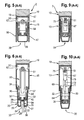
- Fig. 5 shows the cross section of the seal assembly according to Fig. 3 and
- Fig. 6 shows the Cross section of the seal arrangement according to Fig. 4 ,
- the present sealing arrangement comprises an elongated housing 15 (FIG. Fig. 5 ), which is associated with the lower edge 47 of the door leaf 2.
- This housing 15 has a substantially U-shaped cross-section, which includes the legs 16 and 17 and a web or bottom 18. It is usually formed from a profile rail, in particular made of aluminum. This bottom 18 connects the one ends of the housing legs 16 and 17 with each other.
- the housing 15 is bluntly connected via the outer surface of the bottom 18 of the same to the underside of the lower edge 47 of the door leaf 2, that the side walls 16 and 17 of the housing 15 project from the lower edge 47 of the door leaf 2 and thereby run vertically.
- the housing may also be arranged laterally on the door leaf or inserted into a groove of the door leaf. The fixation is done by means of known elements.
- the present sealing arrangement further comprises a sealing strip 30 (FIG. Fig. 6 ), which in the housing 15 extendable, that is, can be raised and lowered, is arranged.
- This sealing strip 30 has an elongated support 31 for the actual sealing member 35 of this sealing strip 30.
- the cross section of the carrier 31 is substantially U-shaped, so that this carrier 31 has two legs 32 and 33 and a bottom 34.
- the distance between the legs 32 and 33 of this support 31 is substantially smaller than the distance between the legs 16 and 17 of the housing 15.
- the support is usually also made of a rail, in particular made of aluminum.
- the sealing member 35 is made of a soft, in particular elastomeric, material and it is formed as a U-profile. This means that the sealing member 35 also has two legs 36 and 37 and a bottom 38. It is made in one piece. The distance and the course of the legs 36 and 37 of the sealing member 35 are chosen so that this sealing member 35 can be slipped over the carrier 31.
- At a distance from the bottom 38 of the sealing member 35 are narrow strips 39 and 40 from the inner surface of the legs 36 and 37 of the sealing member 35 and they extend in the longitudinal direction of this U-profile 35.
- These strips 39 and 40 lie in corresponding elongate recesses in the outside of the bottom 34 of the carrier 31. This ensures the position of the sealing profile 35 on the carrier 31, wherein the bottom 38 of the sealing member 30 is at a distance from the bottom 34 of the carrier 31.
- the distance between the inner surfaces of the U-legs 16 and 17 of the housing 15 is selected so that the sealing strip 30 together with the sealing member 25 can be retracted or raised into the housing 15.
- the present seal assembly also includes a device 50 which is housed in the housing 15 and which makes it possible to lower and lift the sealing strip 30.
- This actuating device or lowering device 50 comprises an actuating rod 51, which is located in the housing 15 and which extends parallel to the lower edge 47 of the door leaf 2 or parallel to the bottom 18 of the housing 15 and at a distance therefrom.
- This actuating rod 51 extends virtually over the entire width of the door leaf 2.
- There are bearing sleeves which protrude from the inside of the housing bottom 18 and are distributed along the housing bottom 18 at intervals from each other. In the simplest case, two such bearing sleeves 52 are provided. Through the bearing sleeves 52, the actuating rod 50 passes through and it is mounted longitudinally displaceable in these sleeves 52.
- the lowering device 50 further includes lowering devices 55, only one of which is shown in the drawings.
- lowering devices 55 For effective lowering of the sealing strip 30 requires at least two lowering devices 55. If the door 2 is very wide, then more than two lowering devices 55 are required.
- the lowering devices 55 are all made the same and they are at intervals from each other.
- the respective lowering device 55 comprises a connecting lever 56 which is pivotally connected at one end in the housing 15 of the arrangement and at the other end to the sealing strip 30.
- the lowering device 55 is associated with the actuating rod 51 so that the state of the lowering device is controllable by the actuating rod 51.
- the respective lowering device 55 also includes means 70 for accelerating the lowering of the sealing strip 30.
- These means 70 have a lever 71, which is associated with one end of the connecting lever 56.
- At the other end of this control lever 71 of the actuating rod 51 of the accelerator 55 is assigned so that the position of the connecting lever 56 is controlled by the control lever 71.
- At the respective end of the control lever 71 a bore 72 and 73 is executed. Through these holes go pins 76 and 77 through.
- a thickening 78 is carried out with a bore. Through this thickening 78, the first pin 76 passes, which at the same time also passes through the upper end portion of the control lever 71.
- the second pin 77 passes not only through the bore 73 in the bottom of the control lever 71 shown below but also through a corresponding hole in the connecting lever 56.
- This corresponding hole in the connecting lever 56 is within that half of the total length of the connecting lever 56, which starts at the operating rod 51 .
- the location of said connection points 76 and 77 of the control lever 71 to the actuating rod 51 and to the connecting lever 56 is selected so that the angle alpha between the control lever 71 and the lower edge 47 of the door leaf 2 is smaller when the door is open than when the door is closed.
- Fig. 3 to 6 show the present arrangement with a first embodiment of the connecting lever 56.
- the connecting lever 56 has an elongated body 57, which is designed as a substantially rigid elongated piece of material.
- This main body 57 has two differently shaped sections 58 and 59, which are arranged one behind the other.
- the first portion 58 of the main body 57 of the connecting lever 56 is rigid.
- the free end portion of this rigid portion 58 of the lever body 57 is pivotally mounted in the housing 15. Transversely through the housing 15 and in the vicinity of the bottom 18 of this housing 15 extends a pin 62, which passes through a corresponding eye 63 in this end portion of the connecting lever 56.
- the second portion 59 of the lever body 57 is resilient.
- the free end portion of this resilient portion 59 of the lever body 57 is pivotally connected to the sealing strip 30.
- a further pin 64 which extends through a Eye 65 at the free end of this second portion 59 of the connecting lever 56 is executed.
- the connecting lever 56 associated end portion of the control lever 71 is pivotally connected to this in the region of the transition between the two said portions of the lever body 57.
- the respective lowering device also includes a tension spring 80.
- One of the end portions of this tension spring 80 is connected in the region of the lower edge 47 of the door leaf 2, in particular on the actuating rod 51 or on the housing 15.
- the other end portion of the tension spring 80 is connected to the sealing strip 30.
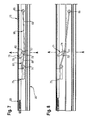
- Fig. 7 to 10 show the present arrangement with a second embodiment of the connecting lever 66.
- This connecting lever 66 has an elongated body 67, which is designed to be resilient.
- This main body 67 is made of a piece of resilient round steel and it is divided into two sections 68 and 69, which are arranged one behind the other.
- the free end portion of the first portion 68 of the lever body 67 is firmly in a block of material 75 which is fixed on the inside of the bottom 18 of the housing 15 and thus in the interior of this housing 15.
- the free end portion of the second portion 69 of the lever body 57 is pivotally connected to the sealing strip 30.
- this end portion 65 of the second portion 69 of the lever body 57 is located between the legs 32 and 33 of the carrier 31 with the U-section, which is practically the same length as the sealing member 35th
- the length of the first portion 68 of the lever body 67 is only about one third of the length of the second portion 69 of the lever body 67. Between the two sections 68 and 69 of the spring body 67 is formed into a first ring 60. The first portion 68 of the lever body 67 is formed between the material block 75 and the first ring 60 to a second ring 74. This second ring 74 is intended to increase the flexibility of the relatively short first section 68 of the lever main body 67.
- the connecting lever 66 associated end portion 73 of the control lever 71 is by means of a pin 77 to the ring 60 on the connecting lever 66th connected so that the control lever 71 in the region of the transition between the two said portions 68 and 69 of the lever body 67 is pivotally connected thereto.
- the other end portion of the control lever 71 is connected to the actuating rod 51 in the manner already described.
- the operating rod 51 which passes through the block of material 75 has a square, for example a rectangular cross-section to stabilize the position of the connecting lever 66 of a round steel in a vertical direction and against rotation.
- the lowering mechanism is triggered on one side.
- This end portion of the operating rod 51 is provided with an adjusting device 85.
- the adjusting device comprises a hollow nut 86, which has a hollow base body 87 with an internal thread and which is screwed onto a threaded end of the actuating rod 51.
- the protruding from the door leaf 2 end of this hollow body 87 is provided with a head 88.
- the diameter of this head 88 is greater than the diameter of the hollow body 87.
- This head 88 is located in the fold 12 on the door 2.
- control levers 71 move to the right with the actuating rod 51 when the head 88 pushes the actuating rod 51 to the right.
- the lower ends of the control lever 71 are hinged to the non-displaceable Veitatishebeln 56 and 66.
- both the connecting levers 56 and 66 and the sealing strip 30 carried by them are pressed downwards by the control levers 71, when the operating rod 51 moves to the right.
- a first important advantage of the present arrangement over the prior art is that the short control levers 71 accomplish a relatively large stroke of the sealing strip 30, although the travel of the actuating rod 51 is relatively short due to the small depth of the fold 6 on the door frame 1.
- a second important advantage of the present arrangement results from the length of the connecting levers 56 and 66. These levers 56 and 66 are made relatively long. The length of one of these levers 56 and 66 may be for example about seven times the distance between the bottom 18 of the housing 15 and the bottom 38 of the sealing member 35. The length of the lever 56 or 66 is the radius of a distance along which the pin 64 moves when the sealing strip 30 is moved from one of its end positions to the other end position in the manner set forth.
- the said distance of the pin 64 is practically rectilinear.
- the length of the connecting levers is a multiple of the height of the seal in the raised state.
- the two portion of the connecting lever are formed substantially longer than this height. The result of this is that the sealing strip 30, when moved from one of its end positions to the other end position, is practically only moved in the vertical direction and thus it carries out virtually no movement in its longitudinal direction.
- Fig. 6 also shows a second possible embodiment of the sealing strip 30.
- the bottom 38 of the sealing member 35 is provided with a recess 20 which has a U-shaped cross-section.
- This recess 20 extends over the entire length of the sealing member 35. Consequently, this recess 20 also has two flanks 21 and 23 and a bottom 23 connecting these flanks.
- the bottom 38 of the sealing member 35 has a recess 24 which extends over the entire length of the sealing member 35.
- the interior of the recess 20 and the chambers 26 and 27 between the flanks 26 and 36 and 27 and 37 represent air-filled cavities. It is known that successively arranged filled with air cavities provide excellent sound insulation, which can be exploited to advantage in the present case.
- the present arrangement can also be designed so that the head 88 of the actuating rod 51 is located on the side opposite the hinges 3 of the door leaf 2.
- the entire lowering movement of the sealing strip 30 could take place only in the last and very short phase of the closing movement of the door leaf 2.
- the bottom 38 of the sealing member 30 would perform during the very short phase of the closing movement of the door leaf 2 only a slight grinding movement on the room floor, which would result in only a slight wear of the bottom 38 of the sealing member 35.
Landscapes
- Engineering & Computer Science (AREA)
- Civil Engineering (AREA)
- Structural Engineering (AREA)
- Specific Sealing Or Ventilating Devices For Doors And Windows (AREA)
Applications Claiming Priority (1)
| Application Number | Priority Date | Filing Date | Title |
|---|---|---|---|
| CH1752008 | 2008-02-08 |
Publications (3)
| Publication Number | Publication Date |
|---|---|
| EP2088277A2 true EP2088277A2 (fr) | 2009-08-12 |
| EP2088277A3 EP2088277A3 (fr) | 2014-06-18 |
| EP2088277B1 EP2088277B1 (fr) | 2015-12-23 |
Family
ID=40640211
Family Applications (1)
| Application Number | Title | Priority Date | Filing Date |
|---|---|---|---|
| EP09405023.4A Active EP2088277B1 (fr) | 2008-02-08 | 2009-02-06 | Agencement d'étanchéité pour une porte sans seuil |
Country Status (1)
| Country | Link |
|---|---|
| EP (1) | EP2088277B1 (fr) |
Cited By (2)
| Publication number | Priority date | Publication date | Assignee | Title |
|---|---|---|---|---|
| AT518198A1 (de) * | 2016-01-18 | 2017-08-15 | Ing Degelsegger Walter | Dichtungsvorrichtung für den Randbereich eines bewegbaren Tür- oder Fensterflügels mit einer relativ zum Flügel bewegbaren Dichtleiste |
| US11274490B2 (en) * | 2017-01-05 | 2022-03-15 | Ad Solutions, Inc. | Top-hanging sliding door including bottom guide and seal |
Citations (2)
| Publication number | Priority date | Publication date | Assignee | Title |
|---|---|---|---|---|
| CH627228A5 (en) | 1978-02-06 | 1981-12-31 | Jaggi Matthias Planet | Automatic door seal for doors without thresholds |
| CH631779A5 (de) | 1980-08-15 | 1982-08-31 | Jaggi Matthias Planet | Dichtungsanordnung an einer schwellenlosen tuer. |
Family Cites Families (3)
| Publication number | Priority date | Publication date | Assignee | Title |
|---|---|---|---|---|
| US439942A (en) * | 1890-11-04 | Door attachment | ||
| CH534799A (de) * | 1971-02-26 | 1973-03-15 | Jaggi Matthias | Dichtungseinrichtung an einer schwellenlosen Türe |
| US4406088A (en) * | 1981-11-09 | 1983-09-27 | Berndt Jr Fred P | Door bottom sealing apparatus |
-
2009
- 2009-02-06 EP EP09405023.4A patent/EP2088277B1/fr active Active
Patent Citations (2)
| Publication number | Priority date | Publication date | Assignee | Title |
|---|---|---|---|---|
| CH627228A5 (en) | 1978-02-06 | 1981-12-31 | Jaggi Matthias Planet | Automatic door seal for doors without thresholds |
| CH631779A5 (de) | 1980-08-15 | 1982-08-31 | Jaggi Matthias Planet | Dichtungsanordnung an einer schwellenlosen tuer. |
Cited By (4)
| Publication number | Priority date | Publication date | Assignee | Title |
|---|---|---|---|---|
| AT518198A1 (de) * | 2016-01-18 | 2017-08-15 | Ing Degelsegger Walter | Dichtungsvorrichtung für den Randbereich eines bewegbaren Tür- oder Fensterflügels mit einer relativ zum Flügel bewegbaren Dichtleiste |
| AT518198B1 (de) * | 2016-01-18 | 2017-12-15 | Ing Degelsegger Walter | Dichtungsvorrichtung für den Randbereich eines bewegbaren Tür- oder Fensterflügels mit einer relativ zum Flügel bewegbaren Dichtleiste |
| US11274490B2 (en) * | 2017-01-05 | 2022-03-15 | Ad Solutions, Inc. | Top-hanging sliding door including bottom guide and seal |
| US12421790B2 (en) | 2017-01-05 | 2025-09-23 | Ad Solutions, Inc. | Top-hanging sliding door including bottom guide and seal |
Also Published As
| Publication number | Publication date |
|---|---|
| EP2088277B1 (fr) | 2015-12-23 |
| EP2088277A3 (fr) | 2014-06-18 |
Similar Documents
| Publication | Publication Date | Title |
|---|---|---|
| EP3165703B1 (fr) | Dispositif d'étanchéité abaissable | |
| EP0613797A2 (fr) | Porte de véhicule | |
| DE202011001104U1 (de) | Dichtungsvorrichtung mit einem Dichtungsprofil und einem Mechanismus zum Verschieben des Dichtungsprofils bei Betätigung des Mechanismus | |
| DE202009014785U1 (de) | Schiebetür | |
| EP0718456A1 (fr) | Système de fermeture pour fenêtre, porte etc. | |
| EP1936295A2 (fr) | Installation de fermeture d'une ouverture de local | |
| EP2050918B1 (fr) | Joint descendant doté d'une ouverture de passage | |
| EP3112577B1 (fr) | Joint abaissable | |
| EP2088277B1 (fr) | Agencement d'étanchéité pour une porte sans seuil | |
| EP3768931B1 (fr) | Unité d'étanchéité | |
| DE2451556A1 (de) | Feststellvorrichtung zur oeffnungsbegrenzung von kipp- und klappfluegeln, insbesondere kipp-schwenkfluegeln, an fenstern, tueren o.dgl. | |
| DE19806405A1 (de) | Einseitig auslösbare Türdichtungsvorrichtung | |
| EP4060158A1 (fr) | Paroi coulissante pourvue d'agencement d'étanchéité | |
| EP2267263B1 (fr) | Joint d'étanchéité pour porte | |
| DE10035378B4 (de) | Dichtungsanordnung für eine schwellenlose Türe | |
| DE102011000295A1 (de) | Vorrichtung zum automatischen Schließen oder Öffnen einer Schiebetür | |
| DE102018200582B3 (de) | Teleskopschiebetürsystem | |
| EP2682556B1 (fr) | Dispositif d'étanchéité pour une porte ou une fenêtre | |
| DE2160369C2 (de) | Begrenzungspuffer für die Aufwickelbewegung von Rolladenpanzern od. dgl. | |
| DE102012106191B4 (de) | Vorspannbauteil für eine Fenster- oder Türvorrichtung und Fenster- oder Türvorrichtung | |
| DE102004042853B3 (de) | Beschlag zur Lagerung mindestens einer Latte | |
| EP3768930B1 (fr) | Dispositif de joint d'étanchéité | |
| DE202004005162U1 (de) | Bodendichtung mit Federband | |
| EP3327228A1 (fr) | Dispositif de verrouillage destiné à verrouiller et à emmener au moins deux éléments en forme de plaque montés en coulissement le long d'une première direction de coulissement et d'une seconde direction de coulissement opposée et système de paroi comprenant au moins deux éléments en forme de plaque | |
| DE19932897A1 (de) | Mobile Trennwand |
Legal Events
| Date | Code | Title | Description |
|---|---|---|---|
| PUAI | Public reference made under article 153(3) epc to a published international application that has entered the european phase |
Free format text: ORIGINAL CODE: 0009012 |
|
| AK | Designated contracting states |
Kind code of ref document: A2 Designated state(s): AT BE BG CH CY CZ DE DK EE ES FI FR GB GR HR HU IE IS IT LI LT LU LV MC MK MT NL NO PL PT RO SE SI SK TR |
|
| AX | Request for extension of the european patent |
Extension state: AL BA RS |
|
| PUAL | Search report despatched |
Free format text: ORIGINAL CODE: 0009013 |
|
| AK | Designated contracting states |
Kind code of ref document: A3 Designated state(s): AT BE BG CH CY CZ DE DK EE ES FI FR GB GR HR HU IE IS IT LI LT LU LV MC MK MT NL NO PL PT RO SE SI SK TR |
|
| AX | Request for extension of the european patent |
Extension state: AL BA RS |
|
| RIC1 | Information provided on ipc code assigned before grant |
Ipc: E06B 7/215 20060101AFI20140515BHEP |
|
| RAP1 | Party data changed (applicant data changed or rights of an application transferred) |
Owner name: PLANET GDZ AG |
|
| REG | Reference to a national code |
Ref country code: DE Ref legal event code: R079 Ref document number: 502009011951 Country of ref document: DE Free format text: PREVIOUS MAIN CLASS: E06B0007215000 Ipc: E06B0007230000 |
|
| 17P | Request for examination filed |
Effective date: 20141211 |
|
| RBV | Designated contracting states (corrected) |
Designated state(s): AT BE BG CH CY CZ DE DK EE ES FI FR GB GR HR HU IE IS IT LI LT LU LV MC MK MT NL NO PL PT RO SE SI SK TR |
|
| GRAP | Despatch of communication of intention to grant a patent |
Free format text: ORIGINAL CODE: EPIDOSNIGR1 |
|
| RIC1 | Information provided on ipc code assigned before grant |
Ipc: E06B 7/215 20060101ALI20150115BHEP Ipc: E06B 7/23 20060101AFI20150115BHEP |
|
| AKX | Designation fees paid |
Designated state(s): AT BE BG CH CY CZ DE DK EE ES FI FR GB GR HR HU IE IS IT LI LT LU LV MC MK MT NL NO PL PT RO SE SI SK TR |
|
| AXX | Extension fees paid |
Extension state: BA Extension state: AL Extension state: RS |
|
| INTG | Intention to grant announced |
Effective date: 20150205 |
|
| GRAP | Despatch of communication of intention to grant a patent |
Free format text: ORIGINAL CODE: EPIDOSNIGR1 |
|
| INTG | Intention to grant announced |
Effective date: 20150629 |
|
| GRAS | Grant fee paid |
Free format text: ORIGINAL CODE: EPIDOSNIGR3 |
|
| GRAA | (expected) grant |
Free format text: ORIGINAL CODE: 0009210 |
|
| AK | Designated contracting states |
Kind code of ref document: B1 Designated state(s): AT BE BG CH CY CZ DE DK EE ES FI FR GB GR HR HU IE IS IT LI LT LU LV MC MK MT NL NO PL PT RO SE SI SK TR |
|
| REG | Reference to a national code |
Ref country code: GB Ref legal event code: FG4D Free format text: NOT ENGLISH |
|
| REG | Reference to a national code |
Ref country code: CH Ref legal event code: EP |
|
| REG | Reference to a national code |
Ref country code: IE Ref legal event code: FG4D Free format text: LANGUAGE OF EP DOCUMENT: GERMAN |
|
| REG | Reference to a national code |
Ref country code: AT Ref legal event code: REF Ref document number: 766660 Country of ref document: AT Kind code of ref document: T Effective date: 20160115 Ref country code: CH Ref legal event code: NV Representative=s name: ISLER AND PEDRAZZINI AG, CH |
|
| REG | Reference to a national code |
Ref country code: FR Ref legal event code: PLFP Year of fee payment: 8 |
|
| REG | Reference to a national code |
Ref country code: DE Ref legal event code: R096 Ref document number: 502009011951 Country of ref document: DE |
|
| REG | Reference to a national code |
Ref country code: NL Ref legal event code: FP |
|
| REG | Reference to a national code |
Ref country code: LT Ref legal event code: MG4D |
|
| PG25 | Lapsed in a contracting state [announced via postgrant information from national office to epo] |
Ref country code: HR Free format text: LAPSE BECAUSE OF FAILURE TO SUBMIT A TRANSLATION OF THE DESCRIPTION OR TO PAY THE FEE WITHIN THE PRESCRIBED TIME-LIMIT Effective date: 20151223 Ref country code: LT Free format text: LAPSE BECAUSE OF FAILURE TO SUBMIT A TRANSLATION OF THE DESCRIPTION OR TO PAY THE FEE WITHIN THE PRESCRIBED TIME-LIMIT Effective date: 20151223 Ref country code: NO Free format text: LAPSE BECAUSE OF FAILURE TO SUBMIT A TRANSLATION OF THE DESCRIPTION OR TO PAY THE FEE WITHIN THE PRESCRIBED TIME-LIMIT Effective date: 20160323 |
|
| PG25 | Lapsed in a contracting state [announced via postgrant information from national office to epo] |
Ref country code: GR Free format text: LAPSE BECAUSE OF FAILURE TO SUBMIT A TRANSLATION OF THE DESCRIPTION OR TO PAY THE FEE WITHIN THE PRESCRIBED TIME-LIMIT Effective date: 20160324 Ref country code: FI Free format text: LAPSE BECAUSE OF FAILURE TO SUBMIT A TRANSLATION OF THE DESCRIPTION OR TO PAY THE FEE WITHIN THE PRESCRIBED TIME-LIMIT Effective date: 20151223 Ref country code: BE Free format text: LAPSE BECAUSE OF NON-PAYMENT OF DUE FEES Effective date: 20160229 Ref country code: LV Free format text: LAPSE BECAUSE OF FAILURE TO SUBMIT A TRANSLATION OF THE DESCRIPTION OR TO PAY THE FEE WITHIN THE PRESCRIBED TIME-LIMIT Effective date: 20151223 Ref country code: SE Free format text: LAPSE BECAUSE OF FAILURE TO SUBMIT A TRANSLATION OF THE DESCRIPTION OR TO PAY THE FEE WITHIN THE PRESCRIBED TIME-LIMIT Effective date: 20151223 |
|
| PG25 | Lapsed in a contracting state [announced via postgrant information from national office to epo] |
Ref country code: ES Free format text: LAPSE BECAUSE OF FAILURE TO SUBMIT A TRANSLATION OF THE DESCRIPTION OR TO PAY THE FEE WITHIN THE PRESCRIBED TIME-LIMIT Effective date: 20151223 Ref country code: CZ Free format text: LAPSE BECAUSE OF FAILURE TO SUBMIT A TRANSLATION OF THE DESCRIPTION OR TO PAY THE FEE WITHIN THE PRESCRIBED TIME-LIMIT Effective date: 20151223 |
|
| PG25 | Lapsed in a contracting state [announced via postgrant information from national office to epo] |
Ref country code: SK Free format text: LAPSE BECAUSE OF FAILURE TO SUBMIT A TRANSLATION OF THE DESCRIPTION OR TO PAY THE FEE WITHIN THE PRESCRIBED TIME-LIMIT Effective date: 20151223 Ref country code: IS Free format text: LAPSE BECAUSE OF FAILURE TO SUBMIT A TRANSLATION OF THE DESCRIPTION OR TO PAY THE FEE WITHIN THE PRESCRIBED TIME-LIMIT Effective date: 20160423 Ref country code: PL Free format text: LAPSE BECAUSE OF FAILURE TO SUBMIT A TRANSLATION OF THE DESCRIPTION OR TO PAY THE FEE WITHIN THE PRESCRIBED TIME-LIMIT Effective date: 20151223 Ref country code: RO Free format text: LAPSE BECAUSE OF FAILURE TO SUBMIT A TRANSLATION OF THE DESCRIPTION OR TO PAY THE FEE WITHIN THE PRESCRIBED TIME-LIMIT Effective date: 20151223 Ref country code: EE Free format text: LAPSE BECAUSE OF FAILURE TO SUBMIT A TRANSLATION OF THE DESCRIPTION OR TO PAY THE FEE WITHIN THE PRESCRIBED TIME-LIMIT Effective date: 20151223 Ref country code: PT Free format text: LAPSE BECAUSE OF FAILURE TO SUBMIT A TRANSLATION OF THE DESCRIPTION OR TO PAY THE FEE WITHIN THE PRESCRIBED TIME-LIMIT Effective date: 20160426 |
|
| REG | Reference to a national code |
Ref country code: DE Ref legal event code: R097 Ref document number: 502009011951 Country of ref document: DE |
|
| PG25 | Lapsed in a contracting state [announced via postgrant information from national office to epo] |
Ref country code: MC Free format text: LAPSE BECAUSE OF FAILURE TO SUBMIT A TRANSLATION OF THE DESCRIPTION OR TO PAY THE FEE WITHIN THE PRESCRIBED TIME-LIMIT Effective date: 20151223 Ref country code: LU Free format text: LAPSE BECAUSE OF FAILURE TO SUBMIT A TRANSLATION OF THE DESCRIPTION OR TO PAY THE FEE WITHIN THE PRESCRIBED TIME-LIMIT Effective date: 20160206 |
|
| PLBE | No opposition filed within time limit |
Free format text: ORIGINAL CODE: 0009261 |
|
| STAA | Information on the status of an ep patent application or granted ep patent |
Free format text: STATUS: NO OPPOSITION FILED WITHIN TIME LIMIT |
|
| PG25 | Lapsed in a contracting state [announced via postgrant information from national office to epo] |
Ref country code: DK Free format text: LAPSE BECAUSE OF FAILURE TO SUBMIT A TRANSLATION OF THE DESCRIPTION OR TO PAY THE FEE WITHIN THE PRESCRIBED TIME-LIMIT Effective date: 20151223 |
|
| 26N | No opposition filed |
Effective date: 20160926 |
|
| REG | Reference to a national code |
Ref country code: IE Ref legal event code: MM4A |
|
| PG25 | Lapsed in a contracting state [announced via postgrant information from national office to epo] |
Ref country code: IE Free format text: LAPSE BECAUSE OF NON-PAYMENT OF DUE FEES Effective date: 20160206 |
|
| REG | Reference to a national code |
Ref country code: FR Ref legal event code: PLFP Year of fee payment: 9 |
|
| PG25 | Lapsed in a contracting state [announced via postgrant information from national office to epo] |
Ref country code: SI Free format text: LAPSE BECAUSE OF FAILURE TO SUBMIT A TRANSLATION OF THE DESCRIPTION OR TO PAY THE FEE WITHIN THE PRESCRIBED TIME-LIMIT Effective date: 20151223 |
|
| PG25 | Lapsed in a contracting state [announced via postgrant information from national office to epo] |
Ref country code: MT Free format text: LAPSE BECAUSE OF FAILURE TO SUBMIT A TRANSLATION OF THE DESCRIPTION OR TO PAY THE FEE WITHIN THE PRESCRIBED TIME-LIMIT Effective date: 20151223 |
|
| REG | Reference to a national code |
Ref country code: FR Ref legal event code: PLFP Year of fee payment: 10 |
|
| PG25 | Lapsed in a contracting state [announced via postgrant information from national office to epo] |
Ref country code: HU Free format text: LAPSE BECAUSE OF FAILURE TO SUBMIT A TRANSLATION OF THE DESCRIPTION OR TO PAY THE FEE WITHIN THE PRESCRIBED TIME-LIMIT; INVALID AB INITIO Effective date: 20090206 Ref country code: CY Free format text: LAPSE BECAUSE OF FAILURE TO SUBMIT A TRANSLATION OF THE DESCRIPTION OR TO PAY THE FEE WITHIN THE PRESCRIBED TIME-LIMIT Effective date: 20151223 |
|
| PG25 | Lapsed in a contracting state [announced via postgrant information from national office to epo] |
Ref country code: TR Free format text: LAPSE BECAUSE OF FAILURE TO SUBMIT A TRANSLATION OF THE DESCRIPTION OR TO PAY THE FEE WITHIN THE PRESCRIBED TIME-LIMIT Effective date: 20151223 Ref country code: MK Free format text: LAPSE BECAUSE OF FAILURE TO SUBMIT A TRANSLATION OF THE DESCRIPTION OR TO PAY THE FEE WITHIN THE PRESCRIBED TIME-LIMIT Effective date: 20151223 |
|
| PG25 | Lapsed in a contracting state [announced via postgrant information from national office to epo] |
Ref country code: BG Free format text: LAPSE BECAUSE OF FAILURE TO SUBMIT A TRANSLATION OF THE DESCRIPTION OR TO PAY THE FEE WITHIN THE PRESCRIBED TIME-LIMIT Effective date: 20151223 |
|
| PGFP | Annual fee paid to national office [announced via postgrant information from national office to epo] |
Ref country code: NL Payment date: 20210212 Year of fee payment: 13 Ref country code: FR Payment date: 20210126 Year of fee payment: 13 |
|
| PGFP | Annual fee paid to national office [announced via postgrant information from national office to epo] |
Ref country code: AT Payment date: 20210125 Year of fee payment: 13 Ref country code: GB Payment date: 20210127 Year of fee payment: 13 |
|
| REG | Reference to a national code |
Ref country code: NL Ref legal event code: MM Effective date: 20220301 |
|
| REG | Reference to a national code |
Ref country code: AT Ref legal event code: MM01 Ref document number: 766660 Country of ref document: AT Kind code of ref document: T Effective date: 20220206 |
|
| GBPC | Gb: european patent ceased through non-payment of renewal fee |
Effective date: 20220206 |
|
| PG25 | Lapsed in a contracting state [announced via postgrant information from national office to epo] |
Ref country code: AT Free format text: LAPSE BECAUSE OF NON-PAYMENT OF DUE FEES Effective date: 20220206 |
|
| PG25 | Lapsed in a contracting state [announced via postgrant information from national office to epo] |
Ref country code: NL Free format text: LAPSE BECAUSE OF NON-PAYMENT OF DUE FEES Effective date: 20220301 Ref country code: FR Free format text: LAPSE BECAUSE OF NON-PAYMENT OF DUE FEES Effective date: 20220228 |
|
| PG25 | Lapsed in a contracting state [announced via postgrant information from national office to epo] |
Ref country code: GB Free format text: LAPSE BECAUSE OF NON-PAYMENT OF DUE FEES Effective date: 20220206 |
|
| PGFP | Annual fee paid to national office [announced via postgrant information from national office to epo] |
Ref country code: IT Payment date: 20240111 Year of fee payment: 16 |
|
| PGFP | Annual fee paid to national office [announced via postgrant information from national office to epo] |
Ref country code: DE Payment date: 20250108 Year of fee payment: 17 |
|
| PGFP | Annual fee paid to national office [announced via postgrant information from national office to epo] |
Ref country code: CH Payment date: 20250301 Year of fee payment: 17 |
|
| PG25 | Lapsed in a contracting state [announced via postgrant information from national office to epo] |
Ref country code: IT Free format text: LAPSE BECAUSE OF NON-PAYMENT OF DUE FEES Effective date: 20250206 |