EP2088288A2 - Gasturbinensystem - Google Patents
Gasturbinensystem Download PDFInfo
- Publication number
- EP2088288A2 EP2088288A2 EP09151741A EP09151741A EP2088288A2 EP 2088288 A2 EP2088288 A2 EP 2088288A2 EP 09151741 A EP09151741 A EP 09151741A EP 09151741 A EP09151741 A EP 09151741A EP 2088288 A2 EP2088288 A2 EP 2088288A2
- Authority
- EP
- European Patent Office
- Prior art keywords
- fuel
- flow
- gas turbine
- turbine engine
- engine system
- Prior art date
- Legal status (The legal status is an assumption and is not a legal conclusion. Google has not performed a legal analysis and makes no representation as to the accuracy of the status listed.)
- Withdrawn
Links
- 239000000446 fuel Substances 0.000 claims abstract description 292
- 239000000203 mixture Substances 0.000 claims abstract description 107
- 230000000704 physical effect Effects 0.000 claims abstract description 52
- 238000002347 injection Methods 0.000 claims abstract description 17
- 239000007924 injection Substances 0.000 claims abstract description 17
- 238000012937 correction Methods 0.000 claims abstract description 16
- XLYOFNOQVPJJNP-UHFFFAOYSA-N water Chemical compound O XLYOFNOQVPJJNP-UHFFFAOYSA-N 0.000 claims description 69
- 238000010438 heat treatment Methods 0.000 claims description 21
- 230000008859 change Effects 0.000 claims description 11
- 230000004044 response Effects 0.000 claims description 4
- 239000007789 gas Substances 0.000 description 127
- VNWKTOKETHGBQD-UHFFFAOYSA-N methane Chemical compound C VNWKTOKETHGBQD-UHFFFAOYSA-N 0.000 description 80
- 229910001868 water Inorganic materials 0.000 description 65
- 238000002485 combustion reaction Methods 0.000 description 27
- 238000000034 method Methods 0.000 description 27
- 239000003345 natural gas Substances 0.000 description 26
- 238000013461 design Methods 0.000 description 18
- 239000003570 air Substances 0.000 description 8
- 239000004909 Moisturizer Substances 0.000 description 6
- 239000002737 fuel gas Substances 0.000 description 6
- 230000005484 gravity Effects 0.000 description 6
- 230000001333 moisturizer Effects 0.000 description 6
- 229910009112 xH2O Inorganic materials 0.000 description 5
- 238000004364 calculation method Methods 0.000 description 4
- 239000000567 combustion gas Substances 0.000 description 4
- 238000004891 communication Methods 0.000 description 4
- 230000001276 controlling effect Effects 0.000 description 4
- 238000010586 diagram Methods 0.000 description 4
- 238000011144 upstream manufacturing Methods 0.000 description 4
- 238000006243 chemical reaction Methods 0.000 description 3
- 239000000470 constituent Substances 0.000 description 3
- 238000010304 firing Methods 0.000 description 3
- 230000001932 seasonal effect Effects 0.000 description 3
- 238000012546 transfer Methods 0.000 description 3
- 239000012080 ambient air Substances 0.000 description 2
- 239000003085 diluting agent Substances 0.000 description 2
- 239000012530 fluid Substances 0.000 description 2
- 238000004519 manufacturing process Methods 0.000 description 2
- 238000005259 measurement Methods 0.000 description 2
- 230000003068 static effect Effects 0.000 description 2
- 230000002411 adverse Effects 0.000 description 1
- 230000003416 augmentation Effects 0.000 description 1
- 238000009529 body temperature measurement Methods 0.000 description 1
- -1 but not limited to Substances 0.000 description 1
- 239000003795 chemical substances by application Substances 0.000 description 1
- 238000009833 condensation Methods 0.000 description 1
- 230000005494 condensation Effects 0.000 description 1
- 239000002283 diesel fuel Substances 0.000 description 1
- 239000000428 dust Substances 0.000 description 1
- 230000000694 effects Effects 0.000 description 1
- 239000000284 extract Substances 0.000 description 1
- 230000002349 favourable effect Effects 0.000 description 1
- 239000003502 gasoline Substances 0.000 description 1
- 230000003116 impacting effect Effects 0.000 description 1
- 239000003350 kerosene Substances 0.000 description 1
- 239000003949 liquefied natural gas Substances 0.000 description 1
- 239000000463 material Substances 0.000 description 1
- 238000012986 modification Methods 0.000 description 1
- 230000004048 modification Effects 0.000 description 1
- 238000011084 recovery Methods 0.000 description 1
- 230000001105 regulatory effect Effects 0.000 description 1
- 229920006395 saturated elastomer Polymers 0.000 description 1
- 230000007704 transition Effects 0.000 description 1
Images


Classifications
-
- H—ELECTRICITY
- H04—ELECTRIC COMMUNICATION TECHNIQUE
- H04B—TRANSMISSION
- H04B17/00—Monitoring; Testing
- H04B17/30—Monitoring; Testing of propagation channels
- H04B17/309—Measuring or estimating channel quality parameters
- H04B17/345—Interference values
-
- F—MECHANICAL ENGINEERING; LIGHTING; HEATING; WEAPONS; BLASTING
- F02—COMBUSTION ENGINES; HOT-GAS OR COMBUSTION-PRODUCT ENGINE PLANTS
- F02C—GAS-TURBINE PLANTS; AIR INTAKES FOR JET-PROPULSION PLANTS; CONTROLLING FUEL SUPPLY IN AIR-BREATHING JET-PROPULSION PLANTS
- F02C7/00—Features, components parts, details or accessories, not provided for in, or of interest apart form groups F02C1/00 - F02C6/00; Air intakes for jet-propulsion plants
- F02C7/22—Fuel supply systems
- F02C7/222—Fuel flow conduits, e.g. manifolds
-
- F—MECHANICAL ENGINEERING; LIGHTING; HEATING; WEAPONS; BLASTING
- F02—COMBUSTION ENGINES; HOT-GAS OR COMBUSTION-PRODUCT ENGINE PLANTS
- F02C—GAS-TURBINE PLANTS; AIR INTAKES FOR JET-PROPULSION PLANTS; CONTROLLING FUEL SUPPLY IN AIR-BREATHING JET-PROPULSION PLANTS
- F02C7/00—Features, components parts, details or accessories, not provided for in, or of interest apart form groups F02C1/00 - F02C6/00; Air intakes for jet-propulsion plants
- F02C7/22—Fuel supply systems
- F02C7/232—Fuel valves; Draining valves or systems
-
- F—MECHANICAL ENGINEERING; LIGHTING; HEATING; WEAPONS; BLASTING
- F02—COMBUSTION ENGINES; HOT-GAS OR COMBUSTION-PRODUCT ENGINE PLANTS
- F02C—GAS-TURBINE PLANTS; AIR INTAKES FOR JET-PROPULSION PLANTS; CONTROLLING FUEL SUPPLY IN AIR-BREATHING JET-PROPULSION PLANTS
- F02C9/00—Controlling gas-turbine plants; Controlling fuel supply in air- breathing jet-propulsion plants
- F02C9/26—Control of fuel supply
-
- F—MECHANICAL ENGINEERING; LIGHTING; HEATING; WEAPONS; BLASTING
- F02—COMBUSTION ENGINES; HOT-GAS OR COMBUSTION-PRODUCT ENGINE PLANTS
- F02C—GAS-TURBINE PLANTS; AIR INTAKES FOR JET-PROPULSION PLANTS; CONTROLLING FUEL SUPPLY IN AIR-BREATHING JET-PROPULSION PLANTS
- F02C9/00—Controlling gas-turbine plants; Controlling fuel supply in air- breathing jet-propulsion plants
- F02C9/26—Control of fuel supply
- F02C9/28—Regulating systems responsive to plant or ambient parameters, e.g. temperature, pressure, rotor speed
-
- F—MECHANICAL ENGINEERING; LIGHTING; HEATING; WEAPONS; BLASTING
- F05—INDEXING SCHEMES RELATING TO ENGINES OR PUMPS IN VARIOUS SUBCLASSES OF CLASSES F01-F04
- F05D—INDEXING SCHEME FOR ASPECTS RELATING TO NON-POSITIVE-DISPLACEMENT MACHINES OR ENGINES, GAS-TURBINES OR JET-PROPULSION PLANTS
- F05D2220/00—Application
- F05D2220/70—Application in combination with
- F05D2220/76—Application in combination with an electrical generator
-
- F—MECHANICAL ENGINEERING; LIGHTING; HEATING; WEAPONS; BLASTING
- F05—INDEXING SCHEMES RELATING TO ENGINES OR PUMPS IN VARIOUS SUBCLASSES OF CLASSES F01-F04
- F05D—INDEXING SCHEME FOR ASPECTS RELATING TO NON-POSITIVE-DISPLACEMENT MACHINES OR ENGINES, GAS-TURBINES OR JET-PROPULSION PLANTS
- F05D2260/00—Function
- F05D2260/81—Modelling or simulation
-
- F—MECHANICAL ENGINEERING; LIGHTING; HEATING; WEAPONS; BLASTING
- F05—INDEXING SCHEMES RELATING TO ENGINES OR PUMPS IN VARIOUS SUBCLASSES OF CLASSES F01-F04
- F05D—INDEXING SCHEME FOR ASPECTS RELATING TO NON-POSITIVE-DISPLACEMENT MACHINES OR ENGINES, GAS-TURBINES OR JET-PROPULSION PLANTS
- F05D2270/00—Control
- F05D2270/30—Control parameters, e.g. input parameters
- F05D2270/31—Fuel schedule for stage combustors
-
- Y—GENERAL TAGGING OF NEW TECHNOLOGICAL DEVELOPMENTS; GENERAL TAGGING OF CROSS-SECTIONAL TECHNOLOGIES SPANNING OVER SEVERAL SECTIONS OF THE IPC; TECHNICAL SUBJECTS COVERED BY FORMER USPC CROSS-REFERENCE ART COLLECTIONS [XRACs] AND DIGESTS
- Y02—TECHNOLOGIES OR APPLICATIONS FOR MITIGATION OR ADAPTATION AGAINST CLIMATE CHANGE
- Y02E—REDUCTION OF GREENHOUSE GAS [GHG] EMISSIONS, RELATED TO ENERGY GENERATION, TRANSMISSION OR DISTRIBUTION
- Y02E20/00—Combustion technologies with mitigation potential
- Y02E20/16—Combined cycle power plant [CCPP], or combined cycle gas turbine [CCGT]
Definitions
- This invention relates generally to gas turbine engines, and more particularly, to methods and apparatus for controlling the operation of gas turbine engines.
- Gas turbine engines typically include a compressor section, a combustor section, and at least one turbine section.
- the compressor compresses air, which is mixed with fuel and channeled to the combustor.
- the mixture is then ignited generating hot combustion gases.
- the combustion gases are channeled to the turbine, which extracts energy from the combustion gases for powering the compressor, as well as producing useful work to power a load, such as an electrical generator, or to propel an aircraft in flight.
- Gas turbine engines operate in many different operating conditions, and combustor performance facilitates engine operation over a wide range of engine operating conditions. Controlling combustor performance may be used to improve overall gas turbine engine operations. More specifically, permitting a larger variation in gas fuel composition, for example, heating value and specific gravity, while maintaining NO x emissions and combustion dynamics levels within predetermined limits.
- Gas turbines equipped with Dry Low NO x (DLN) combustion systems typically utilize fuel delivery systems that include multi-nozzle, premixed combustors.
- DLN combustor designs utilize lean premixed combustion to achieve low NO x emissions without using diluents such as water or steam.
- Lean premixed combustion involves premixing the fuel and air upstream of the combustor flame zone and operation near the lean flammability limit of the fuel to keep peak flame temperatures and NO x production low.
- DLN combustors typically have multiple fuel nozzles in each combustion chamber that are fueled individually or in sub-groups.
- the gas turbine fuel system has a separately controlled delivery circuit to supply each group of nozzles in each chamber.
- the control system varies the fuel flow (fuel split) to each circuit over the turbine operating range to maintain flame stability, low emissions, and acceptable combustor life.
- Fuel flow to each nozzle sub-group is controlled via a gas control valve (GCV).
- GCV gas control valve
- the fuel split acts to divide the total fuel command (Fuel Stroke Reference) amongst the active GCV's, and the resulting percentage GCV fuel flow command is converted to a valve position to achieve the desired fuel flow to the nozzle sub-group.
- valve flow capacity coefficient Cg
- the valve capacity coefficient is translated to valve position using the known valve flow characteristic. This allows the use of multiple valves with varying capacities.
- the flow gain also called GCV flow scalar, is based on the maximum required Cg during the maximum fuel flow operating condition.
- the inputs used to calculate the flow gain are dependant on fuel constituents and the application of this flow conversion technique is limited to applications with fairly constant fuel properties.
- Traditional methods using the flow gain assume the fuel properties are constant throughout the loading range, which is not always the case. Therefore, without correcting for changes in fuel properties the flow gain will not properly linearize the flow command across the loading range. This can lead to an undesirable droop non-linearity and can cause load transients when fuel properties change significantly, for example during fuel transfers or following large changes in fuel temperature.
- a gas turbine engine in one embodiment according to the present invention, includes an electrical generator configured to provide electrical energy to a load, a gas turbine engine including at least one combustor including a plurality of fuel injection points configured to receive a flow of fuel from a plurality of corresponding flow control devices, and a fuel control system.
- the fuel control system includes a plurality of sensors positioned about the gas turbine engine system and configured to measure at least one parameter associated with the sensor and a processor.
- the processor is programmed to receive a signal from at least one of the plurality of sensors indicative of a composition of the fuel, using a flow model and the at least one signal, determine the physical properties of a fuel at an inlet to the flow control devices, determine a corresponding correction to a gas fuel flow gain using the determined physical properties, and automatically control fuel delivery as well as fuel split between the fuel injection points on the combustor using the adjusted flow gain to facilitate permitting a relatively large variation in the fuel composition for use in the gas turbine engine.
- a method of operating a gas turbine engine includes receiving a signal indicative of a composition of the fuel, determining physical properties of the fuel at an inlet to at least one flow control device using a flow model and the fuel composition signal, determining a corresponding correction to a gas fuel flow gain using the determined physical properties, and automatically control fuel delivery as well as fuel split between the fuel injection points on the combustor using the adjusted flow gain.
- a fuel control system in yet another embodiment, includes a fuel inlet configured to admit a flow of fuel into the fuel control system, a fuel moisturizer coupled in flow communication with the fuel inlet through a first pipe component, at least one flow control device configured to modulate flow to one or more injection points in a fuel control system load, at least one flow control device coupled in flow communication with a fuel moisturizer through a second pipe component, a plurality of sensors positioned about the fuel control system and configured to measure at least one parameter associated with the sensor, and a processor.
- the processor is programmed to receive a signal from at least one of the plurality of sensors indicative of a composition of the fuel, using a flow model and the at least one signal, determine the physical properties of a fuel at an inlet to the flow control devices, and determine a corresponding correction to a gas fuel flow gain using the determined physical properties and automatically control fuel delivery as well as fuel split between the fuel injection points on the combustor using the adjusted flow gain to facilitate permitting a relatively large variation in the fuel composition for use in the gas turbine engine.
- Figure 1 is a schematic diagram of a gas turbine engine system 10 including a compressor 12, a combustor 14, a turbine 16 drivingly coupled to compressor 12, and a control system 18.
- An inlet duct 20 channels ambient air to the compressor. In one embodiment, injected water and/or other humidifying agent is also channeled to the compressor through inlet duct 20.
- Inlet duct 20 may have ducts, filters, screens and sound absorbing devices that contribute to a pressure loss of ambient air flowing through inlet duct 20 into one or more inlet guide vanes 21 of compressor 12.
- An exhaust duct 22 channels combustion gases from an outlet of turbine 16 through, for example, emission control and sound absorbing devices. Exhaust duct 22 may include sound adsorbing materials and emission control devices that apply a backpressure to turbine 16.
- the amount of inlet pressure loss and back pressure may vary over time due to the addition of components to ducts 20, 22, and to dust and dirt clogging the inlet and exhaust ducts.
- Turbine 16 may drive a generator 24 that produces electrical power.
- the inlet loss to compressor 12 and turbine exhaust pressure loss tend to be a function of corrected flow through the gas turbine. Further, the amount of inlet loss and turbine back-pressure may vary with the flow rate through the gas turbine.
- the operation of the gas turbine engine system 10 may be monitored by several sensors 26 detecting various conditions of turbine 16, generator 24 and ambient environment.
- temperature sensors 26 may monitor ambient temperature surrounding gas turbine engine system 10, compressor discharge temperature, turbine exhaust gas temperature, and other temperature measurements of the gas stream through the gas turbine engine.
- Pressure sensors 26 may monitor ambient pressure, and static and dynamic pressure levels at the compressor inlet and outlet, turbine exhaust, at other locations in the gas stream through the gas turbine.
- Humidity sensors 26, such as wet and dry bulb thermometers measure ambient humidity in the inlet duct of the compressor.
- Sensors 26 may also comprise flow sensors, speed sensors, flame detector sensors, valve position sensors, guide vane angle sensors and other sensors that sense various parameters relative to the operation of gas turbine engine system 10.
- “parameters” refer to physical properties whose values can be used to define the operating conditions of gas turbine engine system 10, such as temperatures, pressures, and gas flows at defined locations.
- a fuel control system 28 regulates the fuel flowing from a fuel supply to combustor 14, and the split between the fuel flowing into various fuel nozzles located about the combustion chamber. Fuel control system 28 may also select the type of fuel for the combustor. The fuel control system 28 may be a separate unit or may be a component of control system 18. Fuel control system 28 may also generate and implement fuel split commands that determine the portion of fuel flowing to fuel nozzle subgroups.
- Control system 18 may be a computer system having a processor(s) that executes programs to control the operation of the gas turbine using sensor inputs and instructions from human operators.
- the programs executed by the controller 18 may include scheduling algorithms for regulating fuel flow to combustor 14.
- the commands generated by the controller cause actuators on the gas turbine to, for example, adjust valves (actuator 32) between the fuel supply and combustors that regulate the flow, fuel splits and type of fuel flowing to the combustors; adjust inlet guide vanes 21 (actuator 30) on the compressor, and activate other control settings on the gas turbine.
- Control system 18 regulates the gas turbine based, in part, on algorithms stored in computer memory of the controller. These algorithms enable control system 18 to maintain the NO x and CO emissions in the turbine exhaust to within certain predefined emission limits, and to maintain the combustor firing temperature to within predefined temperature limits.
- the algorithms have inputs for parameter variables for current compressor pressure ratio, ambient specific humidity, inlet pressure loss and turbine exhaust back pressure. Because of the parameters in inputs used by the algorithms, control system 18 accommodates seasonal variations in ambient temperature and humidity, and changes in the inlet pressure loss through the inlet 20 of the gas turbine and in the exhaust back pressure at the exhaust duct 22.
- Input parameters for ambient conditions, and inlet pressure loss and exhaust back pressure enable NO x , CO and turbine firing algorithms executing in control system 18 to automatically compensate for seasonal variations in gas turbine operation and changes in inlet loss and in back pressure. Accordingly, the need is reduced for an operator to manually adjust a gas turbine to account for seasonal variations in ambient conditions and for changes in the inlet pressure loss or turbine exhaust back pressure.
- the combustor 14 may be a DLN combustion system.
- Control system 18 may be programmed and modified to control the DLN combustion system and for determining fuel splits.
- control system 18 accommodate variations in ambient conditions (temperature, humidity, inlet pressure loss, and exhaust back pressure) that affect NO x , combustor dynamics, and firing temperature limits at part-load gas turbine operating conditions.
- Control system 18 simultaneously schedules exhaust temperature and combustor fuel splits.
- Control system 18 applies algorithms for scheduling the gas turbine, such as setting desired turbine exhaust temperatures and combustor fuel splits, so as to satisfy performance objectives while complying with operability boundaries of the gas turbine.
- Control system 18 simultaneously determines level combustor temperature rise and NO x during part-load operation in order to increase the operating margin to the combustion dynamics boundary and thereby improve operability, reliability, and availability of the gas turbine.
- the combustor fuel splits are scheduled by control system 18 to maintain the desired combustion mode while observing other operability boundaries, such as combustion dynamics.
- the cycle match point and the combustor fuel splits influence the resultant NO x emissions.
- Simultaneously leveling NO x and combustor temperature rise during part-load operation minimizes the level of combustion dynamics and expands the operational envelope of the gas turbine without adversely impacting emissions compliance or parts life.
- Combustors 14 include a plurality of fuel control valves supplying two or more injector groups in each combustor to allow modulation of modes of operation, emissions and combustion dynamics levels versus machine load. By modulating fuel splits among the several fuel gas control valves, emissions and dynamics are optimized over the machine load range. Fuel split modulation depends on a calculated reference parameter, called combustion reference temperature, which is a function of machine exhaust temperature and other continuously monitored machine parameters.
- Various embodiments of the invention described herein define a method and control system to manage the fuel flow to a combustion system in for example, a combined cycle power plant of varying fuel composition and heating value.
- a method of controlling fuel flow that permits smooth transitions when fuel property changes are significant is used to minimize disturbances to the electrical grid as well as maintain stack emissions within predetermined limits.
- Fuel moisturization systems are employed to improve overall combined cycle performance of the power plant.
- a method of compensating for fuel composition changes resulting from humidification of the fuel is used to facilitate combustion system operation under fault conditions of the moisturization system as well as during normal startup and loading operation of the combined power plant.
- a large change in fuel composition and/or heating value could result in combustor flame stability issues such as loss of flame or excessive temperature and could cause the generating unit to trip off line.
- An imbedded flow model is used to determine the appropriate timing for adjustment of the fuel system flow gain since devices used to measure fuel composition and moisture content are typically only available well upstream of the gas control valve.
- FIG. 2 is a schematic diagram of an exemplary fuel system flow network 200 in accordance with an embodiment of the present invention.
- a control volume of interest 202 includes a first inlet flow stream 204, a second inlet flow stream 206, and a single outlet stream 208 feeding one or more gas control valves 210.
- An inlet fuel header 212 includes a flow orifice 214 and a temperature sensor 216. Header 212 supplies a tower inlet control valve 218 and a fuel moisturization tower 220 through a first branch 222 and supplies a tower bypass control valve 224 through a second branch 226.
- First inlet flow stream 204 includes pressure and temperature sensors, 228, and 230, respectively.
- First inlet flow stream 204 and second inlet flow stream 206 combine at a common fuel header 232.
- common fuel header 232 includes in serial flow relationship, a pressure sensor 234, a temperature sensor 236, a performance heater 238, a temperature sensor 240, a scrubber 242, a strainer 244, a pressure sensor 246, and a temperature sensor 248.
- An outlet fuel header 250 includes an auxiliary stop valve 252, a safety relief valve 254, a pressure sensor 256, and one or more gas control valves 210.
- the physical properties of the fuel at the main fuel control elements such as gas control valves 210 should be known.
- the fuel constituents and physical properties may be assumed to be constant and physical parameters such as pressure and temperature may be used to control fuel to the gas turbine.
- the physical properties of the fuel may vary significantly resulting in such assumptions being erroneous or inaccurate.
- the physical properties of the fuel may vary significantly during normal loading/unloading as well as restart following a system upset or during trip conditions.
- moisture is added to the fuel gas for combined cycle performance benefits when sufficient energy is available in the bottoming cycle and conditions are favorable in the combustion system.
- the addition of moisture to the fuel changes the physical properties substantially, and as a result the fuel control system is tasked with making corresponding adjustments to either the fuel command or the fuel system flow gain accordingly.
- a physical flow model is utilized to predict the fuel properties at the inlet of the GCV.
- the flow model represents the water vapor content and the physical transport delay of the fluid through the system. An assumption may be made that no additional natural gas fuel or water is added to the fluid stream downstream of the fuel moisturization tower.
- the water vapor mole fraction calculated at the fuel moisturization tower exit is fed to the flow model, and then calculated at the gas control valve inlet continuously based on the boundary conditions in the system.
- the physical properties exiting the tower can be measured as water added to the dry natural gas inlet fuel and at the subsequent physical properties at the GCV will be determined based on, but not limited to, the mixture temperature, pressure, flow velocity, and volumes in the system.
- the water vapor mole fraction calculated at the GCV is then used in the physical property calculations that follow to appropriately adjust the flow gain to re-linearize the fuel command and minimize load transients that would have occurred during the transfer without the adjustment.
- the control system utilizes the flow model to appropriately time the flow gain adjustment which uses the physical properties of the fuel at the gas control valve inlet to correct for the expected changes that can result from the changing physical properties.
- control volume 202 Assuming two inlet flow streams 204 and 206, dry gas from tower bypass valve 224 and wet (saturated) gas exiting fuel moisturization tower 220, are the only input streams to control volume 202, the inlet flow streams 204 and 206 mix and progress downstream within control volume 202.
- the mixed flow stream parameters within control volume 202 are determined based on the inlet conditions and parameterization of the flow model.
- the dry gas entering the control volume can be assumed to have a constant composition and the wet stream composition is based on water vapor added to the dry gas stream.
- composition of the wet natural gas stream x i_dry .
- the volumetric lower heating value of the fuel mixture can be determined according to the following equation.
- LHV v_f + H ⁇ 2 ⁇ O 1 - x H ⁇ 2 ⁇ O ⁇ M ⁇ W f M ⁇ W f + H ⁇ 20 ⁇ LHV v_f ⁇ ⁇ STP_f + H ⁇ 2 ⁇ o ⁇ STP_f
- Equation 23 Substituting equation 23 into equation 22 gives the following simplified equation for the heating value of the saturated natural gas mixture.
- LHV v_f + H ⁇ 2 ⁇ O 1 - x H ⁇ 2 ⁇ O ⁇ LHV v_f
- Gas turbines equipped with Dry Low NO x (DLN) combustion systems typically utilize fuel delivery systems that include multi-nozzle, premixed combustors.
- DLN combustor designs utilize lean premixed combustion to achieve low NO x emissions without using diluents such as water or steam.
- Lean premixed combustion involves premixing the fuel and air upstream of the combustor flame zone and operation near the lean flammability limit of the fuel to keep peak flame temperatures and NO x production low.
- DLN combustors typically have multiple fuel nozzles in each combustion chamber that are fueled individually or in sub-groups.
- the gas turbine fuel system has a separately controlled delivery circuit to supply each group of nozzles in each chamber.
- the control system will vary the fuel flow (fuel split) to each circuit over the turbine operating range to maintain flame stability, low emissions, and acceptable combustor life.
- Fuel flow to each nozzle sub-group is controlled via a gas control valve (GCV).
- GCV gas control valve
- the fuel split acts to divide the total fuel command (Fuel Stroke Reference) amongst the active GCV's, and the resulting percentage GCV fuel flow command must be converted to a valve position to achieve the desired fuel flow to the nozzle sub-group.
- the technique used to convert the percentage GCV flow command to valve position is to determine the gas fuel system flow gain in terms of valve flow capacity coefficient, C g .
- the valve capacity coefficient is the translated to valve position using the known valve flow characteristic. This allows the use of multiple valves with varying capacities.
- the flow gain, also called GCV flow scalar, is based on the maximum required C g during the maximum fuel flow operating condition.
- the inputs used to calculate the flow gain are dependant on fuel constituents and the application of this flow conversion technique is limited to applications with fairly constant fuel properties.
- Traditional methods using the flow gain assume the fuel properties are constant throughout the loading range, which is not always the case. Therefore, without correcting for changes in fuel properties the flow gain will not properly linearize the flow command across the loading range. This can lead to an undesirable droop non-linearity and can cause load transients where fuel properties change significantly, for example during the transfer from dry to wet fuel or following large changes in fuel temperature.
- the ratio of actual to design C g ratio can be used to bias the flow gain.
- C gactual C gdesign LHV mixv HC ⁇ 10 6 / C 2 ⁇ P in ⁇ 520 SG ⁇ T ⁇ Z actual LHV mixv HC ⁇ 10 6 / C 2 ⁇ P in ⁇ 520 SG ⁇ T ⁇ Z design
- C 2 1 0.4839 ⁇ k k + 1 ⁇ 2 k + 1 2 k - 1
- MWI Ratio MWI actual MWI design
- AdjustedFlowGain DesignFlowGain ⁇ C gratio
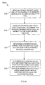
- Figure 3 is a flow chart of an exemplary method 300 of operating a gas turbine engine in accordance with an embodiment of the present invention.
- method 300 includes receiving 302 a signal from at least one of a plurality of sensors indicative of a composition of a fuel for the gas turbine engine.
- a flow model is used 304 with the at least one signal to determine the physical properties of the fuel at an inlet to fuel flow control devices.
- Method 300 also includes determining 306 a corresponding correction to a gas fuel flow gain using the determined physical properties and automatically controlling 308 fuel delivery as well as fuel split between the fuel injection points on the combustor using the adjusted flow gain to facilitate permitting a relatively large variation in the fuel composition for use in the gas turbine engine.
- the above-described methods and apparatus provide a cost-effective and reliable means for automatically and continuously determining the physical properties of a fuel gas at the gas control valve inlet using a flow model and determining a corresponding correction to a gas fuel flow gain from those physical properties.
- the methods and apparatus described herein facilitate gas turbine engine operation in a cost-effective and reliable manner.
- Exemplary methods and apparatus for automatically and continuously determining the physical properties of a fuel gas at the gas control valve inlet using a flow model and determining a corresponding correction to a gas fuel flow gain are described above in detail.
- the apparatus illustrated is not limited to the specific embodiments described herein, but rather, components of each may be utilized independently and separately from other components described herein. Each system component can also be used in combination with other system components.
- One technical effect of the method and apparatus described herein is to provide a system that automatically and continuously determines the physical properties of a fuel gas at the gas control valve inlet using a flow model and determining a corresponding adjustment to a gas fuel flow gain from those physical properties to permit a relatively large variation in the fuel composition for use in the gas turbine engine.
Landscapes
- Engineering & Computer Science (AREA)
- Chemical & Material Sciences (AREA)
- Combustion & Propulsion (AREA)
- Mechanical Engineering (AREA)
- General Engineering & Computer Science (AREA)
- Quality & Reliability (AREA)
- Physics & Mathematics (AREA)
- Electromagnetism (AREA)
- Computer Networks & Wireless Communication (AREA)
- Signal Processing (AREA)
- Engine Equipment That Uses Special Cycles (AREA)
- Control Of Turbines (AREA)
Applications Claiming Priority (1)
| Application Number | Priority Date | Filing Date | Title |
|---|---|---|---|
| US12/026,230 US7966802B2 (en) | 2008-02-05 | 2008-02-05 | Methods and apparatus for operating gas turbine engine systems |
Publications (2)
| Publication Number | Publication Date |
|---|---|
| EP2088288A2 true EP2088288A2 (de) | 2009-08-12 |
| EP2088288A3 EP2088288A3 (de) | 2016-04-20 |
Family
ID=40911102
Family Applications (1)
| Application Number | Title | Priority Date | Filing Date |
|---|---|---|---|
| EP09151741.7A Withdrawn EP2088288A3 (de) | 2008-02-05 | 2009-01-30 | Gasturbinensystem |
Country Status (4)
| Country | Link |
|---|---|
| US (1) | US7966802B2 (de) |
| EP (1) | EP2088288A3 (de) |
| JP (1) | JP5379502B2 (de) |
| CN (1) | CN101539056B (de) |
Cited By (3)
| Publication number | Priority date | Publication date | Assignee | Title |
|---|---|---|---|---|
| US20160115839A1 (en) * | 2014-10-28 | 2016-04-28 | General Electric Company | System and method for emissions control in gas turbine systems |
| US9791351B2 (en) | 2015-02-06 | 2017-10-17 | General Electric Company | Gas turbine combustion profile monitoring |
| GB2601500A (en) * | 2020-12-01 | 2022-06-08 | Siemens Energy Global Gmbh & Co Kg | Method of Controlling a Combustor |
Families Citing this family (49)
| Publication number | Priority date | Publication date | Assignee | Title |
|---|---|---|---|---|
| US20100205976A1 (en) * | 2008-08-26 | 2010-08-19 | Pratyush Nag | Integrated fuel gas characterization system |
| US9267443B2 (en) | 2009-05-08 | 2016-02-23 | Gas Turbine Efficiency Sweden Ab | Automated tuning of gas turbine combustion systems |
| US9671797B2 (en) | 2009-05-08 | 2017-06-06 | Gas Turbine Efficiency Sweden Ab | Optimization of gas turbine combustion systems low load performance on simple cycle and heat recovery steam generator applications |
| US8437941B2 (en) | 2009-05-08 | 2013-05-07 | Gas Turbine Efficiency Sweden Ab | Automated tuning of gas turbine combustion systems |
| US9354618B2 (en) | 2009-05-08 | 2016-05-31 | Gas Turbine Efficiency Sweden Ab | Automated tuning of multiple fuel gas turbine combustion systems |
| BRPI1007723A2 (pt) | 2009-05-12 | 2018-03-06 | Icr Turbine Engine Corp | sistema de armazenamento e conversão de turbina a gás |
| US8234874B2 (en) * | 2009-10-09 | 2012-08-07 | General Electric Company | Systems and methods for bypassing an inlet air treatment filter |
| FR2951540B1 (fr) * | 2009-10-19 | 2012-06-01 | Turbomeca | Test de non-extinction pour chambre de combustion de turbomachine |
| IT1396514B1 (it) * | 2009-11-27 | 2012-12-14 | Nuovo Pignone Spa | Metodo di controllo di turbina basato su rapporto tra temperatura di scarico e pressione di turbina |
| US8866334B2 (en) | 2010-03-02 | 2014-10-21 | Icr Turbine Engine Corporation | Dispatchable power from a renewable energy facility |
| US20110232313A1 (en) * | 2010-03-24 | 2011-09-29 | General Electric Company | Chiller Condensate System |
| US8731797B2 (en) * | 2010-04-30 | 2014-05-20 | Alstom Technology Ltd. | Employing fuel properties to auto-tune a gas turbine engine |
| US8984895B2 (en) | 2010-07-09 | 2015-03-24 | Icr Turbine Engine Corporation | Metallic ceramic spool for a gas turbine engine |
| US8669670B2 (en) | 2010-09-03 | 2014-03-11 | Icr Turbine Engine Corporation | Gas turbine engine configurations |
| US8850818B2 (en) * | 2010-10-18 | 2014-10-07 | General Electric Company | Systems and methods for gas fuel delivery with hydrocarbon removal utilizing active pressure control and dew point analysis |
| US9051873B2 (en) | 2011-05-20 | 2015-06-09 | Icr Turbine Engine Corporation | Ceramic-to-metal turbine shaft attachment |
| US9903231B2 (en) * | 2011-12-14 | 2018-02-27 | General Electric Company | System and method for warming up a steam turbine |
| CN102518518A (zh) * | 2011-12-28 | 2012-06-27 | 山西太钢不锈钢股份有限公司 | 燃料输送系统和燃机采用主燃料代替值班燃料的方法 |
| CH705965A1 (de) * | 2012-01-09 | 2013-07-15 | Alstom Technology Ltd | Verfahren zum Betrieb einer Gasturbine. |
| ITCO20120007A1 (it) * | 2012-02-21 | 2013-08-22 | Nuovo Pignone Srl | Dispositivo di filtraggio dell'aria in ingresso per un impianto |
| US9458734B2 (en) * | 2012-06-08 | 2016-10-04 | General Electric Company | Model and simulation based control of turbines |
| US10094288B2 (en) | 2012-07-24 | 2018-10-09 | Icr Turbine Engine Corporation | Ceramic-to-metal turbine volute attachment for a gas turbine engine |
| CN102852647B (zh) * | 2012-09-28 | 2014-06-25 | 中国科学院自动化研究所 | 一种小型涡喷发动机控制方法 |
| US20140182298A1 (en) * | 2012-12-28 | 2014-07-03 | Exxonmobil Upstream Research Company | Stoichiometric combustion control for gas turbine system with exhaust gas recirculation |
| US9243567B2 (en) * | 2012-11-27 | 2016-01-26 | General Electric Company | System and method to control a gas turbine subject to fuel composition variation |
| EP2738373A1 (de) * | 2012-12-03 | 2014-06-04 | Siemens Aktiengesellschaft | Gasturbinen-Brennstoffzufuhrverfahren und -anordnung |
| US9810156B2 (en) * | 2012-12-18 | 2017-11-07 | General Electric Company | Systems and methods for controlling mode transfers of a combustor |
| EP2770182B1 (de) | 2013-02-25 | 2015-10-14 | Alstom Technology Ltd | Verfahren zur Anpassung der Temperatur von Erdgas für eine Kraftstoffversorgungsleitung einer Gasturbine sowie Gasturbine |
| JP6005252B2 (ja) * | 2013-02-26 | 2016-10-12 | 三菱日立パワーシステムズ株式会社 | ガスタービンシステム、制御装置及びガスタービンの運転方法 |
| US9562479B2 (en) | 2013-03-13 | 2017-02-07 | General Electric Company | Systems and methods of droop response control of turbines |
| US9377202B2 (en) | 2013-03-15 | 2016-06-28 | General Electric Company | System and method for fuel blending and control in gas turbines |
| US9382850B2 (en) | 2013-03-21 | 2016-07-05 | General Electric Company | System and method for controlled fuel blending in gas turbines |
| JP6190670B2 (ja) * | 2013-08-30 | 2017-08-30 | 三菱日立パワーシステムズ株式会社 | ガスタービン燃焼システム |
| US9850823B2 (en) * | 2013-12-26 | 2017-12-26 | Siemens Aktiengesellschaft | Control system and method for controlling a gas turbine engine during transients |
| CN103775214A (zh) * | 2014-01-28 | 2014-05-07 | 中节能工业节能有限公司 | 燃机吹扫管线监控装置 |
| US9790834B2 (en) | 2014-03-20 | 2017-10-17 | General Electric Company | Method of monitoring for combustion anomalies in a gas turbomachine and a gas turbomachine including a combustion anomaly detection system |
| JP6257035B2 (ja) * | 2014-03-25 | 2018-01-10 | 三菱日立パワーシステムズ株式会社 | ガスタービンの燃焼制御装置および燃焼制御方法並びにプログラム |
| US10221777B2 (en) * | 2014-03-25 | 2019-03-05 | Mitsubishi Hitachi Power Systems, Ltd. | Gas turbine combustion control device and combustion control method and program therefor |
| JP6364363B2 (ja) * | 2015-02-23 | 2018-07-25 | 三菱日立パワーシステムズ株式会社 | 2軸式ガスタービン及びその制御装置と制御方法 |
| CN104989954B (zh) * | 2015-07-08 | 2019-03-29 | 内蒙古包钢钢联股份有限公司 | 用于清理ccpp机组焦煤流量调阀卡涩的装置及方法 |
| US20170051682A1 (en) * | 2015-08-20 | 2017-02-23 | General Electric Company | System and method for abatement of dynamic property changes with proactive diagnostics and conditioning |
| NL2015818B1 (en) * | 2015-11-19 | 2017-06-06 | Host B V | Method and gas refining installation for providing a gas stream having a wobbe index within a required range. |
| WO2017196293A1 (en) | 2016-05-09 | 2017-11-16 | Cummins Inc. | Fuel type prediction from mass flow measurements and thermal conductivity sensor |
| CN109654534B (zh) * | 2018-10-19 | 2020-10-20 | 华电电力科学研究院有限公司 | 一种dln1.0燃烧系统的燃烧调整方法 |
| US11333082B2 (en) * | 2020-06-12 | 2022-05-17 | General Electric Company | Systems and methods for determination of gas turbine fuel split for head end temperature control |
| US11885270B2 (en) | 2021-09-22 | 2024-01-30 | Michael D. Mercer | Energy utilization system |
| US12486812B2 (en) | 2021-09-22 | 2025-12-02 | Bedrock Ventures LLC | Standby fuel storage system for uninterrupted operation during primary fuel curtailment |
| CN114635801B (zh) * | 2022-03-23 | 2023-11-21 | 合肥工业大学 | 一种燃气发生器的背压特性优化方法及装置 |
| WO2026048185A1 (ja) * | 2024-08-30 | 2026-03-05 | 三菱パワー株式会社 | 燃料制御装置、燃料制御方法、及びプログラム |
Family Cites Families (30)
| Publication number | Priority date | Publication date | Assignee | Title |
|---|---|---|---|---|
| US4735052A (en) * | 1985-09-30 | 1988-04-05 | Kabushiki Kaisha Toshiba | Gas turbine apparatus |
| US4761948A (en) * | 1987-04-09 | 1988-08-09 | Solar Turbines Incorporated | Wide range gaseous fuel combustion system for gas turbine engines |
| US5288149A (en) * | 1992-03-12 | 1994-02-22 | Panametrics, Inc. | Gas calorimeter and wobbe index meter |
| JPH08246903A (ja) * | 1995-03-07 | 1996-09-24 | Hitachi Ltd | ガスタービン発電装置およびその制御方法 |
| GB9520002D0 (en) | 1995-09-30 | 1995-12-06 | Rolls Royce Plc | Turbine engine control system |
| JP3827783B2 (ja) * | 1996-10-23 | 2006-09-27 | 株式会社東芝 | ガスタービンの制御装置 |
| DE59909192D1 (de) * | 1998-09-10 | 2004-05-19 | Siemens Ag | Verfahren zum betrieb eines brenners und brenneranordnung |
| US6230103B1 (en) | 1998-11-18 | 2001-05-08 | Power Tech Associates, Inc. | Method of determining concentration of exhaust components in a gas turbine engine |
| US6813875B2 (en) | 2000-01-07 | 2004-11-09 | Honda Giken Kogyo Kabushiki Kaisha | Control system for gas-turbine engine |
| US6694744B1 (en) * | 2000-11-09 | 2004-02-24 | General Electric Company | Fuel gas moisturization system level control |
| US6655151B2 (en) | 2001-09-07 | 2003-12-02 | Honeywell International, Inc. | Method for controlling fuel flow to a gas turbine engine |
| JP4495971B2 (ja) * | 2002-01-25 | 2010-07-07 | アルストム テクノロジー リミテッド | ガスタービン群を運転するための方法 |
| GB2397395B (en) | 2003-01-16 | 2006-04-05 | Rolls Royce Plc | Controlling the fuel supply to a combustor of a gas turbine engine |
| DE10345566A1 (de) * | 2003-09-29 | 2005-04-28 | Alstom Technology Ltd Baden | Verfahren zum Betrieb einer Gasturbine sowie Gasturbinenanlage zur Durchführung des Verfahrens |
| EP1524423A1 (de) * | 2003-10-13 | 2005-04-20 | Siemens Aktiengesellschaft | Verfahren und Vorrichung zum Ausgleichen von Schwankungen der Brennstoffzusammensetzung in einer Gasturbinenanlage |
| FR2871520B1 (fr) | 2004-06-15 | 2008-12-26 | Eurocopter France | Indicateur de pilotage permettant de predire l'evolution des parametres de surveillance d'un turbomoteur |
| JP4592513B2 (ja) * | 2004-09-30 | 2010-12-01 | 三菱重工業株式会社 | ガスタービン制御装置、及びガスタービンシステム |
| EP1645804A1 (de) * | 2004-10-11 | 2006-04-12 | Siemens Aktiengesellschaft | Verfahren zum Betrieb eines Brenners, insbesondere eines Brenners einer Gasturbine, sowie Vorrichtung zur Durchführung des Verfahrens |
| GB0502608D0 (en) | 2005-02-09 | 2005-03-16 | Rolls Royce Plc | A fuel processor |
| US7395670B1 (en) * | 2005-02-18 | 2008-07-08 | Praxair Technology, Inc. | Gas turbine fuel preparation and introduction method |
| JP4765440B2 (ja) | 2005-07-05 | 2011-09-07 | 日産自動車株式会社 | エンジンの燃料供給方法及びエンジンの燃料供給装置 |
| US7565805B2 (en) * | 2005-11-22 | 2009-07-28 | General Electric Company | Method for operating gas turbine engine systems |
| US7540141B2 (en) | 2005-12-13 | 2009-06-02 | Hamilton Sundstrand Corporation | Smart fuel control system |
| JP5193197B2 (ja) * | 2006-07-06 | 2013-05-08 | アルストム テクノロジー リミテッド | ガスタービン作動方法ならびに当該方法を実施するためのガスタービン |
| GB2440757B (en) | 2006-08-10 | 2008-12-24 | Rolls Royce Plc | Controlling fuel supply to a combustor of a gas turbine engine |
| US7854110B2 (en) * | 2006-11-16 | 2010-12-21 | Siemens Energy, Inc. | Integrated fuel gas characterization system |
| JP4831836B2 (ja) * | 2007-12-13 | 2011-12-07 | 三菱重工業株式会社 | ガスタービンの制御方法およびガスタービン発電装置 |
| US8126629B2 (en) * | 2008-04-25 | 2012-02-28 | General Electric Company | Method and system for operating gas turbine engine systems |
| US7895821B2 (en) * | 2008-12-31 | 2011-03-01 | General Electric Company | System and method for automatic fuel blending and control for combustion gas turbine |
| US8356484B2 (en) * | 2009-05-01 | 2013-01-22 | General Electric Company | Hybrid Wobbe control during rapid response startup |
-
2008
- 2008-02-05 US US12/026,230 patent/US7966802B2/en not_active Expired - Fee Related
-
2009
- 2009-01-30 EP EP09151741.7A patent/EP2088288A3/de not_active Withdrawn
- 2009-02-04 JP JP2009023196A patent/JP5379502B2/ja not_active Expired - Fee Related
- 2009-02-05 CN CN200910004070.3A patent/CN101539056B/zh not_active Expired - Fee Related
Non-Patent Citations (1)
| Title |
|---|
| None * |
Cited By (5)
| Publication number | Priority date | Publication date | Assignee | Title |
|---|---|---|---|---|
| US20160115839A1 (en) * | 2014-10-28 | 2016-04-28 | General Electric Company | System and method for emissions control in gas turbine systems |
| US10006330B2 (en) * | 2014-10-28 | 2018-06-26 | General Electric Company | System and method for emissions control in gas turbine systems |
| US9791351B2 (en) | 2015-02-06 | 2017-10-17 | General Electric Company | Gas turbine combustion profile monitoring |
| GB2601500A (en) * | 2020-12-01 | 2022-06-08 | Siemens Energy Global Gmbh & Co Kg | Method of Controlling a Combustor |
| US12006881B2 (en) | 2020-12-01 | 2024-06-11 | Siemens Energy Global GmbH & Co. KG | Method of controlling a combustor |
Also Published As
| Publication number | Publication date |
|---|---|
| JP5379502B2 (ja) | 2013-12-25 |
| JP2009216085A (ja) | 2009-09-24 |
| US20090193788A1 (en) | 2009-08-06 |
| CN101539056B (zh) | 2014-10-15 |
| US7966802B2 (en) | 2011-06-28 |
| EP2088288A3 (de) | 2016-04-20 |
| CN101539056A (zh) | 2009-09-23 |
Similar Documents
| Publication | Publication Date | Title |
|---|---|---|
| US7966802B2 (en) | Methods and apparatus for operating gas turbine engine systems | |
| CN1971013B (zh) | 用于操作燃气轮机系统的方法和装置 | |
| US8126629B2 (en) | Method and system for operating gas turbine engine systems | |
| CN101358555B (zh) | 通过在线燃料重整来进行沃泊控制和增强可操作性 | |
| US20120036863A1 (en) | Method, apparatus and system for delivery of wide range of turbine fuels for combustion | |
| EP2504545B1 (de) | Auf abgastemperatur basierender grenzwert für ein steuerverfahren und turbine | |
| US20130019607A1 (en) | Exhasust temperature versus turbine pressure ratio based turbine control method and device | |
| US7905082B2 (en) | Method and system for increasing Modified Wobbe Index control range | |
| US11208959B2 (en) | System and method for flexible fuel usage for gas turbines | |
| ITCO20090054A1 (it) | Metodo di controllo di modo basato su temperatura di scarico per turbina a gas e turbina a gas | |
| US11746712B2 (en) | Controller and method | |
| US11655769B2 (en) | Controller and method for controlling a gas turbine | |
| CN102947572B (zh) | 起动或停止燃气涡轮发动机的方法和设备 | |
| JP2013249755A (ja) | 高湿分空気利用ガスタービン |
Legal Events
| Date | Code | Title | Description |
|---|---|---|---|
| PUAI | Public reference made under article 153(3) epc to a published international application that has entered the european phase |
Free format text: ORIGINAL CODE: 0009012 |
|
| AK | Designated contracting states |
Kind code of ref document: A2 Designated state(s): AT BE BG CH CY CZ DE DK EE ES FI FR GB GR HR HU IE IS IT LI LT LU LV MC MK MT NL NO PL PT RO SE SI SK TR |
|
| AX | Request for extension of the european patent |
Extension state: AL BA RS |
|
| PUAL | Search report despatched |
Free format text: ORIGINAL CODE: 0009013 |
|
| AK | Designated contracting states |
Kind code of ref document: A3 Designated state(s): AT BE BG CH CY CZ DE DK EE ES FI FR GB GR HR HU IE IS IT LI LT LU LV MC MK MT NL NO PL PT RO SE SI SK TR |
|
| AX | Request for extension of the european patent |
Extension state: AL BA RS |
|
| RIC1 | Information provided on ipc code assigned before grant |
Ipc: F02C 7/232 20060101ALI20160311BHEP Ipc: F02C 9/28 20060101ALI20160311BHEP Ipc: F01D 15/10 20060101AFI20160311BHEP Ipc: F02C 7/22 20060101ALI20160311BHEP Ipc: F02C 9/26 20060101ALI20160311BHEP |
|
| 17P | Request for examination filed |
Effective date: 20161020 |
|
| RBV | Designated contracting states (corrected) |
Designated state(s): AT BE BG CH CY CZ DE DK EE ES FI FR GB GR HR HU IE IS IT LI LT LU LV MC MK MT NL NO PL PT RO SE SI SK TR |
|
| AKX | Designation fees paid |
Designated state(s): AT BE BG CH CY CZ DE DK EE ES FI FR GB GR HR HU IE IS IT LI LT LU LV MC MK MT NL NO PL PT RO SE SI SK TR |
|
| AXX | Extension fees paid |
Extension state: RS Extension state: AL Extension state: BA |
|
| 17Q | First examination report despatched |
Effective date: 20170516 |
|
| STAA | Information on the status of an ep patent application or granted ep patent |
Free format text: STATUS: THE APPLICATION IS DEEMED TO BE WITHDRAWN |
|
| 18D | Application deemed to be withdrawn |
Effective date: 20170927 |