EP2088610B1 - Kammer zum Aufnehmen und zur Trennung von Schaltern und Schalteinheiten - Google Patents
Kammer zum Aufnehmen und zur Trennung von Schaltern und Schalteinheiten Download PDFInfo
- Publication number
- EP2088610B1 EP2088610B1 EP08425071A EP08425071A EP2088610B1 EP 2088610 B1 EP2088610 B1 EP 2088610B1 EP 08425071 A EP08425071 A EP 08425071A EP 08425071 A EP08425071 A EP 08425071A EP 2088610 B1 EP2088610 B1 EP 2088610B1
- Authority
- EP
- European Patent Office
- Prior art keywords
- compartment
- switch
- cover
- terminal board
- frame
- Prior art date
- Legal status (The legal status is an assumption and is not a legal conclusion. Google has not performed a legal analysis and makes no representation as to the accuracy of the status listed.)
- Not-in-force
Links
- 238000005204 segregation Methods 0.000 title claims abstract description 7
- 238000003780 insertion Methods 0.000 claims abstract description 21
- 230000037431 insertion Effects 0.000 claims abstract description 21
- 230000000903 blocking effect Effects 0.000 claims description 2
- 230000008878 coupling Effects 0.000 claims description 2
- 238000010168 coupling process Methods 0.000 claims description 2
- 238000005859 coupling reaction Methods 0.000 claims description 2
- 238000000605 extraction Methods 0.000 claims description 2
- 238000012423 maintenance Methods 0.000 description 2
- 230000000295 complement effect Effects 0.000 description 1
- 239000000428 dust Substances 0.000 description 1
- 230000008595 infiltration Effects 0.000 description 1
- 238000001764 infiltration Methods 0.000 description 1
- 230000002452 interceptive effect Effects 0.000 description 1
- 239000007788 liquid Substances 0.000 description 1
- 239000000463 material Substances 0.000 description 1
- 238000012986 modification Methods 0.000 description 1
- 230000004048 modification Effects 0.000 description 1
Images


Classifications
-
- H—ELECTRICITY
- H01—ELECTRIC ELEMENTS
- H01H—ELECTRIC SWITCHES; RELAYS; SELECTORS; EMERGENCY PROTECTIVE DEVICES
- H01H71/00—Details of the protective switches or relays covered by groups H01H73/00 - H01H83/00
- H01H71/02—Housings; Casings; Bases; Mountings
- H01H71/0264—Mountings or coverplates for complete assembled circuit breakers, e.g. snap mounting in panel
-
- H—ELECTRICITY
- H01—ELECTRIC ELEMENTS
- H01H—ELECTRIC SWITCHES; RELAYS; SELECTORS; EMERGENCY PROTECTIVE DEVICES
- H01H9/00—Details of switching devices, not covered by groups H01H1/00 - H01H7/00
- H01H9/02—Bases, casings, or covers
- H01H9/0264—Protective covers for terminals
Definitions
- the present invention regards a containment compartment for a switch, especially a boxed switch, and a switch unit.
- the base is attached mechanically to the electrical panel and is connected electrically inside the electrical panel to an electric system which the switch is to be connected to.
- the base includes electrical connection terminals to enable the connection of the switch to an electric circuit, such as a line circuit or load circuit.
- the electrical panel is a structure built-in to the wall closed off by a panel which when opened permits access to the switch.
- the aim of this invention is to overcome the drawbacks mentioned with reference to the technical note.
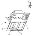
- the reference numeral 4 globally denotes a containment and segregation compartment for switches.
- the compartment 4 is suitable for inserting in a recess 6 of an electrical panel 8 fitted with a base 12 and an opening/closing hatch 16.
- the opening/closing hatch 16 can be removable from the panel 8 or attached to the panel 8 for example by a hinge, so that it can be opened.
- the recess 6 of the panel 8 is included between the base 12 and the hatch 16, and is able to accommodate at least one electric switch 20 through an aperture 7 on the front of the hatch 16.
- the switch 20 is attached to the electrical panel 8 by means of an insertion terminal board 24.
- the insertion terminal board 24 can be attached to the base 12 of the electrical panel 8 by interposing an attachment panel, for example, parallel to the base 12, or by interposing a small support frame comprising uprights and/ or crossbeams and relative threaded means of connection.
- the compartment 4 is advantageously situated between the switch 20 and a relative insertion terminal board 24.
- the insertion terminal board 24 comprises electric connection terminals 28 to a line circuit and/or load circuit able to receive complementary electric terminals of the associable switch 20.
- the compartment 4 comprises a frame 32 which defines a site of containment 36 able to accommodate at least partially the insertion terminal board 24 and the switch 20.
- the frame 32 is overall a box-like structure comprising a first and a second upright 40,44 as well upper crossbeam 48 and a lower crossbeam 52.
- the uprights 40,44 and the crossbeams 48,52 form a closed loop which define the site of containment.
- the frame 32 is open at a rear portion 56, able to interface with the insertion terminal board 24, and a front portion 60 able to receive the associable switch 20.
- the frame 32 is shaped so as to fit exactly against the insertion terminal board 24 so as to prevent access to the live parts adjacent to the terminal board 24.
- the frame 32 is shaped so as to fit exactly against the insertion terminal board 24 so that after having fitted the compartment 4 on to the terminal board 24, the latter is covered around its perimeter by the compartment 4.
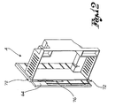
- the frame 32 comprises a closure cover 64 able to close off the front portion 60, so as to close off access to the site of containment 36.
- the closure cover 64 can be moved independently of the hatch 16 of the electrical panel 8, so as to allow access to the site of containment 36 without having to open or remove the hatch 16 of the electrical panel 8.
- the closure cover 64 is mechanically separate from the hatch 16 of the electrical panel 8.
- the cover 64 in a closed configuration, sits flush with the front portion 60 of the compartment 4.
- the frame 32 of the compartment 4 comprises a housing recess 68 able to house at least partially the cover 64 of the compartment 4, in an open configuration of the cover 64.
- the housing recess is preferably situated in a position adjacent to an upright 40,44 of the frame 32, and preferably at the height of the upright at which the cover 64 is hinged.
- the closure cover 64 is therefore hinged to an upright 40,44 of the frame 32 so as to move in a rotatory movement in relation to said upright 40.
- Said closure cover 64 can for example rotate by 90 degrees and sit, in an open configuration, essentially perpendicular to the front portion 60 of the frame 32 or it can for example rotate 180 degrees to sit parallel to the front portion 60 ( figure 11 ).
- the closure cover 64 is attached to an upright 40,44 of the frame 32 by means of a rotor-translatory coupling, so as to be able to rotate in relation to an axis of the hinge X-X essentially parallel to the relative upright 40,44 and be able to translate in a perpendicular direction to the same axis of the hinge X-X, inserting itself at least partially inside the housing recess 68 ( figure 12 ).
- the housing recess 68 comprises insertion guides 72 of the cover 64 able to guide the cover inside the housing recess 68.
- the cover 64 of the compartment 4 presents an aperture 76 able to receive a protruding front portion 80 of the switch 20 fitted with a control lever 84, so as to be able to activate the control lever 84 of the switch 20 even when the cover 64 of the compartment 4 is closed.
- the cover 64 of the compartment 4 is fitted with a flap 88 able to close said aperture 76 of the cover 64 of the compartment 4, so as to prevent access inside the panel 8 following removal of the switch 20.
- the flap 88 is sliding and is situated adjacent to the aperture 76 of the closure cover 64 of the compartment 4.
- the flap 88 slides along an upper edge 92 which defines the aperture 76, according to a shutter movement.
- the flap 88 comprises a handle 96 to facilitate moving of the flap 88.
- the flap 88 comprises means of blocking, able to block the flap 88 in the open and/or closed position; according to a possible form of embodiment the flap 88 is fitted with a spring which keeps it automatically in the closed position when the switch 20 is not on.
- the compartment makes it possible to prevent accidental contact between an operator and the live parts of the terminal board, given that the compartment is shaped to fit exactly against the terminal board and is made in electrically insulated material.
- the operator can easily work on the switch inside the electrical panel, without interfering with the closure hatch of the panel which can be conveniently put away in the relative housing recess.
- closure hatch of the electrical panel can remain closed and the closure cover of the compartment, after being opened, can be conveniently inserted out of sight into the compartment housing recess. This way the operator has more space for manoeuvring.
Landscapes
- Switch Cases, Indication, And Locking (AREA)
- Distribution Board (AREA)
- Connector Housings Or Holding Contact Members (AREA)
- Patch Boards (AREA)
Claims (13)
- Kammer zum Aufnehmen und zur Trennung von Schaltern (4), die geeignet ist, in eine elektrische Platte (8) eingesetzt zu werden und zwischen einem elektrischen Schalter (20) und einer jeweiligen Einsatzanschlussplatte (24) im Inneren der elektrischen Platte (8) positioniert zu werden, wobei der Schalter (20) und die Einsatzanschlussplatte (24) elektrische Verbindungsanschlüsse (28) zu einer Leitung und/oder einer Lastschaltung umfassen, wobei die Kammer (4) umfasst:- einen Rahmen (32) der ein Gebiet für die Aufnahme (36) definiert, das fähig ist, die Einsatzanschlussplatte (24) und den Schalter (20) wenigstens teilweise aufzunehmen;- wobei der Rahmen (32) derart geformt ist, dass er genau gegen die Einsatzanschlussplatte (24) passt, um den Zugriff auf die aktiven elektrischen Teile benachbart zu der Einsatzanschlussplatte (24) zu verhindern,- und wobei der Rahmen (32) einen Verschlussdeckel (64) umfasst, der fähig ist, den Zugriff auf das Aufnahmegebiet (36) abzusperren, wobei der Deckel (64) unabhängig von der Öffnungs-/Schließluke (16) der elektrischen Platte (8) beweglich ist, um den Zugriff auf das Aufnahmegebiet (8) zuzulassen, ohne die Luke (16) der elektrischen Platte (16) öffnen oder schließen zu müssen, wobei der Deckel der Kammer (64) eine Öffnung (76) aufweist, die fähig ist, einen vorstehenden vorderen Abschnitt (80) des Schalters (20) aufzunehmen, der mit einem Steuerhebel (84) ausgestattet ist, um fähig zu sein, den Steuerhebel (84) des Schalters (20) zu betätigen, selbst wenn die Abdeckung (64) der Kammer (4) geschlossen ist,dadurch gekennzeichnet, dass
der Deckel (64) der Kammer (4) mit einer Klappe (88) ausgestattet ist, die fähig ist, die Öffnung (76) des Deckels (64) der Kammer (4) zu schließen, um den Zugriff auf die elektrische Platte (8) nach dem Entfernen des Schalters (20) zu verhindern. - Kammer (4) nach Anspruch 1, wobei der Verschlussdeckel in einer geschlossenen Anordnung bündig mit einem vorderen Abschnitt (60) der Kammer (4) sitzt, um den Zugriff auf die auf das Aufnahmegebiet (36) des Schalters (20) zu verhindern.
- Kammer (4) nach Anspruch 1 oder 2, wobei der Verschlussdeckel (64) derart geformt ist, dass er gegen ein vorderes Loch (7) der Luke (16) der elektrischen Platte passt, das fähig ist, das Einsetzen und Entnehmen des Schalters (20) zuzulassen.
- Kammer (4) nach einem der vorhergehenden Ansprüche, wobei der Rahmen (32) der Kammer (4) eine Gehäuseaussparung (68) umfasst, die fähig ist, den Verschlussdeckel (64) der Kammer (4) in einer offenen Anordnung des Deckels (64) wenigstens teilweise unterzubringen.
- Kammer (4) nach Anspruch 4, wobei die Gehäuseaussparung (68) sich benachbart zu einem Pfosten (40, 44) des Rahmens (32) befindet.
- Kammer (4) nach Anspruch 5, wobei der Verschlussdeckel (64) an dem Pfosten (40, 44) des Rahmens (32) eingehängt ist, um fähig zu sein, in einer offenen Anordnung im Inneren der Gehäuseaussparung (68) zu gleiten.
- Kammer (4) nach einem der Ansprüche 4 bis 6, wobei der Verschlussdeckel (64) mittels einer Rotor-Umsetzer-Kopplung mit einem Pfosten (40, 44) des Rahmens (4) verbunden ist, um fähig zu sein, sich in einer offenen Anordnung selbst in das Innere der Gehäuseaussparung (68) einzusetzen.
- Kammer (4) nach einem der vorhergehenden Ansprüche 4 bis 7, wobei die Gehäuseaussparung (68) Einsetzführungen (72) des Deckels (64) umfasst.
- Kammer (4) nach Anspruch 1, wobei die Klappe (88) gleitet und benachbart zu der Öffnung (76) des Verschlussdeckels (64) der Kammer (4) angeordnet ist.
- Kammer (4) nach Anspruch 1 oder 9, wobei die Klappe (88) entlang eines oberen Rands (92) gleitet, der die Öffnung (76) definiert, um die Öffnung (76) entsprechend einer Verschlussbewegung zu verschließen.
- Kammer (4) nach den Ansprüchen 1, 9 oder 10, wobei die Klappe (88) einen Griff (96) umfasst, um die Bewegung der Klappe (88) zu erleichtern.
- Kammer (4) nach einem der vorhergehenden Ansprüche 1, 9, 10, 11, wobei die Klappe (88) ein Blockierungsmittel umfasst, das fähig ist, die Klappe (88) in der offenen und/oder geschlossenen Position zu blockieren.
- Schalteinheit, die eine Kammer (4) nach einem der vorhergehenden Ansprüche von 1 bis 12, eine Einsatzanschlussplatte (24) und einen mit der Einsatzanschlussplatte (24) elektrisch verbundenen Schalter (20) umfasst, wobei die Kammer (4) zwischen der Einsatzanschlussplatte (24) und dem Schalter (20) angeordnet ist.
Priority Applications (6)
| Application Number | Priority Date | Filing Date | Title |
|---|---|---|---|
| EP08425071A EP2088610B1 (de) | 2008-02-07 | 2008-02-07 | Kammer zum Aufnehmen und zur Trennung von Schaltern und Schalteinheiten |
| AT08425071T ATE553493T1 (de) | 2008-02-07 | 2008-02-07 | Kammer zum aufnehmen und zur trennung von schaltern und schalteinheiten |
| CN200910005313.5A CN101505037B (zh) | 2008-02-07 | 2009-02-05 | 用于开关及开关单元的容纳及分隔箱 |
| CL2009000251A CL2009000251A1 (es) | 2008-02-07 | 2009-02-05 | Bandeja de contencion para interruptores que se puede introducir en un panel electrico, que comprende un armazon, con una puerta dotada de una portezuela para cerrar una abertura que recibe una porcion saliente del interruptor, de manera de impedir el acceso al panel luego de retirar el interruptor |
| CO09011553A CO6190095A1 (es) | 2008-02-07 | 2009-02-06 | Bandeja de contencion y segregacion para interruptures y grupo interruptor |
| RU2009104147/07A RU2488908C2 (ru) | 2008-02-07 | 2009-02-06 | Отсек для защиты и изоляции переключателя и блока переключателей |
Applications Claiming Priority (1)
| Application Number | Priority Date | Filing Date | Title |
|---|---|---|---|
| EP08425071A EP2088610B1 (de) | 2008-02-07 | 2008-02-07 | Kammer zum Aufnehmen und zur Trennung von Schaltern und Schalteinheiten |
Publications (2)
| Publication Number | Publication Date |
|---|---|
| EP2088610A1 EP2088610A1 (de) | 2009-08-12 |
| EP2088610B1 true EP2088610B1 (de) | 2012-04-11 |
Family
ID=39637623
Family Applications (1)
| Application Number | Title | Priority Date | Filing Date |
|---|---|---|---|
| EP08425071A Not-in-force EP2088610B1 (de) | 2008-02-07 | 2008-02-07 | Kammer zum Aufnehmen und zur Trennung von Schaltern und Schalteinheiten |
Country Status (6)
| Country | Link |
|---|---|
| EP (1) | EP2088610B1 (de) |
| CN (1) | CN101505037B (de) |
| AT (1) | ATE553493T1 (de) |
| CL (1) | CL2009000251A1 (de) |
| CO (1) | CO6190095A1 (de) |
| RU (1) | RU2488908C2 (de) |
Families Citing this family (3)
| Publication number | Priority date | Publication date | Assignee | Title |
|---|---|---|---|---|
| CN102412083A (zh) * | 2010-09-20 | 2012-04-11 | 西门子公司 | 一种用于隔离开关插入单元的侧板装置及其插入单元 |
| WO2019041234A1 (zh) * | 2017-08-31 | 2019-03-07 | 深圳昂泰智能有限公司 | 防触电保护装置、配电功能模块及配电设备 |
| CN113972101A (zh) * | 2020-07-24 | 2022-01-25 | 江苏怡通控制系统有限公司 | 一种自动型电流保护器 |
Family Cites Families (7)
| Publication number | Priority date | Publication date | Assignee | Title |
|---|---|---|---|---|
| US4142225A (en) * | 1977-10-17 | 1979-02-27 | Square D Company | Panelboard assembly employing heat transmitting insulator assembly and a circuit breaker securing bead received in a circuit breaker housing recess |
| US4752233A (en) * | 1987-07-20 | 1988-06-21 | General Electric Company | Electric power panelboard adapter module |
| US5172300A (en) * | 1989-08-02 | 1992-12-15 | General Electric Company | Electric power distribution panelboard-switchboard assembly |
| US5894404A (en) * | 1997-05-28 | 1999-04-13 | General Electric Company | Circuit breaker panelboard enclosure |
| JPH11185587A (ja) * | 1997-12-22 | 1999-07-09 | Matsushita Electric Works Ltd | ブレーカユニット |
| RU2269851C9 (ru) * | 2004-08-12 | 2006-06-10 | Общество с ограниченной ответственностью "Производственно коммерческая фирма "Автоматика" | Передняя панель электротехнического устройства |
| RU43409U1 (ru) * | 2004-09-07 | 2005-01-10 | Общество с ограниченной ответственностью "Производственно-коммерческая фирма "Автоматика" | Шкаф комплектного распределительного устройства |
-
2008
- 2008-02-07 EP EP08425071A patent/EP2088610B1/de not_active Not-in-force
- 2008-02-07 AT AT08425071T patent/ATE553493T1/de active
-
2009
- 2009-02-05 CN CN200910005313.5A patent/CN101505037B/zh not_active Expired - Fee Related
- 2009-02-05 CL CL2009000251A patent/CL2009000251A1/es unknown
- 2009-02-06 CO CO09011553A patent/CO6190095A1/es active IP Right Grant
- 2009-02-06 RU RU2009104147/07A patent/RU2488908C2/ru not_active IP Right Cessation
Also Published As
| Publication number | Publication date |
|---|---|
| RU2009104147A (ru) | 2010-08-20 |
| CN101505037B (zh) | 2014-03-19 |
| RU2488908C2 (ru) | 2013-07-27 |
| EP2088610A1 (de) | 2009-08-12 |
| ATE553493T1 (de) | 2012-04-15 |
| CL2009000251A1 (es) | 2010-02-05 |
| CO6190095A1 (es) | 2010-08-19 |
| CN101505037A (zh) | 2009-08-12 |
Similar Documents
| Publication | Publication Date | Title |
|---|---|---|
| EP2667467B1 (de) | Blendentüranordnung für eine elektrische Tafel | |
| EP2228878B1 (de) | Leistungsschalter mit Vorrichtung zur Verhinderung des Herausziehens oder des Einfügens vom Einschub des Leistungsschalters | |
| US10305262B2 (en) | Medium voltage switchgear enclosure | |
| US4926286A (en) | Enclosed switchboard | |
| AU2002252966B2 (en) | Low voltage switchgear comprising a locking device for an appliance module | |
| US3920939A (en) | Circuit breaker protective shutter apparatus | |
| EP2088610B1 (de) | Kammer zum Aufnehmen und zur Trennung von Schaltern und Schalteinheiten | |
| CN103548221B (zh) | 用于插入或可抽出单元的触点的柔性盖 | |
| US5855290A (en) | Switchgear and enclosure therefor | |
| US5327321A (en) | Protective shutter assembly for electrical terminals and method of using same | |
| US4425014A (en) | Housing for data entry equipment | |
| US4912747A (en) | Interlock device for electrical equipment | |
| AU2018236709A1 (en) | Heating device with a holding device for recording a control unit | |
| EP3453041B1 (de) | Kombination eines schaltfeldes zur aufnahme einer ausziehvorrichtung und dieser ausziehvorrichtung | |
| US5592360A (en) | Compact motor control unit | |
| JP4870649B2 (ja) | 配電盤 | |
| EP2571121B1 (de) | Einschubgerät mit schwenkbaren Kontakten | |
| EP2482399B1 (de) | Arretierungen für ausfahrbare Leistungsschaltern | |
| EP3220497B1 (de) | Motorsteuerungscentereinheit | |
| AU2018236710A1 (en) | Heating device with a holding device for recording a control unit | |
| CN102007657A (zh) | 防止接触配电器单元中的电导体的保护装置 | |
| KR101922157B1 (ko) | 인출형 계기용 변압기를 구비하는 배전반 | |
| CN211151121U (zh) | 一种带观察窗开关柜 | |
| CN210898254U (zh) | 一种合分闸与摇柄的联锁结构 | |
| US6825745B1 (en) | Low-voltage circuit-breaker with a housing having a front panel and a back panel |
Legal Events
| Date | Code | Title | Description |
|---|---|---|---|
| PUAI | Public reference made under article 153(3) epc to a published international application that has entered the european phase |
Free format text: ORIGINAL CODE: 0009012 |
|
| AK | Designated contracting states |
Kind code of ref document: A1 Designated state(s): AT BE BG CH CY CZ DE DK EE ES FI FR GB GR HR HU IE IS IT LI LT LU LV MC MT NL NO PL PT RO SE SI SK TR |
|
| AX | Request for extension of the european patent |
Extension state: AL BA MK RS |
|
| 17P | Request for examination filed |
Effective date: 20100112 |
|
| AKX | Designation fees paid |
Designated state(s): AT BE BG CH CY CZ DE DK EE ES FI FR GB GR HR HU IE IS IT LI LT LU LV MC MT NL NO PL PT RO SE SI SK TR |
|
| GRAP | Despatch of communication of intention to grant a patent |
Free format text: ORIGINAL CODE: EPIDOSNIGR1 |
|
| GRAS | Grant fee paid |
Free format text: ORIGINAL CODE: EPIDOSNIGR3 |
|
| GRAA | (expected) grant |
Free format text: ORIGINAL CODE: 0009210 |
|
| AK | Designated contracting states |
Kind code of ref document: B1 Designated state(s): AT BE BG CH CY CZ DE DK EE ES FI FR GB GR HR HU IE IS IT LI LT LU LV MC MT NL NO PL PT RO SE SI SK TR |
|
| REG | Reference to a national code |
Ref country code: GB Ref legal event code: FG4D |
|
| REG | Reference to a national code |
Ref country code: CH Ref legal event code: EP |
|
| REG | Reference to a national code |
Ref country code: AT Ref legal event code: REF Ref document number: 553493 Country of ref document: AT Kind code of ref document: T Effective date: 20120415 |
|
| REG | Reference to a national code |
Ref country code: IE Ref legal event code: FG4D |
|
| REG | Reference to a national code |
Ref country code: DE Ref legal event code: R096 Ref document number: 602008014780 Country of ref document: DE Effective date: 20120606 |
|
| REG | Reference to a national code |
Ref country code: NL Ref legal event code: VDEP Effective date: 20120411 |
|
| REG | Reference to a national code |
Ref country code: AT Ref legal event code: MK05 Ref document number: 553493 Country of ref document: AT Kind code of ref document: T Effective date: 20120411 |
|
| LTIE | Lt: invalidation of european patent or patent extension |
Effective date: 20120411 |
|
| PG25 | Lapsed in a contracting state [announced via postgrant information from national office to epo] |
Ref country code: IS Free format text: LAPSE BECAUSE OF FAILURE TO SUBMIT A TRANSLATION OF THE DESCRIPTION OR TO PAY THE FEE WITHIN THE PRESCRIBED TIME-LIMIT Effective date: 20120811 Ref country code: FI Free format text: LAPSE BECAUSE OF FAILURE TO SUBMIT A TRANSLATION OF THE DESCRIPTION OR TO PAY THE FEE WITHIN THE PRESCRIBED TIME-LIMIT Effective date: 20120411 Ref country code: SE Free format text: LAPSE BECAUSE OF FAILURE TO SUBMIT A TRANSLATION OF THE DESCRIPTION OR TO PAY THE FEE WITHIN THE PRESCRIBED TIME-LIMIT Effective date: 20120411 Ref country code: CY Free format text: LAPSE BECAUSE OF FAILURE TO SUBMIT A TRANSLATION OF THE DESCRIPTION OR TO PAY THE FEE WITHIN THE PRESCRIBED TIME-LIMIT Effective date: 20120411 Ref country code: LT Free format text: LAPSE BECAUSE OF FAILURE TO SUBMIT A TRANSLATION OF THE DESCRIPTION OR TO PAY THE FEE WITHIN THE PRESCRIBED TIME-LIMIT Effective date: 20120411 Ref country code: PL Free format text: LAPSE BECAUSE OF FAILURE TO SUBMIT A TRANSLATION OF THE DESCRIPTION OR TO PAY THE FEE WITHIN THE PRESCRIBED TIME-LIMIT Effective date: 20120411 Ref country code: NO Free format text: LAPSE BECAUSE OF FAILURE TO SUBMIT A TRANSLATION OF THE DESCRIPTION OR TO PAY THE FEE WITHIN THE PRESCRIBED TIME-LIMIT Effective date: 20120711 |
|
| PG25 | Lapsed in a contracting state [announced via postgrant information from national office to epo] |
Ref country code: PT Free format text: LAPSE BECAUSE OF FAILURE TO SUBMIT A TRANSLATION OF THE DESCRIPTION OR TO PAY THE FEE WITHIN THE PRESCRIBED TIME-LIMIT Effective date: 20120813 Ref country code: SI Free format text: LAPSE BECAUSE OF FAILURE TO SUBMIT A TRANSLATION OF THE DESCRIPTION OR TO PAY THE FEE WITHIN THE PRESCRIBED TIME-LIMIT Effective date: 20120411 Ref country code: GR Free format text: LAPSE BECAUSE OF FAILURE TO SUBMIT A TRANSLATION OF THE DESCRIPTION OR TO PAY THE FEE WITHIN THE PRESCRIBED TIME-LIMIT Effective date: 20120712 Ref country code: LV Free format text: LAPSE BECAUSE OF FAILURE TO SUBMIT A TRANSLATION OF THE DESCRIPTION OR TO PAY THE FEE WITHIN THE PRESCRIBED TIME-LIMIT Effective date: 20120411 Ref country code: HR Free format text: LAPSE BECAUSE OF FAILURE TO SUBMIT A TRANSLATION OF THE DESCRIPTION OR TO PAY THE FEE WITHIN THE PRESCRIBED TIME-LIMIT Effective date: 20120411 |
|
| PG25 | Lapsed in a contracting state [announced via postgrant information from national office to epo] |
Ref country code: BE Free format text: LAPSE BECAUSE OF FAILURE TO SUBMIT A TRANSLATION OF THE DESCRIPTION OR TO PAY THE FEE WITHIN THE PRESCRIBED TIME-LIMIT Effective date: 20120411 |
|
| PG25 | Lapsed in a contracting state [announced via postgrant information from national office to epo] |
Ref country code: SK Free format text: LAPSE BECAUSE OF FAILURE TO SUBMIT A TRANSLATION OF THE DESCRIPTION OR TO PAY THE FEE WITHIN THE PRESCRIBED TIME-LIMIT Effective date: 20120411 Ref country code: CZ Free format text: LAPSE BECAUSE OF FAILURE TO SUBMIT A TRANSLATION OF THE DESCRIPTION OR TO PAY THE FEE WITHIN THE PRESCRIBED TIME-LIMIT Effective date: 20120411 Ref country code: DK Free format text: LAPSE BECAUSE OF FAILURE TO SUBMIT A TRANSLATION OF THE DESCRIPTION OR TO PAY THE FEE WITHIN THE PRESCRIBED TIME-LIMIT Effective date: 20120411 Ref country code: NL Free format text: LAPSE BECAUSE OF FAILURE TO SUBMIT A TRANSLATION OF THE DESCRIPTION OR TO PAY THE FEE WITHIN THE PRESCRIBED TIME-LIMIT Effective date: 20120411 Ref country code: RO Free format text: LAPSE BECAUSE OF FAILURE TO SUBMIT A TRANSLATION OF THE DESCRIPTION OR TO PAY THE FEE WITHIN THE PRESCRIBED TIME-LIMIT Effective date: 20120411 Ref country code: AT Free format text: LAPSE BECAUSE OF FAILURE TO SUBMIT A TRANSLATION OF THE DESCRIPTION OR TO PAY THE FEE WITHIN THE PRESCRIBED TIME-LIMIT Effective date: 20120411 Ref country code: EE Free format text: LAPSE BECAUSE OF FAILURE TO SUBMIT A TRANSLATION OF THE DESCRIPTION OR TO PAY THE FEE WITHIN THE PRESCRIBED TIME-LIMIT Effective date: 20120411 |
|
| PLBE | No opposition filed within time limit |
Free format text: ORIGINAL CODE: 0009261 |
|
| STAA | Information on the status of an ep patent application or granted ep patent |
Free format text: STATUS: NO OPPOSITION FILED WITHIN TIME LIMIT |
|
| 26N | No opposition filed |
Effective date: 20130114 |
|
| PG25 | Lapsed in a contracting state [announced via postgrant information from national office to epo] |
Ref country code: ES Free format text: LAPSE BECAUSE OF FAILURE TO SUBMIT A TRANSLATION OF THE DESCRIPTION OR TO PAY THE FEE WITHIN THE PRESCRIBED TIME-LIMIT Effective date: 20120722 |
|
| REG | Reference to a national code |
Ref country code: DE Ref legal event code: R097 Ref document number: 602008014780 Country of ref document: DE Effective date: 20130114 |
|
| PG25 | Lapsed in a contracting state [announced via postgrant information from national office to epo] |
Ref country code: BG Free format text: LAPSE BECAUSE OF FAILURE TO SUBMIT A TRANSLATION OF THE DESCRIPTION OR TO PAY THE FEE WITHIN THE PRESCRIBED TIME-LIMIT Effective date: 20120711 |
|
| PG25 | Lapsed in a contracting state [announced via postgrant information from national office to epo] |
Ref country code: MC Free format text: LAPSE BECAUSE OF NON-PAYMENT OF DUE FEES Effective date: 20130228 |
|
| REG | Reference to a national code |
Ref country code: CH Ref legal event code: PL |
|
| GBPC | Gb: european patent ceased through non-payment of renewal fee |
Effective date: 20130207 |
|
| PG25 | Lapsed in a contracting state [announced via postgrant information from national office to epo] |
Ref country code: LI Free format text: LAPSE BECAUSE OF NON-PAYMENT OF DUE FEES Effective date: 20130228 Ref country code: CH Free format text: LAPSE BECAUSE OF NON-PAYMENT OF DUE FEES Effective date: 20130228 |
|
| REG | Reference to a national code |
Ref country code: IE Ref legal event code: MM4A |
|
| REG | Reference to a national code |
Ref country code: DE Ref legal event code: R119 Ref document number: 602008014780 Country of ref document: DE Effective date: 20130903 |
|
| PG25 | Lapsed in a contracting state [announced via postgrant information from national office to epo] |
Ref country code: DE Free format text: LAPSE BECAUSE OF NON-PAYMENT OF DUE FEES Effective date: 20130903 Ref country code: GB Free format text: LAPSE BECAUSE OF NON-PAYMENT OF DUE FEES Effective date: 20130207 Ref country code: IE Free format text: LAPSE BECAUSE OF NON-PAYMENT OF DUE FEES Effective date: 20130207 |
|
| PG25 | Lapsed in a contracting state [announced via postgrant information from national office to epo] |
Ref country code: MT Free format text: LAPSE BECAUSE OF FAILURE TO SUBMIT A TRANSLATION OF THE DESCRIPTION OR TO PAY THE FEE WITHIN THE PRESCRIBED TIME-LIMIT Effective date: 20120411 |
|
| PG25 | Lapsed in a contracting state [announced via postgrant information from national office to epo] |
Ref country code: TR Free format text: LAPSE BECAUSE OF FAILURE TO SUBMIT A TRANSLATION OF THE DESCRIPTION OR TO PAY THE FEE WITHIN THE PRESCRIBED TIME-LIMIT Effective date: 20120411 |
|
| PG25 | Lapsed in a contracting state [announced via postgrant information from national office to epo] |
Ref country code: HU Free format text: LAPSE BECAUSE OF FAILURE TO SUBMIT A TRANSLATION OF THE DESCRIPTION OR TO PAY THE FEE WITHIN THE PRESCRIBED TIME-LIMIT; INVALID AB INITIO Effective date: 20080207 Ref country code: LU Free format text: LAPSE BECAUSE OF NON-PAYMENT OF DUE FEES Effective date: 20130207 |
|
| REG | Reference to a national code |
Ref country code: FR Ref legal event code: PLFP Year of fee payment: 9 |
|
| PGFP | Annual fee paid to national office [announced via postgrant information from national office to epo] |
Ref country code: IT Payment date: 20160127 Year of fee payment: 9 |
|
| PGFP | Annual fee paid to national office [announced via postgrant information from national office to epo] |
Ref country code: FR Payment date: 20160121 Year of fee payment: 9 |
|
| REG | Reference to a national code |
Ref country code: FR Ref legal event code: ST Effective date: 20171031 |
|
| PG25 | Lapsed in a contracting state [announced via postgrant information from national office to epo] |
Ref country code: FR Free format text: LAPSE BECAUSE OF NON-PAYMENT OF DUE FEES Effective date: 20170228 |
|
| PG25 | Lapsed in a contracting state [announced via postgrant information from national office to epo] |
Ref country code: IT Free format text: LAPSE BECAUSE OF NON-PAYMENT OF DUE FEES Effective date: 20170207 |