EP2088676A2 - Systeme und Verfahren zum Erkennen eines Signals über mehrere NYQUIST-Bändern - Google Patents
Systeme und Verfahren zum Erkennen eines Signals über mehrere NYQUIST-Bändern Download PDFInfo
- Publication number
- EP2088676A2 EP2088676A2 EP09151474A EP09151474A EP2088676A2 EP 2088676 A2 EP2088676 A2 EP 2088676A2 EP 09151474 A EP09151474 A EP 09151474A EP 09151474 A EP09151474 A EP 09151474A EP 2088676 A2 EP2088676 A2 EP 2088676A2
- Authority
- EP
- European Patent Office
- Prior art keywords
- signal
- sampling rate
- processor
- interfering signal
- sampling
- Prior art date
- Legal status (The legal status is an assumption and is not a legal conclusion. Google has not performed a legal analysis and makes no representation as to the accuracy of the status listed.)
- Granted
Links
Images
Classifications
-
- H—ELECTRICITY
- H03—ELECTRONIC CIRCUITRY
- H03M—CODING; DECODING; CODE CONVERSION IN GENERAL
- H03M1/00—Analogue/digital conversion; Digital/analogue conversion
- H03M1/12—Analogue/digital converters
- H03M1/124—Sampling or signal conditioning arrangements specially adapted for A/D converters
- H03M1/1245—Details of sampling arrangements or methods
- H03M1/126—Multi-rate systems, i.e. adaptive to different fixed sampling rates
-
- G—PHYSICS
- G01—MEASURING; TESTING
- G01S—RADIO DIRECTION-FINDING; RADIO NAVIGATION; DETERMINING DISTANCE OR VELOCITY BY USE OF RADIO WAVES; LOCATING OR PRESENCE-DETECTING BY USE OF THE REFLECTION OR RERADIATION OF RADIO WAVES; ANALOGOUS ARRANGEMENTS USING OTHER WAVES
- G01S13/00—Systems using the reflection or reradiation of radio waves, e.g. radar systems; Analogous systems using reflection or reradiation of waves whose nature or wavelength is irrelevant or unspecified
- G01S13/74—Systems using reradiation of radio waves, e.g. secondary radar systems; Analogous systems
- G01S13/76—Systems using reradiation of radio waves, e.g. secondary radar systems; Analogous systems wherein pulse-type signals are transmitted
- G01S13/78—Systems using reradiation of radio waves, e.g. secondary radar systems; Analogous systems wherein pulse-type signals are transmitted discriminating between different kinds of targets, e.g. IFF-radar, i.e. identification of friend or foe
- G01S13/785—Distance Measuring Equipment [DME] systems
- G01S13/788—Coders or decoders therefor; Special detection circuits
Definitions
- DME Distance Measuring Equipment
- the present invention includes a system for detecting a signal across multiple Nyquist bands of an analog to digital converter.
- the system includes an analog to digital converter (ADC) configured to sample an input signal, a clock signal generator configured to output a sample clock signal to the ADC, and a processor configured to process sampled signals and control the clock signal generator.
- ADC analog to digital converter
- the processor is configured to iteratively identify a desired signal, determine whether a possible interfering signal exists at a next sampling rate, and instruct the clock signal generator to generate the next sampling rate if the processor determines that a possible interfering signal does not exist.
- the processor is further configured to process the sampled signal to identify a predetermined narrowband frequency.
- the processor is further configured to determine whether a possible interfering signal exists by being configured to search for aliases of possible interferers using the currently selected sampling rate.
- the clock signal generator includes a switch controlled by the processor and a plurality of clock oscillators in signal communication with the switch such that the switch selectively outputs one of the clock oscillator signals to the ADC.
- the invention includes a method for detecting a signal across multiple Nyquist bands.
- the method includes sampling an input signal at a first sampling rate, processing the sampled signal to extract information from a desired portion of the sampled signal, determining whether a possible interfering signal exists at a next sampling rate, and sampling at the next sampling rate if a processor determines that a possible interfering signal does not exist.
- processing the sampled signal includes processing the sampled signal to identify a distance measuring equipment (DME) signal.
- DME distance measuring equipment
- the invention provides systems and methods for detecting a signal across multiple Nyquist bands.
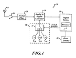
- FIGURE 1 is a block diagram of a system 20 formed in accordance with an embodiment of the invention.
- the system 20 includes an antenna 22 in signal communication with an amplifier 24.
- the amplifier 24 is in signal communication with an input of an analog filter 26.
- An output of the filter 26 is in signal communication with an input of an analog to digital converter (ADC) 28.
- ADC 28 is in signal communication with a digital system 30 that includes at least a processor 31.
- a sampling rate of the ADC 28 is driven by a clock signal generator 32 that is in signal communication with a clock input of the ADC 28.
- the clock signal generator 32 includes a switch 34 that is in signal communication with and controlled by the digital system 30.
- a first oscillator clock 36 having a first frequency Fs1, a second oscillator clock 38 having a second frequency Fs2, and a third oscillator clock 40 having a third frequency Fs3 are each in signal communication with the switch 34.
- the switch 34 is configured to selectively connect an output of one of the oscillator clocks 36, 38, 40 to the clock input of the ADC 28.
- the system 20 is in signal communication with other external systems 42 so that information may be passed between the digital system 30 and the external systems 42.
- the system 20 receives a signal at the antenna 22, amplifies the signal at the amplifier 24, and filters the amplified signal at the filter 26.
- the ADC 28 samples the amplified, filtered input signal using a sample rate determined by the digital system 30 and the sample clock generator 32.
- the filter 26 is configured to pass at least two Nyquist bands of a signal sampled by the ADC 28.
- the sampled signal passes to the digital system 30, where the processor 31 is configured to identify a predetermined desired signal, determine whether a possible interfering signal exists at a next sampling rate selected from the plurality of sampling rates using the currently selected sampling rate, and instruct the clock signal generator 32 to generate the next sampling rate if the processor 31 determines that a possible interfering signal does not exist.
- identifying a predetermined desired signal includes extracting information from a portion of the sampled signal. If the processor 31 determines that a possible interfering signal does exist, the processor 31 is configured to determine whether a possible interfering signal exists at each of the other sampling rates selected from the plurality of sampling rates using the currently selected sampling rate until a sampling rate is found that does not have a possible interfering signal, and instruct the clock signal generator 32 to generate the sampling rate that was determined to not have a possible interfering signal, if the processor 31 determines that such a sampling rate exists. In an example, the processor 31 is generally configured to repetitively perform the preceding steps.
- the system 20 is a distance measuring equipment (DME) system for detecting a DME signal across multiple Nyquist bands.
- the processor 31 is configured to identify a predetermined desired DME signal.
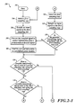
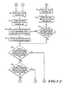
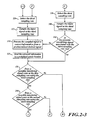
- FIGURES 2-1 through 2-3 are flowcharts of an example method 100 of detecting a signal in accordance with an embodiment of the invention.
- a start block 102 indicates a point at which the method 100 begins in an example embodiment.
- a first sampling rate is selected. This might be a sampling rate corresponding to a frequency of Fs1 from the first oscillator clock 36 shown in FIGURE 1 , for example.
- an input signal is sampled at the first sampling rate.
- the input signal is the signal output from the filter 26 and is sampled by the ADC 28.
- the sampled signal is processed by the processor 31 to extract information from a predetermined desired portion of the sampled input signal, such as a desired signal, for example.
- the predetermined desired portion may be a digitally modulated channel, an analog modulated channel, or a particular pulse pattern at a given channel frequency, for example.
- the processor 31 performs the sampled signal processing.
- the extracted information is sent to a predefined system location for further processing and/or output.
- the predefined system location may be a component of the digital system 30 or one or more of the other systems 42, for example.
- the processor 31 determines whether a possible signal that interferes with the desired portion exists at a second sampling rate using the first sampling rate.
- the second sampling rate corresponds to a frequency of Fs2 from the second oscillator clock 38 shown in FIGURE 1 and the processor 31 is configured to determine whether the possible interfering signal exists.
- the method 100 proceeds to a block 112 shown on FIGURE 2-2 where the second sampling rate is selected.
- the second sampling rate is selected by the processor 31 directing the switch 34 to change from the first oscillator clock 36 at frequency Fs1 to the second oscillator clock 38 at frequency Fs2 as an output to the ADC 28.
- the input signal is sampled at the second sampling rate.
- the sampled signal is processed by the processor 31 to extract information from a predetermined desired portion of the sampled input signal.
- the extracted information is sent to a predefined system location for further processing and/or output.
- the predefined system location may be a component of the digital system 30 or one or more of the other systems 42, for example.
- the processor 31 determines whether a possible signal that interferes with the desired portion exists at a third sampling rate using the second sampling rate.
- the third sampling rate corresponds to a frequency of Fs3 from the third oscillator clock 40 shown in FIGURE 1 and the processor 31 is configured to determine whether the possible interfering signal exists.
- the method 100 proceeds to a block 120 shown on FIGURE 2-3 where the third sampling rate is selected.
- the third sampling rate is selected by the processor 31 directing the switch 34 to change from the second oscillator clock 38 at frequency Fs2 to the third oscillator clock 40 at frequency Fs3 as an output to the ADC 28.
- the input signal is sampled at the third sampling rate.
- the sampled signal is processed by the processor 31 to extract information from a predetermined desired portion of the sampled input signal, such as a desired signal for example.
- the extracted information is sent to a predefined system location for further processing and/or output.
- the predefined system location may be a component of the digital system 30 or one or more of the other systems 42, for example.
- the processor 31 determines whether a possible signal that interferes with the desired portion exists at the first sampling rate using the third sampling rate. In an example, the processor 31 is configured to determine whether the possible interfering signal exists. If, at the decision block 126, the processor 31 determines that an interfering signal does not exist at the first sampling rate, the method 100 returns to the block 104 shown on FIGURE 2-1 as indicated by a connector D.
- the method 100 proceeds to a decision block 128 where the processor 31 determines whether a possible signal that interferes with the desired portion exists at the third sampling rate using the first sampling rate. If the processor 31 determines at the decision block 128 that the possible interfering signal does not exist at the third sampling rate, the method 100 proceeds to the block 120 shown on FIGURE 2-3 as indicated by a connector F.
- the method 100 proceeds to a block 130 shown on FIGURE 2-2 , as indicated by a connector B, where the second sampling rate is selected in similar fashion to that described with respect to the block 112.
- the input signal is sampled at the second sampling rate.
- the processor 31 determines whether the possible interfering signal is real.
- the processor 31 is configured to perform the determination at the decision block 134 by determining whether an amount of energy associated with the possible interfering signal using the first sampling rate as determined by the processor 31 in the decision block 110 has moved to a non-interfering signal using the second sampling rate. If the energy associated with the possible interfering signal has moved to a non-interfering signal, the processor 31 determines that the possible interfering signal is not real. If the energy associated with the interfering signal is still associated with an interfering signal, the processor 31 determines that the possible interfering signal is real. If the processor 31 determines that the possible interfering signal is not real, the method 100 proceeds to the block 116. If the processor 31 determines that the possible interfering signal is real, the method 100 proceeds to the block decision 118.
- the method 100 proceeds to a decision block 136 where the processor 31 determines whether a possible signal that interferes with the desired portion exists at the first sampling rate using the second sampling rate. If the processor 31 determines at the decision block 136 that the possible interfering signal does not exist at the first sampling rate, the method 100 proceeds to the block 104 shown on FIGURE 2-1 as indicated by a connector D. If the processor 31 determines at the decision block 136 that the possible interfering signal exists at the first sampling rate, the method 100 proceeds to a block 138 shown on FIGURE 2-3 , as indicated by a connector C, where the third sampling rate is selected in similar fashion to that described with respect to the block 120. Next, at a block 140, the input signal is sampled at the third sampling rate. Next, at a decision block 142, the processor 31 determines whether the possible interfering signal is real.
- the processor 31 is configured to perform the determination at the decision block 142 by determining whether an amount of energy associated with the possible interfering signal using the second sampling rate as determined in the decision block 118 has moved to a non-interfering signal using the third sampling rate. If the energy associated with the possible interfering signal has moved to a non-interfering signal, the processor 31 determines that the possible interfering signal is not real. If the energy associated with the interfering signal is still associated with an interfering signal, the processor 31 determines that the possible interfering signal is real. If the processor 31 determines that the possible interfering signal is not real, the method 100 proceeds to the block 124. If the processor 31 determines that the possible interfering signal is real, the method 100 proceeds to the decision block 126.
- the method 100 proceeds to a decision block 144 where the processor 31 determines whether a possible signal that interferes with the desired portion exists at the second sampling rate using the third sampling rate. If the processor 31 determines at the decision block 144 that the possible interfering signal does not exist at the second sampling rate, the method 100 proceeds to the block 112 shown on FIGURE 2-2 as indicated by a connector E.
- the method 100 proceeds to a block 146 shown on FIGURE 2-1 , as indicated by a connector A, where the first sampling rate is selected in similar fashion to that described with respect to the block 104.
- the input signal is sampled at the first sampling rate.
- the processor 31 determines whether the possible interfering signal is real.
- the processor 31 is configured to perform the determination at the decision block 150 by determining whether an amount of energy associated with the possible interfering signal using the third sampling rate as determined in the decision block 126 has moved to a non-interfering signal using the first sampling rate. If the energy associated with the possible interfering signal has moved to a non-interfering signal, the processor 31 determines that the possible interfering signal is not real. If the energy associated with the interfering signal is still associated with an interfering signal, the processor 31 determines that the possible interfering signal is real. If the processor 31 determines that the possible interfering signal is not real, the method 100 proceeds to the block 108. If the processor 31 determines that the possible interfering signal is real, the method 100 proceeds to the decision block 110.
- the first sampling rate Fs1 may be selected at the block 104 shown on FIGURE 2-1 to be 100 MHz and the predetermined desired signal may be 60 MHz. With a sampling rate based on 100 MHz, a desired signal of 60 MHz is within a second Nyquist band. Since the sampling rate is only 100 mega samples per second (MSPS), which is the sampling rate corresponding to 100 MHz, the desired signal of 60 MHz is identified by looking for its alias at 40 MHz in a first Nyquist band during the processing that occurs at the block 108. In this example, the second sampling frequency Fs2 may be 101 MHz with a resulting 101 MSPS rate.
- MSPS mega samples per second
- the processor 31 determines whether a possible interfering signal exists at the 101 MSPS rate while using the 100 MSPS rate.
- An alias of the desired 60 MHz signal while sampling at 101 MSPS would be 41 MHz. While sampling at 100 MSPS, a 41 MHz signal may be an alias of a 59 MHz signal. So, at the decision block 110, the processor 31 determines whether a possible interfering signal exists by looking for the signal at 41 MHz while sampling at 100 MSPS.
- the processor 31 determines that a possible interfering signal at 41 MHz does not exist, the Fs2 frequency of 101 MHz is used for a 101 MSPS sampling rate. The processor 31 then determines at the block 116 shown on FIGURE 2-2 whether the desired 60 MHz signal is present by looking for its alias at 41 MHz. In this example, the third sampling frequency Fs3 may be 102.5 MHz with a corresponding 102.5 MSPS sampling rate. At the decision block 118, the processor 31 determines whether a possible interfering signal exists at the 102.5 MSPS rate while using the 101 MSPS rate. An alias of the desired 60 MHz signal while sampling at 102.5 MHz would be 42.5 MHz.
- a 42.5 MHz signal may be an alias of a 58.5 MHz signal. So, at the decision block 118, the processor 31 determines whether a possible interfering signal exists by looking for the signal at 42.5 MHz while sampling at 101 MHz.
- the processor 31 determines that a possible interfering signal at 42.5 MHz does not exist, the Fs3 frequency of 102.5 MHz is used for a 102.5 MSPS sampling rate.
- the processor 31 determines whether the desired 60 MHz signal is present by looking for its alias at 42.5 MHz.
- the processor 31 determines whether a possible interfering signal exists at the 100 MSPS rate while using the 102.5 MSPS rate. The processor 31 determines whether a possible interfering signal exists by looking for the signal at 40 MHz while sampling at 102.5 MHz. If the processor 31 determines that the possible interfering signal does not exist, the method 100 returns to the block 104 shown on FIGURE 2-1 .
- the method 100 proceeds to the decision blocks 128, 136, or 144 respectively. Determinations at the decision blocks 128, 136, and 144 are made in similar fashion to those at the decision blocks 110, 118, and 126.
- a 100 MSPS rate is used to look for a signal at 42.5 MHz.
- a 101 MSPS rate is used to look for a signal at 40 MHz.
- a 102.5 MSPS rate is used to look for a signal at 41 MHz.
- the processor 31 determines whether the possible interfering signal has moved to another frequency at the decision blocks 134, 142, or 150 respectively to determine whether the possible interfering signal is real.
- an energy level associated with the possible interfering signal found during the determination performed at the decision blocks 110, 118, or 126 is stored so that the stored energy level can be compared to energy levels of signals detected after sampling with the new sampling rate at the block 132, 140, or 148. So, if an energy of 1 milliwatt (mW) is detected at 41 MHz during the determination performed at the decision block 110 and a possible interfering signal also found at the decision block 128, the determination performed at the decision block 134 looks at the energy of any detected signal at 42 MHz because if the 41 MHz signal that was seen using the 100 MSPS rate came from the second Nyquist band, the 41 MHz signal would have come from an alias of a 59 MHz signal.
- mW milliwatt
- the processor 31 determines that it is the same energy that was seen at 41 MHz using the 100 MSPS rate and the processor 31 determines that the possible interferer is not real and the method 100 proceeds to the block 116. If, on the other hand, the amount of energy at 42 MHz is much less than 1 mW at the 101 MSPS rate, the processor 31 determines that what looked like 41 MHz at the 100 MSPS rate was actually coming from a signal at 41 MHz and that the energy is now aliased onto the desired channel. The processor 31 determines that the possible interferer is real and the method 100 proceeds to the decision block 118.
- the determinations performed at the decision blocks 142 and 150 proceed in similar fashion to that described with respect to the decision block 134.
- an energy measurement for a possible interfering signal was stored for the determination performed at the decision blocks 110, 118, and 126
- the energy measurement may be stored for the determination performed at the decision blocks 128, 136, and 144, with a different next sampling rate if the processor 31 determines that a possible interferer exists.
- a desired signal and possible interfering signals may exist in other Nyquist bands.
- a desired signal may be in the first Nyquist band while interfering signals are aliases in the second Nyquist band.
- the system may search for (total Nyquist bands - 1) possible alias interferers per desired channel, for example. Differing numbers of sample rates may also be used, and the particular ordering of steps shown for the method may vary. Additionally, some of the method steps may be performed in parallel and the system may be configured to dwell for predetermined periods of time after performing some method steps. Accordingly, the scope of the invention is not limited by the disclosure of the preferred embodiment. Instead, the invention should be determined entirely by reference to the claims that follow.
Landscapes
- Engineering & Computer Science (AREA)
- Radar, Positioning & Navigation (AREA)
- Remote Sensing (AREA)
- Computer Networks & Wireless Communication (AREA)
- Physics & Mathematics (AREA)
- General Physics & Mathematics (AREA)
- Theoretical Computer Science (AREA)
- Analogue/Digital Conversion (AREA)
- Noise Elimination (AREA)
Applications Claiming Priority (1)
| Application Number | Priority Date | Filing Date | Title |
|---|---|---|---|
| US12/026,479 US8064560B2 (en) | 2008-02-05 | 2008-02-05 | Systems and methods for detecting a signal across multiple Nyquist bands |
Publications (3)
| Publication Number | Publication Date |
|---|---|
| EP2088676A2 true EP2088676A2 (de) | 2009-08-12 |
| EP2088676A3 EP2088676A3 (de) | 2010-04-28 |
| EP2088676B1 EP2088676B1 (de) | 2012-02-29 |
Family
ID=40589795
Family Applications (1)
| Application Number | Title | Priority Date | Filing Date |
|---|---|---|---|
| EP09151474A Active EP2088676B1 (de) | 2008-02-05 | 2009-01-27 | Systeme und Verfahren zum Erkennen eines Signals über mehreren NYQUIST-Bänder |
Country Status (2)
| Country | Link |
|---|---|
| US (1) | US8064560B2 (de) |
| EP (1) | EP2088676B1 (de) |
Cited By (1)
| Publication number | Priority date | Publication date | Assignee | Title |
|---|---|---|---|---|
| WO2017001576A1 (de) * | 2015-06-30 | 2017-01-05 | TRUMPF Hüttinger GmbH + Co. KG | Verfahren zum abtasten eines mit einem plasmaprozess in beziehung stehenden signalgemischs |
Families Citing this family (7)
| Publication number | Priority date | Publication date | Assignee | Title |
|---|---|---|---|---|
| US9448964B2 (en) * | 2009-05-04 | 2016-09-20 | Cypress Semiconductor Corporation | Autonomous control in a programmable system |
| US9577855B1 (en) | 2011-07-13 | 2017-02-21 | Softronics, Ltd. | Channelized multicarrier digitizer |
| US9614629B2 (en) | 2012-08-15 | 2017-04-04 | Commscope Technologies Llc | Telecommunication system using multiple Nyquist zone operations |
| KR102033077B1 (ko) * | 2013-08-07 | 2019-10-16 | 나이키 이노베이트 씨.브이. | 제스처 인식 및 전력 관리를 갖는 손목 착용 운동 디바이스 |
| CN105874717B (zh) * | 2014-01-15 | 2018-02-23 | 安娜卡敦设计公司 | 认知信号转换器 |
| US9559714B2 (en) * | 2015-04-24 | 2017-01-31 | The Board Of Trustees Of The Leland Stanford Junior University | Analog-to-digital compression |
| KR102457566B1 (ko) * | 2018-02-22 | 2022-10-21 | 한국전자통신연구원 | 데이터 패킷의 버스트의 길이에 기초하여 변복조를 수행하는 변복조기 및 상기 복조기가 수행하는 방법 |
Family Cites Families (19)
| Publication number | Priority date | Publication date | Assignee | Title |
|---|---|---|---|---|
| IT1123407B (it) | 1979-10-02 | 1986-04-30 | Face Standard Ind | Impianto di misura di distanza per aeronavigazione di prescisione |
| US4893266A (en) | 1987-06-01 | 1990-01-09 | Motorola, Inc. | Alias tagging time domain to frequency domain signal converter |
| JP2975041B2 (ja) * | 1990-03-27 | 1999-11-10 | 株式会社日立製作所 | ディジタル信号処理プロセッサ |
| US5099243A (en) | 1991-03-06 | 1992-03-24 | The United States Of America As Represented By The Secretary Of The Air Force | Digital frequency measurement receiver with bandwidth improvement through multiple sampling of complex signals |
| US5109188A (en) | 1991-03-06 | 1992-04-28 | The United States Of America As Represented By The Secretary Of The Air Force | Instantaneous frequency measurement receiver with bandwidth improvement through phase shifted sampling of real signals |
| US5099194A (en) | 1991-03-06 | 1992-03-24 | The United States Of America As Represented By The Secretary Of The Air Force | Digital frequency measurement receiver with bandwidth improvement through multiple sampling of real signals |
| US5198748A (en) | 1991-10-28 | 1993-03-30 | The United States Of America As Represented By The Secretary Of The Air Force | Frequency measurement receiver with bandwidth improvement through synchronized phase shifted sampling |
| US5874914A (en) | 1995-10-09 | 1999-02-23 | Snaptrack, Inc. | GPS receiver utilizing a communication link |
| US5815101A (en) | 1996-08-02 | 1998-09-29 | Fonte; Gerard C. A. | Method and system for removing and/or measuring aliased signals |
| US6031869A (en) | 1996-10-21 | 2000-02-29 | Texas Instruments Incorporated | Use of multiple sample frequencies to resolve ambiguities in band-folded digital receivers |
| US6026418A (en) | 1996-10-28 | 2000-02-15 | Mcdonnell Douglas Corporation | Frequency measurement method and associated apparatus |
| US6337885B1 (en) | 1998-02-13 | 2002-01-08 | Telefonaktiebolaget Lm Ericsson (Publ) | Radio receiver that digitizes a received signal at a plurality of digitization frequencies |
| US6301545B1 (en) | 1999-04-30 | 2001-10-09 | Sirf Technology, Inc. | Global positioning system tag system |
| GB2349783A (en) | 1999-05-07 | 2000-11-08 | Oak Technology Inc | Receiver circuit using sub sampling analogue to digital converter to frequency shift the signal |
| FI113819B (fi) | 2000-10-17 | 2004-06-15 | Nokia Corp | Menetelmä radiotaajuisen signaalin vastaanottamiseksi ja vastaanotinlaite |
| US20060227898A1 (en) | 2003-07-10 | 2006-10-12 | Gibson Timothy P | Radio receiver |
| US8102954B2 (en) * | 2005-04-26 | 2012-01-24 | Mks Instruments, Inc. | Frequency interference detection and correction |
| WO2007047248A2 (en) | 2005-10-11 | 2007-04-26 | L-3 Communications Integrated Systems L.P. | Nyquist folded bandpass sampling receivers and related methods |
| US7498966B2 (en) | 2006-12-14 | 2009-03-03 | Honeywell International Inc. | Method and system for receiving distance measurement equipment channels in an undersampled broadband receiver |
-
2008
- 2008-02-05 US US12/026,479 patent/US8064560B2/en active Active
-
2009
- 2009-01-27 EP EP09151474A patent/EP2088676B1/de active Active
Cited By (1)
| Publication number | Priority date | Publication date | Assignee | Title |
|---|---|---|---|---|
| WO2017001576A1 (de) * | 2015-06-30 | 2017-01-05 | TRUMPF Hüttinger GmbH + Co. KG | Verfahren zum abtasten eines mit einem plasmaprozess in beziehung stehenden signalgemischs |
Also Published As
| Publication number | Publication date |
|---|---|
| US8064560B2 (en) | 2011-11-22 |
| US20090196385A1 (en) | 2009-08-06 |
| EP2088676A3 (de) | 2010-04-28 |
| EP2088676B1 (de) | 2012-02-29 |
Similar Documents
| Publication | Publication Date | Title |
|---|---|---|
| EP2088676B1 (de) | Systeme und Verfahren zum Erkennen eines Signals über mehreren NYQUIST-Bänder | |
| US8849213B2 (en) | Integrated circuit for signal analysis | |
| US7151790B1 (en) | Automatic signal extraction and analysis from time-frequency representation | |
| JP6026531B2 (ja) | レーダー用デジタル受信機を用いるレーダーパルス検出 | |
| CA2472319C (en) | Detecting and measuring interference contained within a digital carrier | |
| EP1672376B1 (de) | RF/IF-Signaturauslösung in Echtzeit | |
| EP2219039B1 (de) | Amplitudenunterscheidung mittels des Frequenzmaskenauslösers | |
| EP1976129B1 (de) | Verfahren zur Bearbeitung eines von einem analogen Eingangssignal eines GNSS-Empfängers abgeleiteten digitalen Signals, Basisbandschaltung eines GNSS-Empfängers zur Durchführung des Verfahrens und GNSS-Empfänger | |
| US20120083218A1 (en) | System and method for collaborative spectrum analysis | |
| KR20180116186A (ko) | 우세 신호 검출 방법 및 장치 | |
| EP1745559A1 (de) | Empfänger zur löschung von schmalbandigen störungen | |
| CN110988473B (zh) | 宽带突发信号频谱分析仪及宽带突发信号分析方法 | |
| EP2204914B1 (de) | Verfahren zur Verarbeitung eines aus einem Direktsequenz-Spreizspektrum-Signals abgeleitetem digitalen Signals | |
| US8831078B2 (en) | Method and device for identifying at least one communication channel with an incident signal | |
| CN104969562B (zh) | 用于确定占用信道的测量设备和测量方法 | |
| EP2282220A1 (de) | Spektrumanalyse | |
| CN105116220B (zh) | 同步分离信号与噪声的信号分析装置及其分析方法 | |
| JP2009180540A (ja) | パルス諸元検出装置 | |
| KR101873798B1 (ko) | 미상의 주파수도약신호에 대한 실시간 도약정보 생성장치 및 그 방법 | |
| KR102000188B1 (ko) | 다채널 통신신호 탐지를 통한 통신정보 생성 장치 | |
| CN102196536B (zh) | 一种利用基站实现信号扫描和分析的方法 | |
| JP4449615B2 (ja) | 受信モニタ装置及び受信モニタ方法 | |
| RU2763583C2 (ru) | Способ определения частоты в приемнике с субдискретизацией | |
| CN105207962B (zh) | 一种高频率精度的干扰信号搜索方法 | |
| US7941114B2 (en) | Noise measurement for radio squelch function |
Legal Events
| Date | Code | Title | Description |
|---|---|---|---|
| PUAI | Public reference made under article 153(3) epc to a published international application that has entered the european phase |
Free format text: ORIGINAL CODE: 0009012 |
|
| 17P | Request for examination filed |
Effective date: 20090127 |
|
| AK | Designated contracting states |
Kind code of ref document: A2 Designated state(s): AT BE BG CH CY CZ DE DK EE ES FI FR GB GR HR HU IE IS IT LI LT LU LV MC MK MT NL NO PL PT RO SE SI SK TR |
|
| AX | Request for extension of the european patent |
Extension state: AL BA RS |
|
| PUAL | Search report despatched |
Free format text: ORIGINAL CODE: 0009013 |
|
| AK | Designated contracting states |
Kind code of ref document: A3 Designated state(s): AT BE BG CH CY CZ DE DK EE ES FI FR GB GR HR HU IE IS IT LI LT LU LV MC MK MT NL NO PL PT RO SE SI SK TR |
|
| AX | Request for extension of the european patent |
Extension state: AL BA RS |
|
| RIC1 | Information provided on ipc code assigned before grant |
Ipc: G01S 7/40 20060101ALI20100325BHEP Ipc: H03M 1/12 20060101AFI20090508BHEP Ipc: G01S 13/78 20060101ALI20100325BHEP |
|
| AKX | Designation fees paid |
Designated state(s): DE |
|
| GRAP | Despatch of communication of intention to grant a patent |
Free format text: ORIGINAL CODE: EPIDOSNIGR1 |
|
| RIC1 | Information provided on ipc code assigned before grant |
Ipc: H03M 1/12 20060101AFI20110221BHEP Ipc: G01S 7/40 20060101ALI20110221BHEP Ipc: G01S 13/78 20060101ALI20110221BHEP |
|
| GRAS | Grant fee paid |
Free format text: ORIGINAL CODE: EPIDOSNIGR3 |
|
| GRAL | Information related to payment of fee for publishing/printing deleted |
Free format text: ORIGINAL CODE: EPIDOSDIGR3 |
|
| GRAS | Grant fee paid |
Free format text: ORIGINAL CODE: EPIDOSNIGR3 |
|
| GRAL | Information related to payment of fee for publishing/printing deleted |
Free format text: ORIGINAL CODE: EPIDOSDIGR3 |
|
| GRAS | Grant fee paid |
Free format text: ORIGINAL CODE: EPIDOSNIGR3 |
|
| GRAL | Information related to payment of fee for publishing/printing deleted |
Free format text: ORIGINAL CODE: EPIDOSDIGR3 |
|
| GRAS | Grant fee paid |
Free format text: ORIGINAL CODE: EPIDOSNIGR3 |
|
| GRAA | (expected) grant |
Free format text: ORIGINAL CODE: 0009210 |
|
| AK | Designated contracting states |
Kind code of ref document: B1 Designated state(s): DE |
|
| REG | Reference to a national code |
Ref country code: DE Ref legal event code: R096 Ref document number: 602009005571 Country of ref document: DE Effective date: 20120426 |
|
| PLBE | No opposition filed within time limit |
Free format text: ORIGINAL CODE: 0009261 |
|
| STAA | Information on the status of an ep patent application or granted ep patent |
Free format text: STATUS: NO OPPOSITION FILED WITHIN TIME LIMIT |
|
| 26N | No opposition filed |
Effective date: 20121130 |
|
| REG | Reference to a national code |
Ref country code: DE Ref legal event code: R097 Ref document number: 602009005571 Country of ref document: DE Effective date: 20121130 |
|
| P01 | Opt-out of the competence of the unified patent court (upc) registered |
Effective date: 20230525 |
|
| PGFP | Annual fee paid to national office [announced via postgrant information from national office to epo] |
Ref country code: DE Payment date: 20260127 Year of fee payment: 18 |