EP2088706A2 - Format de données pour économiser de l'énergie dans un module de communication - Google Patents
Format de données pour économiser de l'énergie dans un module de communication Download PDFInfo
- Publication number
- EP2088706A2 EP2088706A2 EP09162282A EP09162282A EP2088706A2 EP 2088706 A2 EP2088706 A2 EP 2088706A2 EP 09162282 A EP09162282 A EP 09162282A EP 09162282 A EP09162282 A EP 09162282A EP 2088706 A2 EP2088706 A2 EP 2088706A2
- Authority
- EP
- European Patent Office
- Prior art keywords
- data
- format
- meter
- signature
- field
- Prior art date
- Legal status (The legal status is an assumption and is not a legal conclusion. Google has not performed a legal analysis and makes no representation as to the accuracy of the status listed.)
- Withdrawn
Links
- 238000004891 communication Methods 0.000 title claims description 45
- 125000004122 cyclic group Chemical group 0.000 claims abstract description 10
- 230000005540 biological transmission Effects 0.000 claims description 16
- 238000000034 method Methods 0.000 claims description 7
- 101000651958 Crotalus durissus terrificus Snaclec crotocetin-1 Proteins 0.000 claims description 6
- 238000001816 cooling Methods 0.000 claims description 2
- 230000005611 electricity Effects 0.000 claims description 2
- 238000010438 heat treatment Methods 0.000 claims description 2
- XLYOFNOQVPJJNP-UHFFFAOYSA-N water Substances O XLYOFNOQVPJJNP-UHFFFAOYSA-N 0.000 claims description 2
- 101100524585 Arabidopsis thaliana RH14 gene Proteins 0.000 description 6
- 230000009977 dual effect Effects 0.000 description 4
- 230000035945 sensitivity Effects 0.000 description 4
- 101100258328 Neurospora crassa (strain ATCC 24698 / 74-OR23-1A / CBS 708.71 / DSM 1257 / FGSC 987) crc-2 gene Proteins 0.000 description 3
- 238000009434 installation Methods 0.000 description 3
- 238000012795 verification Methods 0.000 description 3
- 239000000203 mixture Substances 0.000 description 2
- 230000002457 bidirectional effect Effects 0.000 description 1
- 230000000903 blocking effect Effects 0.000 description 1
- 230000003111 delayed effect Effects 0.000 description 1
- 239000000945 filler Substances 0.000 description 1
- 230000002035 prolonged effect Effects 0.000 description 1
- 230000003068 static effect Effects 0.000 description 1
Images


Classifications
-
- H—ELECTRICITY
- H04—ELECTRIC COMMUNICATION TECHNIQUE
- H04L—TRANSMISSION OF DIGITAL INFORMATION, e.g. TELEGRAPHIC COMMUNICATION
- H04L1/00—Arrangements for detecting or preventing errors in the information received
- H04L1/0001—Systems modifying transmission characteristics according to link quality, e.g. power backoff
- H04L1/0023—Systems modifying transmission characteristics according to link quality, e.g. power backoff characterised by the signalling
- H04L1/0028—Formatting
- H04L1/0029—Reduction of the amount of signalling, e.g. retention of useful signalling or differential signalling
-
- G—PHYSICS
- G01—MEASURING; TESTING
- G01D—MEASURING NOT SPECIALLY ADAPTED FOR A SPECIFIC VARIABLE; ARRANGEMENTS FOR MEASURING TWO OR MORE VARIABLES NOT COVERED IN A SINGLE OTHER SUBCLASS; TARIFF METERING APPARATUS; MEASURING OR TESTING NOT OTHERWISE PROVIDED FOR
- G01D4/00—Tariff metering apparatus
- G01D4/002—Remote reading of utility meters
-
- H—ELECTRICITY
- H04—ELECTRIC COMMUNICATION TECHNIQUE
- H04L—TRANSMISSION OF DIGITAL INFORMATION, e.g. TELEGRAPHIC COMMUNICATION
- H04L1/00—Arrangements for detecting or preventing errors in the information received
- H04L1/004—Arrangements for detecting or preventing errors in the information received by using forward error control
- H04L1/0056—Systems characterized by the type of code used
- H04L1/0061—Error detection codes
-
- H—ELECTRICITY
- H04—ELECTRIC COMMUNICATION TECHNIQUE
- H04L—TRANSMISSION OF DIGITAL INFORMATION, e.g. TELEGRAPHIC COMMUNICATION
- H04L1/00—Arrangements for detecting or preventing errors in the information received
- H04L1/0078—Avoidance of errors by organising the transmitted data in a format specifically designed to deal with errors, e.g. location
- H04L1/0083—Formatting with frames or packets; Protocol or part of protocol for error control
-
- H—ELECTRICITY
- H04—ELECTRIC COMMUNICATION TECHNIQUE
- H04L—TRANSMISSION OF DIGITAL INFORMATION, e.g. TELEGRAPHIC COMMUNICATION
- H04L1/00—Arrangements for detecting or preventing errors in the information received
- H04L1/0078—Avoidance of errors by organising the transmitted data in a format specifically designed to deal with errors, e.g. location
- H04L1/0091—Avoidance of errors by organising the transmitted data in a format specifically designed to deal with errors, e.g. location arrangements specific to receivers, e.g. format detection
-
- Y—GENERAL TAGGING OF NEW TECHNOLOGICAL DEVELOPMENTS; GENERAL TAGGING OF CROSS-SECTIONAL TECHNOLOGIES SPANNING OVER SEVERAL SECTIONS OF THE IPC; TECHNICAL SUBJECTS COVERED BY FORMER USPC CROSS-REFERENCE ART COLLECTIONS [XRACs] AND DIGESTS
- Y02—TECHNOLOGIES OR APPLICATIONS FOR MITIGATION OR ADAPTATION AGAINST CLIMATE CHANGE
- Y02B—CLIMATE CHANGE MITIGATION TECHNOLOGIES RELATED TO BUILDINGS, e.g. HOUSING, HOUSE APPLIANCES OR RELATED END-USER APPLICATIONS
- Y02B90/00—Enabling technologies or technologies with a potential or indirect contribution to GHG emissions mitigation
- Y02B90/20—Smart grids as enabling technology in buildings sector
-
- Y—GENERAL TAGGING OF NEW TECHNOLOGICAL DEVELOPMENTS; GENERAL TAGGING OF CROSS-SECTIONAL TECHNOLOGIES SPANNING OVER SEVERAL SECTIONS OF THE IPC; TECHNICAL SUBJECTS COVERED BY FORMER USPC CROSS-REFERENCE ART COLLECTIONS [XRACs] AND DIGESTS
- Y04—INFORMATION OR COMMUNICATION TECHNOLOGIES HAVING AN IMPACT ON OTHER TECHNOLOGY AREAS
- Y04S—SYSTEMS INTEGRATING TECHNOLOGIES RELATED TO POWER NETWORK OPERATION, COMMUNICATION OR INFORMATION TECHNOLOGIES FOR IMPROVING THE ELECTRICAL POWER GENERATION, TRANSMISSION, DISTRIBUTION, MANAGEMENT OR USAGE, i.e. SMART GRIDS
- Y04S20/00—Management or operation of end-user stationary applications or the last stages of power distribution; Controlling, monitoring or operating thereof
- Y04S20/30—Smart metering, e.g. specially adapted for remote reading
Definitions
- the invention relates to a data format suited for transmitting data from a communication module in a power efficient manner.
- the invention can be applied in a communication module for a consumption meter so as to allow power efficient automatic reading of a consumed quantity.
- the invention is particularly suited for battery operated meters communicating data using the MBUS protocol (EN 13757-3), but the invention can also be utilized on other protocols, such as COSEM or DLMS.
- Consumption meters with communication modules for automatic reading purposes e.g. wireless Radio Frequency (RF) modules
- RF Radio Frequency
- a wireless RF communication module is often the only electronic part in such a meter, or for fully electronic meters it is often the most power demanding component, and thus the operation of such communication module significantly influences battery life time of the meter. This is especially the case if it is required that the meter continuously transmits read values, such as with intervals of a few seconds, which is required to allow predictable and efficient drive-by reading of the meter.
- one communication session between a consumption meter and a reading system includes transmitting a packet of one or more frames from the consumption meter, and optionally the reading system transmits a response to which the consumption meter finally transmits a reply frame.
- the relatively simple data in the form of a quantity value and a time or reading often represent a small fraction of the bits required in a full MBUS string.
- the length of such as header and format information in such MBUS string is significant compared to the number of data bits itself.
- a significant amount of electrical power consumed by the communication module is due to transmitting bits which do not directly represent the essential data values.
- the data format will most often be the same, and thus power is lost for transmitting redundant information.
- an object of the present invention to provide an improved data format allowing power efficient transmission of data from a device, such as a consumption meter with a battery driven communication module.
- the invention provides a data format for communicating data, the data format comprising a data packet comprising
- a receiver By including such signature representing coded information regarding a format of the data field, it is possible for a receiver to combine with the identification of the device in order to get information of the format of the data field. This can be done with a signature having a length of a few bits, e.g. by the receiver having a pre-stored table of device identifications and signatures indicating the various data field formats available for a number of devices. Compared to transmitting e.g. a full MBUS string (according to EN 13757-3) with the data field format in each data packet, a substantial amount of electric power can be saved in the device when transmitting many data packet having the same data field format.
- the invention provides a device comprising a communication module, such as a wireless Radio Frequency transmitter, arranged to transmit a data format according to the first aspect.
- a communication module such as a wireless Radio Frequency transmitter
- such device is capable of saving electric power for its communication module, since redundant data field format information is eliminated. This is a significant improvement especially for battery driven devices which are required to transmit many data packets, leading to a prolonged battery life time.
- the device may either comprise a plurality of different pre-stored signatures linked to different data field formats, such as different decimal places for the data representing the quantity value, or such as different types of data represented in the data field, or the device may be arranged to compute a signature according to a format of the data in the data field.
- the device may include only a few, e.g. two or three, different pre-stored signatures which can then be selected corresponding to the same number of possible data field formats.
- a large number of possible data field formats may exist, including mixtures of number formats and types of data.
- the device computes the signature according to the actual data field format.
- the signature has a very limited length in order to save the most power.
- a signature length of less than 30 bits, e.g. a length of 16 bits, is found suitable for automatic reading of consumption meters.
- the signature may represent a check sum, such as a Cyclic Redundancy Check sum of the information regarding the format of the data field.
- the device may have a plurality of communication modes comprising: a pure transmission mode, and a bi-directional mode.
- a pure transmission modem the communication module may repeatedly transmit data packets, such as transmitting a data packet with an intermediate interval of 1-60 seconds, such as an intermediate interval of 5-20 seconds.
- the device, or at least the communication module of the device may be driven by a battery.
- the power saving data packet format it is possible to have a long life of the battery even in case of frequent data packet transmissions, such as a communication module continuously transmitting data packets with intervals of a few seconds.
- the communication module may comprise an RF transmitter arranged to transmit the data packet in an RF representation, such as at a carrier frequency within 860-880 MHz, such as using a Gaussian Frequency-Shift Keying modulation.
- the communication module may be arranged for transmitting the data packet in a communication medium being one of: air, a dedicated wired medium, and a public electric supply network.
- the device is a consumption meter, such as a charging consumption meter, arranged to measure a quantity of a physical entity and to generate a quantity value accordingly, and wherein the data in the data field comprises data representing a time where the consumption meter has measured the consumed quantity and data representing the quantity value.
- the invention is especially suited for battery driven consumption meters having a mode of transmission where data packets with data representing quantity data and corresponding reading time are transmitted continuously with intervals of a few seconds.
- the consumption meter may be an electricity meter, a heating meter, a cooling meter, a water meter, or a gas meter.
- the invention provides a consumption meter reading system comprising
- the invention provides a method of transmitting data, the method comprising
- Fig. 1 shows a consumption meter reading system with a consumption meter arranged to communicate a consumed quantity to a utility system according to the invention, i.e. by means of an MBUS data string including an identification of the meter and a signature which can be used by the utility system to interpret the data in the MBUS data string.
- the utility system can receive the necessary information to interpret the received data by means of an email from the consumption meter identification manufacturer.
- email may comprise serial numbers, encryption keys (if data encryption is used), format strings and costumer information which allows the utility system to correctly interpret the received data with the consumption meter identification and signature available from the MBUS data string and to charge costumers associated with the respective consumption meters accordingly.
- a consumption meter may be able to select between a plurality of data formats, each having a unique signature, and thus to be able to correctly interpret all data formats, the utility system must have information about these different signatures.
- quantity values can be transmitted in a power efficient ways, e.g. in a repeated transmission of the MBUS data string in wireless RF form to a laptop PC during drive-by.
- a laptop PC may perform the interpretation of the received data, or it may serve as a pure mobile data collector suited to transfer the collected data from a number of consumption meters to a stationary computer system which then performs the interpretation of the collected data using the consumption meter identifications and signatures.
- the utility system transmits a request to the consumption meter which then responds by transmitting MBUS format string corresponding to a transmitted data string.
- the utility system can verify its interpretation of the data in the MBUS data string, or it allows the utility system to receive data from the consumption meter without any prior knowledge regarding the signature in the MBUS data string.
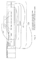
- Fig. 2 shows a full MBUS application layer string (EN 13757-3) with data record headers DRH1, DRH2, DRH3 as well as the associated data Data1, Data2, Data3.
- the signature PS in the C-mode header is a Cyclic Redundancy Check (CRC) checksum calculated on the control information CI, the Header, and data record headers DRH1, DRH2, DRH3.
- CRC Cyclic Redundancy Check
- the data record headers DRH1, DRH2, DRH3 occupy a significant part of the total MBUS string, and in case a limited amount of different types of data formats are used, the signature PS, e.g.
- a first checksum CRC1 is included calculated on the whole MBUS string.
- a second CRC2 is included, which is calculated over the whole frame, so as to allow verification of the data transport.
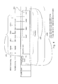
- Fig. 3 shows a data format MBUS string where only the data record headers DRH1, DRH2, DRH3 are included, i.e. no data values are included.
- the signature PS is selected to be a CRC checksum of the control information CI, the Header, and the data record headers DRH1, DRH2, DRH3.
- a first checksum CRC1 is included which is identical with the signature PS.
- a second checksum CRC2 is included, which is calculated over the whole frame, so as to allow verification of the data transport.
- Fig. 4 shows a data MBUS string corresponding to the data format MBUS string in Fig. 3 .
- the data record headers are omitted, and only data values Data1, Data2, Data 3 are included.
- the signature PS is calculated as a CRC checksum over the control information CI, the Header, and the data record headers DRH1, DRH2, DRH3 of the corresponding MBUS format string or the full MBUS string, as illustrated. This allows a receiver of the data Data1, Data2, Data 3 to verify the data format interpreted using the signature PS.
- a first CRC1 checksum is included which is calculated on the whole MBUS string.
- a second checksum CRC2 is included, which is calculated over the whole frame, so as to allow verification of the data transport..
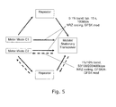
- Transmit only sub-mode C1 The meter will transmit meter ID, meter time and readout values. Values can be transmitted without formatting.
- the bidirectional sub-modes C2a - C2h The meter frequently transmits a frame containing at least the meter ID and opens a listen window after each transmission for the reception of incoming data or commands.
- Fig. 5 illustrates the operation between the different modes and components
- Transmitter performance classes in meter end as 3.3 mode T.
- Transmitter class H T Other to meter, minimum ERP P 15dBm. Protection of meter receivers shall be implemented by limiting other output power to : P o ⁇ -RSSI other - 20dBm
- the radio part of a meter shall, for all parameters, as a minimum conform to the requirements of ETSI EN300 220, Part 1 and Part 2, even if some applications require extended temperature or voltage range.
- Table IX. Mode C General Characteristic Mode Min Typ Max Unit Frequency band: meter to other C1, C2 868.7 868.95 869.2 Mhz Frequency band: other to meter C2abc 869.4 869.525 869.65 Mhz C2d 868.0 868.175 868.3 C2e 868.3 868.425 868.6 C2fgh 868.0 868.300 868.600
- Transmitter duty cycle meter to other C1, C2 0.1 % Transmitter duty cycle: other to meter C2 10 % Notes as in table 8
- VI.2 mode C Physical link parameters for the physical link shall be as listed in Table X.
- Table XI - Mode C Reciever Characteristic Class Sym Min Typ Max Unit Note Sensitivity (BER ⁇ 10-2) or (PER ⁇ 0.2) Other H R P O -100 -105 dBm Sensitivity (BER ⁇ 10-2) or (PER ⁇ 0.2) Meter Hr -100 dBm Mode C2abdef Sensitivity (BER ⁇ 10-2) or (PER ⁇ 0.2) Meter Hr -93 dBm Mode C2cg Sensitivity (BER ⁇ 10-2) or (PER ⁇ 0.2) Meter Hr -86 dBm Mode C2h Blocking Performance 2 Class Notes as table 10
- VI.4 mode C Data encoding
- All communication from meter to other and communication in the C2a, C2b, C2d, C2e and C2f modes other to meter is transmitted as GFSK modulated data, encoded as NRZ, with the low frequency corresponding to a binary '0'
- C2g and C2h modes other to meter communication is sent as 4-GFSK modulated data, encoded as NRZ, with the lowest frequency corresponding to binary '00', next frequency is corresponding to binary '01', third frequency is corresponding to binary '11' and the highest frequency is corresponding to binary '10'.
- the total preamble (header + synchronisation) sequence for this mode depends on the direction and sub mode:
- the beginning of the preamble + synchronisation sequence from meter to other is equal to the beginning of the same sequence in the T mode, thus a receiver capable of receiving a mix of both types of packets can be designed.
- Nested CRC is used for enhanced data security.
- the first 8 bits of the frame is the length field.
- the field specifies the number of subsequent user data bytes, including control, address, and packet information and the data, and excluding the CRC bytes. A maximum of 254 bytes can be specified.
- the 9th to 48th bit of the frame shall contain the address of the meter. Each manufacturer shall guarantee that the address is unique
- the 49th to 63rd bit of the frame shall contain a unique User/Manufacturer ID of the meter formed from a three letter ISO 646 code (A..Z) as specified in EN 13757-3:2004, 5.5. See Annex B for administration of these three letter codes.
- the 69 th to the 72 nd bit in the frame is the Control field. It specifies the frame type.
- the XXX b code indicates the sub mode.
- a meter in C2 mode shall only listen for other-to-meter communication in the sub mode indicated.
- Sub mode C2a or C2b are default sub modes, and the meter shall always automatically return to one of these sub modes after a Sub mode Timeout Period unless requested otherwise.
- the meter After a C2 mode transmission, the meter shall open a listen window and receive and process a frame if it starts within the listen window (ie. synchronisation word is received), and the address matches the meter address.
- the meter shall reply if a request from other end has been received and processed successfully. The reply shall start after a period defined by Reply Frame Start. The reply is optionally in C1 or C2 mode.
- the coding of the submodes XXX b shall be as specified in table XII.
- CTR Counter mode
- the initialisation vector for the encryption shall consist of a nonce and a block counter.
- the nonce used for each encrypted block shall be equal to the combination of the P-I-C-PR-PS fields and the first 28 bits of the PN field for the first 53 bits.
- the 75 bit wide block counter shall be equal to 0 for the first frame in a session.
- the block counter shall continue counting up in the next frame, if the extension bit is equal to 1.
- the second and the third bit in the Presentation field shall identify the contents of the data-field: Meter to other: YY Data field contains 00 Full MBUS string Full application layer data string containing CI field, header, data record headers and data. The last 2 bytes shall contain a CRC checksum of the complete string. 01 MBUS format string Control information and formatting string ie. CI field, header, and data record headers The last 2 bytes shall contain a CRC checksum of the formatting string. This CRC is identical to the PS field. 10 MBUS data string MBUS data string, i.e. no control, header or data record headers. All data matching a control and formatting need not be transmitted, i.e. the data string can be stopped at any point. The last two bytes shall contain a CRC checksum of the full MBUS string including CI field, formatting and data. 11 Modem communication string The data field shall contain commands and data used for configuration, firmware update, communication intervals etc.
- YY Data field contains 00 Full MBUS string Full application layer string containing CI field, header, data record headers and data. The last 2 bytes shall contain a CRC checksum of the complete string.
- the data field shall contain commands and data used for configuration, firmware update, communication intervals etc
- the 76 th to the 104 th bit of the frame shall contain the Packet Number.
- the 2 nd to the 20 th bit in this field shall be an hour counter, the next 6 bits shall be a minute counter and the last 3 bits shall number packets within each minute.
- the most significant bit shall be 0 if the Packet Number is an absolute value, counted from January first 2000 00:00:00.
- the most significant bit shall be 1 if the Packet number is a relative value.
- the last bit is NOT used in the encryption scheme, and only identical encrypted frames shall be transmitted if Packet numbers only differ by the LSB. This enables repetition of packets without recalculation of the encryption.
- the PN value shall reflect the clock in the meter.
- the PN value shall meet 3 requirements:
- the PN value shall be equal to or higher than the PN value received from the meter
- the PN value shall be lower than the PN value received from the meter plus the PN Value Time Out.
- the PN value shall be higher than the PN value from the last other-to-meter communication.
- JF being the Jitter factor
- PN x being the x th bit of the PN field
- a x being the x th bit of the A field.
- the unit of t D shall be milliseconds.
- Packets within a session shall not be jittered relative to each other.
- the 105 th to the 120 th bit of the frame shall contain the packet signature.
- the PS field shall contain a signature of all control and formatting bytes belonging to the data field.
- the signature shall identify the sequence and the value of the control and formatting bytes.
- Short and long data strings can share the same signature, as long as the data are truncated from the end, and the sequence is preserved.
- a preferred signature is the CRC checksum of the CI field, header and data record headers.
- the data shall contain formatting and/or data according to the PR field.
- the last two bytes shall be a CRC checksum of the application data.
- this CRC checksum shall be calculated on the full MBUS packet including CI field, header, data record headers and data.
- the CRC shall be generated according to FT3 of EN 60870-5-1.
- the CRC polynomial is: x 16 +x 13 +x 12 +x 11 +x 10 +x 8 +x 6 +x 5 +x 2 +1
- the initial value is: 0
- the CRC shall be computed over the information of the entire frame (including the Length field), and shall be generated according to FT3 of EN 60870-5-1.
- the CRC polynomial is: x 16 +x 13 +x 12 +x 11 +x 10 +x 8 +x 6 +x 5 +x 2 +1
- the initial value is: 0
- Fig. 6 finally illustrates preferred methods for counter mode encryption and counter mode decryption.
- the invention provides a data format for communicating data, e.g. for automatic reading of consumption meters, the data format comprising a data packet comprising 1) a header for an identification of a device transmitting the data packet, 2) a data field for data, 3) a signature representing a coded information regarding a format of the data field, and 4) a check sum, such as a Cyclic Redundancy Check sum, allowing a receiver to verify interpretation of the data in the data field.
- a preferred consumption meter for measuring a consumed quantity value transmits this quantity value according to the data format.
- the consumption meter may repeatedly transmit in RF format such data packet in which the data field comprises a time of measuring and the quantity value.
- Such consumption meter is suited for automatic drive-by reading and it is suited for battery operation, since the data format helps to save power as data format information can be omitted.
- a reading system is informed about the data format by means of the signature and an identification of the consumption meter, and based on pre-stored information linked to the signature, the system can interpret the read quantity data.
Landscapes
- Engineering & Computer Science (AREA)
- Computer Networks & Wireless Communication (AREA)
- Signal Processing (AREA)
- Quality & Reliability (AREA)
- Physics & Mathematics (AREA)
- General Physics & Mathematics (AREA)
- Mobile Radio Communication Systems (AREA)
- Arrangements For Transmission Of Measured Signals (AREA)
Priority Applications (1)
| Application Number | Priority Date | Filing Date | Title |
|---|---|---|---|
| EP09162282A EP2088706A3 (fr) | 2009-06-09 | 2009-06-09 | Format de données pour économiser de l'énergie dans un module de communication |
Applications Claiming Priority (1)
| Application Number | Priority Date | Filing Date | Title |
|---|---|---|---|
| EP09162282A EP2088706A3 (fr) | 2009-06-09 | 2009-06-09 | Format de données pour économiser de l'énergie dans un module de communication |
Publications (2)
| Publication Number | Publication Date |
|---|---|
| EP2088706A2 true EP2088706A2 (fr) | 2009-08-12 |
| EP2088706A3 EP2088706A3 (fr) | 2010-03-17 |
Family
ID=40791332
Family Applications (1)
| Application Number | Title | Priority Date | Filing Date |
|---|---|---|---|
| EP09162282A Withdrawn EP2088706A3 (fr) | 2009-06-09 | 2009-06-09 | Format de données pour économiser de l'énergie dans un module de communication |
Country Status (1)
| Country | Link |
|---|---|
| EP (1) | EP2088706A3 (fr) |
Cited By (10)
| Publication number | Priority date | Publication date | Assignee | Title |
|---|---|---|---|---|
| WO2013050037A1 (fr) | 2011-10-03 | 2013-04-11 | Miitors Aps | Protocole radio pour communication avec des compteurs |
| WO2014081477A1 (fr) * | 2012-11-26 | 2014-05-30 | Intel Corporation | Procédés et agencements pour décoder des communications |
| WO2015138540A1 (fr) * | 2014-03-12 | 2015-09-17 | Cameron International Corporation | Synchronisation de réseau pour dispositifs maîtres et asservis |
| US9335192B2 (en) | 2009-04-02 | 2016-05-10 | Kamstrup A/S | Ultrasonic flow meter unit having a membrane and a top part forming a water-tight casing for the transducers and the circuit board |
| EP2908096B1 (fr) * | 2014-02-12 | 2017-07-26 | Schneider Electric Industries SAS | Dispositif électronique de mesure apte à afficher des données sous forme d'un code matriciel à deux dimensions, lecteur électronique, installation électronique et procédé de transmission associés |
| EP2360484B1 (fr) | 2010-01-22 | 2018-10-17 | Diehl Metering Systems GmbH | Procédé de transmission de données radio bidirectionnel |
| DE102017127242A1 (de) * | 2017-11-20 | 2019-05-23 | Qundis Gmbh | Verbrauchswertsendeeinheit und Verfahren zu deren Betrieb, Verbrauchswertempfangseinheit und Verfahren zu deren Betrieb sowie Sender-Empfänger-Anordnung und Verfahren zu deren Betrieb |
| EP3537109A1 (fr) * | 2018-03-07 | 2019-09-11 | H. Stoll AG & Co. KG | Procédé de saisie de valeurs mesurées |
| EP3580948B1 (fr) | 2017-02-10 | 2020-11-18 | Kamstrup A/S | Système et procédé de communication par radiofréquence |
| CN114765527A (zh) * | 2021-01-14 | 2022-07-19 | 华东师范大学 | 一种gfsk信号维特比解调的联合同步方法 |
Family Cites Families (3)
| Publication number | Priority date | Publication date | Assignee | Title |
|---|---|---|---|---|
| US4739486A (en) * | 1982-12-08 | 1988-04-19 | Pitney Bowes Inc. | Modifying a firmware variable in an electronic postage meter |
| US5956757A (en) * | 1996-03-22 | 1999-09-21 | Adaptec, Inc. | Method and apparatus for generating addresses |
| AU2003270323A1 (en) * | 2003-09-05 | 2005-04-21 | Itron, Inc. | Field data collection and processing system, such as for electric, gas, and water utility data |
-
2009
- 2009-06-09 EP EP09162282A patent/EP2088706A3/fr not_active Withdrawn
Cited By (19)
| Publication number | Priority date | Publication date | Assignee | Title |
|---|---|---|---|---|
| US9335192B2 (en) | 2009-04-02 | 2016-05-10 | Kamstrup A/S | Ultrasonic flow meter unit having a membrane and a top part forming a water-tight casing for the transducers and the circuit board |
| US9658090B2 (en) | 2009-04-02 | 2017-05-23 | Kamstrup A/S | Ultrasonic flow meter unit having a fixing mechanism to fix the water-tight casing including a membrane to a housing including a measuring tube |
| EP2360484B1 (fr) | 2010-01-22 | 2018-10-17 | Diehl Metering Systems GmbH | Procédé de transmission de données radio bidirectionnel |
| DE102010005587B4 (de) * | 2010-01-22 | 2019-11-14 | Diehl Metering Systems Gmbh | Bidirektionales Funk-Datenübertragungsverfahren |
| US10746566B2 (en) | 2011-10-03 | 2020-08-18 | Apator Militors ApS | Radio protocol for communication with meter devices |
| WO2013050037A1 (fr) | 2011-10-03 | 2013-04-11 | Miitors Aps | Protocole radio pour communication avec des compteurs |
| US9407732B2 (en) | 2012-11-26 | 2016-08-02 | Intel Corporation | Methods and arrangements to decode communications |
| WO2014081477A1 (fr) * | 2012-11-26 | 2014-05-30 | Intel Corporation | Procédés et agencements pour décoder des communications |
| EP2908096B1 (fr) * | 2014-02-12 | 2017-07-26 | Schneider Electric Industries SAS | Dispositif électronique de mesure apte à afficher des données sous forme d'un code matriciel à deux dimensions, lecteur électronique, installation électronique et procédé de transmission associés |
| US10502596B2 (en) | 2014-02-12 | 2019-12-10 | Schneider Electric Industries Sas | Electronic measurement device capable of displaying data in the form of two dimensional matrix code, electronic reader, electronic installation and transmission method associated therewith |
| WO2015138540A1 (fr) * | 2014-03-12 | 2015-09-17 | Cameron International Corporation | Synchronisation de réseau pour dispositifs maîtres et asservis |
| US10783030B2 (en) | 2014-03-12 | 2020-09-22 | Sensia Llc | Network synchronization for master and slave devices |
| EP3580948B1 (fr) | 2017-02-10 | 2020-11-18 | Kamstrup A/S | Système et procédé de communication par radiofréquence |
| US11448522B2 (en) | 2017-02-10 | 2022-09-20 | Kamstrup A/S | Radio frequency communication system and method |
| DE102017127242A1 (de) * | 2017-11-20 | 2019-05-23 | Qundis Gmbh | Verbrauchswertsendeeinheit und Verfahren zu deren Betrieb, Verbrauchswertempfangseinheit und Verfahren zu deren Betrieb sowie Sender-Empfänger-Anordnung und Verfahren zu deren Betrieb |
| DE102017127242B4 (de) | 2017-11-20 | 2021-11-04 | Qundis Gmbh | Verbrauchswertsendeeinheit und Verfahren zu deren Betrieb, Verbrauchswertempfangseinheit und Verfahren zu deren Betrieb sowie Sender-Empfänger-Anordnung und Verfahren zu deren Betrieb |
| EP3537109A1 (fr) * | 2018-03-07 | 2019-09-11 | H. Stoll AG & Co. KG | Procédé de saisie de valeurs mesurées |
| CN114765527A (zh) * | 2021-01-14 | 2022-07-19 | 华东师范大学 | 一种gfsk信号维特比解调的联合同步方法 |
| CN114765527B (zh) * | 2021-01-14 | 2023-09-19 | 华东师范大学 | 一种gfsk信号维特比解调的联合同步方法 |
Also Published As
| Publication number | Publication date |
|---|---|
| EP2088706A3 (fr) | 2010-03-17 |
Similar Documents
| Publication | Publication Date | Title |
|---|---|---|
| EP2088706A2 (fr) | Format de données pour économiser de l'énergie dans un module de communication | |
| EP1779610B1 (fr) | Systeme et procede pour ameliorer l'efficacite en termes de puissance dans un reseau a ressources partagees | |
| AU2004205348B2 (en) | Data communication protocol in an automatic meter reading system | |
| ES2710320T3 (es) | Aparatos y procedimientos para la compresión de cabeceras de control de acceso a medios | |
| US9680970B2 (en) | System and methods for communicating between an implantable medical device and an external device | |
| CA2234721A1 (fr) | Simplification du decodage des mots de code dans un systeme de radiocommunication | |
| US20050265333A1 (en) | Method for enabling efficient multicast transmission in a packet-based network | |
| WO2007033313A2 (fr) | Mecanisme de transmission rapide de messages de commande pour les communications dans un reseau sans fil | |
| EP3074912B1 (fr) | Protection d'en-tête de paquet pour réseaux utilitaires | |
| EP2160876B1 (fr) | Procédé, signal et appareil de gestion de la transmission et de la réception d'informations d'un canal de radiodiffusion | |
| US20080137594A1 (en) | Apparatus and method for increasing a service coverage area of a broadcast channel in wireless communication system by using an harq scheme | |
| US7778281B2 (en) | Wireless communication apparatus | |
| CN113098809B (zh) | 一种软件自适应解码方法、装置及无线充电系统 | |
| US7525966B2 (en) | Wireless communication system for multicast communications | |
| US10257328B2 (en) | Method and apparatus for control frame extension | |
| GB2514623A (en) | Radio data packets | |
| CN117596311A (zh) | Rfid芯片的多协议解码电路 | |
| WO2006083996A2 (fr) | Protocole de communication de donnees d'un systeme automatique de releve de compteurs | |
| KR20120062125A (ko) | 비디오 및 오디오 통신 시스템에서 패킷 오류 표시 장치 및 방법 | |
| US20080279173A1 (en) | Method to Synchronize Receiver's Clock to Transmitter's Clock at Sub-100Nsec | |
| US20180351860A1 (en) | Network communication system with node energy reduction packet protocol | |
| US20150349919A1 (en) | Radio data packets | |
| US20200076929A1 (en) | Method for transmitting information | |
| CN114337905A (zh) | 利用FCS特性进行Wi-Fi反向散射隐蔽通信方法及系统 | |
| US20050086182A1 (en) | Optimized bubble up receiver AMR system |
Legal Events
| Date | Code | Title | Description |
|---|---|---|---|
| PUAI | Public reference made under article 153(3) epc to a published international application that has entered the european phase |
Free format text: ORIGINAL CODE: 0009012 |
|
| AK | Designated contracting states |
Kind code of ref document: A2 Designated state(s): AT BE BG CH CY CZ DE DK EE ES FI FR GB GR HR HU IE IS IT LI LT LU LV MC MK MT NL NO PL PT RO SE SI SK TR |
|
| PUAL | Search report despatched |
Free format text: ORIGINAL CODE: 0009013 |
|
| AK | Designated contracting states |
Kind code of ref document: A3 Designated state(s): AT BE BG CH CY CZ DE DK EE ES FI FR GB GR HR HU IE IS IT LI LT LU LV MC MK MT NL NO PL PT RO SE SI SK TR |
|
| AX | Request for extension of the european patent |
Extension state: AL BA RS |
|
| RIC1 | Information provided on ipc code assigned before grant |
Ipc: G01D 4/00 20060101ALI20100210BHEP Ipc: H04L 1/00 20060101AFI20090630BHEP |
|
| STAA | Information on the status of an ep patent application or granted ep patent |
Free format text: STATUS: THE APPLICATION IS DEEMED TO BE WITHDRAWN |
|
| 18D | Application deemed to be withdrawn |
Effective date: 20100918 |