EP2088933B1 - Vorrichtung zur abgabe eines verschlusspfropfes - Google Patents
Vorrichtung zur abgabe eines verschlusspfropfes Download PDFInfo
- Publication number
- EP2088933B1 EP2088933B1 EP07822325A EP07822325A EP2088933B1 EP 2088933 B1 EP2088933 B1 EP 2088933B1 EP 07822325 A EP07822325 A EP 07822325A EP 07822325 A EP07822325 A EP 07822325A EP 2088933 B1 EP2088933 B1 EP 2088933B1
- Authority
- EP
- European Patent Office
- Prior art keywords
- plug
- channel
- pushing
- distal end
- inserter
- Prior art date
- Legal status (The legal status is an assumption and is not a legal conclusion. Google has not performed a legal analysis and makes no representation as to the accuracy of the status listed.)
- Not-in-force
Links
Images


Classifications
-
- A—HUMAN NECESSITIES
- A61—MEDICAL OR VETERINARY SCIENCE; HYGIENE
- A61B—DIAGNOSIS; SURGERY; IDENTIFICATION
- A61B17/00—Surgical instruments, devices or methods
- A61B17/0057—Implements for plugging an opening in the wall of a hollow or tubular organ, e.g. for sealing a vessel puncture or closing a cardiac septal defect
-
- A—HUMAN NECESSITIES
- A61—MEDICAL OR VETERINARY SCIENCE; HYGIENE
- A61B—DIAGNOSIS; SURGERY; IDENTIFICATION
- A61B17/00—Surgical instruments, devices or methods
- A61B2017/00004—(bio)absorbable, (bio)resorbable or resorptive
-
- A—HUMAN NECESSITIES
- A61—MEDICAL OR VETERINARY SCIENCE; HYGIENE
- A61B—DIAGNOSIS; SURGERY; IDENTIFICATION
- A61B17/00—Surgical instruments, devices or methods
- A61B17/0057—Implements for plugging an opening in the wall of a hollow or tubular organ, e.g. for sealing a vessel puncture or closing a cardiac septal defect
- A61B2017/00646—Type of implements
- A61B2017/00654—Type of implements entirely comprised between the two sides of the opening
Definitions
- the present invention relates to a device for delivering a plug in a conduit of the human or animal body.
- reconstructive surgery of the aorta especially after an abdominal aortic aneurysm is a common operation and particularly prevalent in people over 65 years that represents 150,000 to 200,000 operations per year in the world.
- the technique involves clasping the aneurysm sac, opening it and evacuating the clot, and finally replacing the aneurysm with a vascular prosthesis.
- the lumbar arteries are five in number. They originate in the posterior aspect of the abdominal aorta. Lumbar arteries walk along the lumbar vertebrae, dividing into two branches: a dorso-spinal (posterior) branch and an abdominal or intercostal lumbar (anterior) branch.
- the lumbar arteries are at this time updated. They are then a source of blood reflux: the presence of an opening in the open air promotes the reflux since it constitutes an opening on a low pressure environment, unlike the arterial network which is a high pressure environment (relative pressure of the order of 100 mmhg).
- the blood flows back and forth from a peripheral arterial network of the aorta, which is clamped.
- the conventional technique is to ligate the lumbar arteries with a suture.
- the leaking arteries can be blocked by the surgeons 'assistants' fingers or compresses.
- the arteries remain ligated after the operation because there is a peripheral network that replaces the circulation of these arteries. This loss of blood is one of the most important in this surgery.
- the time during which the aorta is clamped is critical for the patient. Any means of limiting this time as well as blood loss can improve the postoperative course for the patient and thus operate patients more crazy.
- an occlusion plug is put in place.
- the cap is in the compressed state before being introduced into the vessel and then resumes its original expanded form once set up.
- the lumbar arteries have a small diameter of between 1 and 2.5 mm and have thin and fragile walls. Expansion of the artery beyond its normal diameter to insert a plug could rupture the artery and cause hemorrhage. In addition, these arteries may have calcifications that make them extremely rigid. It is difficult to dilate them.
- the various known devices have a single constrictor tube receiving the already compressed plug.
- the disadvantage of these devices is the risk that the cap does not expand properly once set up because of a shape remanence.
- the invention proposes a device for delivering a plug in a conduit of the human or animal body comprising an introducer provided with a guide channel and means for pushing the plug in the channel characterized by the fact that said channel is configured to radially compress the plug during its movement towards the distal end of the channel and that the means for pushing the plug comprise at least two nested rods slidable into one another.
- the compression is thus performed only a few seconds before its implementation respecting its integrity. This allows the cap to retain all its elasticity characteristics.
- the cap is composed of a succession of compartments of decreasing section or according to another embodiment the channel has a trunk-shaped profile of cone.
- the channel is located at the distal end of said introducer in a removable tip. This embodiment allows the device to be sterilizable or to be disposable.
- the invention also relates to a method for compressing a stopper characterized in that a delivery device as described above is used and that the stopper is introduced at the proximal end of a removable tip into a channel.
- the removable tip is connected to an apparatus comprising compression means, a longitudinal pressure is exerted on the removable tip so as to introduce the compression means into the channel and to push the plug towards the distal end of the channel where it undergoes a first phase of radial compression, the removable tip is disconnected from the device, the removable tip is connected to an introducer comprising terminal thrust means comprising at least two rods nested one inside the other, the terminal thrust means are actuated to move the plug towards the distal end of the channel where it undergoes a second phase of radial compression.
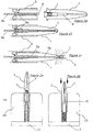
- the present invention relates to a device for delivering a plug 1 in a conduit 2 of the human or animal body comprising an introducer 3 provided with a guide channel 4 and means for pushing the plug 1 into the channel 4 characterized by the fact said channel 4 is configured to radially compress the plug 1 during its movement towards the distal end of the channel 4.
- the channel 4 is composed of a succession of compartments 6.17.18 of decreasing section.
- the last compartment is of section slightly smaller than the diameter of the duct 2 to occlude.
- the plug 1 is put in place in the conduit 2 without damaging the walls.
- the volume of each compartment is constant, that is to say that the sections of the compartments are decreasing, the length of each compartment is increasing.
- the reduction of section may be continuous and in particular carried out by a profile in the form of a truncated cone.
- the channel 4 is located at the distal end of said introducer 3 at least partially in a removable tip 7.
- the delivery device can be resterilizable or disposable or a composition of both possibilities.
- the channel 4 is composed of three parts: a receiving compartment 17 of the cap 1, an ejection compartment 18 of the cap 1, and, between these two compartments, a radial compression zone 6. This is the passage of a compartment to the other through the zone 6 which radially compresses the plug 1.
- the plug 1 is placed at the proximal end of the removable tip 7 in the receiving compartment 17, in substantially uncompressed or uncompressed form. Its insertion is therefore very practical.
- the compression zone 6 of the channel 4 is composed of a succession of compartments of decreasing section.
- the last compartment, the ejection chamber 18, has the thinnest section.
- the compression zone 6 of the channel 4 is composed of a frustoconical portion.
- the means for pushing the stopper 1 act by direct mechanical pressure on the stopper 1, to change it from the receiving compartment 17 to the ejection chamber 18, through the compression zone 6.
- mechanical pressure Direct means that the means for pushing come into contact with the rear surface of the plug 1.
- the means for pushing have a bearing section which decreases as the thrust increases.
- it is one or more solid rods 9 of decreasing section.
- rods 9 are interleaved to reproduce a flat face to push the plug 1 with the widest possible support surface.
- a rod 9 makes a longitudinal displacement in the channel 4 and pushes the plug 1 in the next compartment or in the frustoconical section.
- the plug 1 is at this stage compressed radially in the last ejection compartment 18.
- one of the rods 9 has a section reduction at its distal end.
- the means for pushing have a bearing surface on the plug 1 proportional to the section of the plug.
- the means for pushing do not deteriorate the plug 1.
- the device may be provided with intermediate means acting by indirect mechanical pressure.
- indirect mechanical pressure is meant, for example, that the means for pushing are partially malleable, as shown in FIG. figure 3 .
- the means for pushing in part malleable may be based on silicone or any other deformable material.
- the means for pushing comprise a malleable material which transmits the thrust force generated by a fluid such as a gas or a liquid or by a solid such as a rod or nested rods 9.
- the means for pushing comprise an intermediate fluid intended to transmit the force of the nested rods 9 on said plug 1.
- the fluid used may be a liquid or a gas. It can be compressible or not.
- the means for pushing must be sealed to avoid any risk of leakage of fluid and allow the thrust of the plug 1.
- a rod may be provided at its distal end with sealing means.
- the plug 1 used must be compatible with the fluid. That is, the plug must not be degraded by the fluid and must be fluid tight.
- said introducer 3 is provided at its distal end with discharge means 10 intended to avoid overpressure.
- This discharge means 10 is advantageously constituted by a valve calibrated at a predetermined pressure placed in a pipe communicating at one end with the channel 4 and at the other end with the outside of the device.
- this evacuation means 10 comprises an orifice which opens during the movement of the piston during the compression of the plug 1.
- the plug 1 has radial and / or longitudinal expansion characteristics so that it is brought to the site to be occluded in a compressed position and when it is released, it resumes an expanded shape.
- the plug 1 is made of a biocompatible material of the polymer type such as silicone, silicone foam, polyurethane, a hydrophilic material, a shape memory polymer, hydrogel or biological such as collagen or metal such as than stainless steel or alloy in shape memory.
- a biocompatible material of the polymer type such as silicone, silicone foam, polyurethane, a hydrophilic material, a shape memory polymer, hydrogel or biological such as collagen or metal such as than stainless steel or alloy in shape memory.
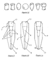
- the plug 1 can have different geometries of types represented in the figure 12 such as a cylinder, a shell, an ovoid, a sphere, a champagne cork, T, truncated cone, diabolo, umbrella.
- Said cap 1 may have means for promoting its anchoring in the conduit 2 where it will be implanted (pins, pins, scales, streaks ).
- the plug 1 has a reinforced end stronger during the pushing by the means for pushing 5.
- the reinforced end may be made by heat treatment or by a second material of greater hardness characteristic.
- the reinforced layer of the cap 1 must be sufficient to withstand the forces of the means for pushing.
- the layer may represent 1/10 of the total thickness of the plug 1.
- the reinforced layer made of a material that is stronger than the material of the stopper 1 can be attached by gluing or by molding onto the stopper 1.
- connection between the introducer 3 and its removable tip 7 is formed by a bayonet.
- the bayonet is formed of a slot at the distal end of said introducer 3 adapted to receive connection lugs 11 located on the proximal portion of the removable tip 7 or vice versa.
- connection between the introducer 3 and said removable tip 7 is made by screwing.
- connection means may be used for the connection between the introducer 3 and the removable tip 7 such as clipping or any other quick connection means.
- Said delivery device aims to introduce the plug 1 into a conduit 2 of the human or animal body.
- the plug 1 is made of relatively hard material to withstand the compressive force of the plug 1.
- the material of the introducer 3 may be metal or a polymer, it may be transparent or not or have a viewing window to allow see and check the ejection of the plug 1.
- the introducer 3 is provided with a lug intended to facilitate the positioning of said device opposite the duct 2 to occlude.
- said introducer 3 is provided at its distal end with a bearing surface 8 intended to allow better support of the device on the periphery of the conduit 2 to occlude.
- this bearing surface 8 is an enlarged bearing surface 13 constituted by a larger diameter than the diameter of the end of the removable tip 7 thus forming a support ring.
- the compression phase and the final thrust phase for the delivery of the plug 1 are successively within the introducer 3 by a prolonged thrust of the plug 1 in the channel 4.
- this generally involves the use of the interlocking of several thrust rods. Indeed, it is necessary to have rods of decreasing diameter to cooperate with the largest possible area of the rear of the plug 1 while passing successively through the compartments of decreasing section or frustoconical portion. A rod then performs the compression placement of the plug and another rod, capable of longitudinal translation in the first, serves for the delivery of the plug 1.
- the compression phase and the final thrust phase do not operate both within the introducer but in two separate elements.
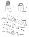
- the means for pushing the stopper 1 comprise compression means located in an apparatus 15 separate from the introducer 3 and terminal pushing means 5 located in the introducer 3.
- the apparatus 15 and the compression means are capable of to cooperate with the removable tip 7 and are intended to compress the plug 1 in the distal portion of said removable tip 7.
- said apparatus 15 is a support 12 provided with at least one rod 16 and advantageously two nested rods 9 one inside the other, able to cooperate with said removable endpiece 7 before it is connected to said introducer 3.
- the nested rods 9 are situated at the level of the apparatus 15.
- the plug 1 is compressed in the channel 4 by the action of the nested rods 9 in the apparatus 15 and then the removable endpiece 7 is attached to the introducer 3 which comprises at least one rod 9 for ejecting the stopper 1 outside the channel 4.
- the removable tip 7 is placed upside down around the compression means. It is supported on a return spring which pushes the removable end piece 7 in the direction opposite to the support 12.
- the device 15 is adapted to cooperate with the connection lugs 11 of the removable tip 7.
- the lugs then also have a role of maintenance in the apparatus 15.
- the removable tip 7 When the removable tip 7 is placed on the device 15, it is locked in rotation and can not come out. The only way to extract it and press on it and turn it a quarter of a turn to bring the lugs of the removable tip 7 free of their stop. During this movement, the plug 1 is transferred from the receiving compartment 17 to the compression zone or to the ejection compartment 18 by the action of the compression means.
- the advantage of the device 15 is that the compression of the plug 1 is made only a few seconds before the introduction respecting the integrity of said plug 1. This keeps the plug all its characteristics of elasticity.
- the compression of the stopper 1 is carried out by the apparatus 15 provided with the compression means before the connection of the removable endpiece 7 to the introducer 3.
- the plug 1 is first inserted into the receiving compartment 17, at the proximal end of said removable tip 7, it is then placed on the apparatus 15 provided with at least one rod 16. A longitudinal pressure on said removable tip 7 causes the rod 16 of the compression means to be introduced into the channel 4 of the removable tip 7. The plug 1 is then pushed into the channel 4 where it undergoes radial compression.
- the removable tip 7, whose plug 1 is at this stage compressed at the distal end in the ejection compartment 18, is connected to the introducer 3 by various connection means described above.
- the compression of the plug 1 is performed during the connection of the removable tip 7 on the introducer 3.
- a movable rod 9b of the introducer 3, nested in the rod 9a, is actuated and pushed by pushing the plug 1 compressed out of the device.
- the compression of the plug 1 is performed after the connection of the removable tip 7 on the introducer 3.
- the removable tip 7 is connected to the introducer 3 by various connection means described above.
- the compression of the plug 1 is done by the actuation of the means for pushing.
- the means for pushing allow a compression of the plug 1 and its ejection.
- the two compression and ejection phases can be achieved by a single actuation means for pushing or by successive actuations means for pushing.
- the delivery device is an ancillary having the conventional form of laparoscopic instrument.
- a trigger provides translational movement to a tie rod included in a tube. Upon actuation of the trigger the tie rod is moved (translational movement of the proximal portion of the tube to the distal portion).
- the system can be lubricated by a viscous product or a liquid to limit the forces during compression and ejection.
- a storage housing 14 may exist in the body of the introducer 3.
- the storage housing 14 allows for storing more than one plug 1 in the device in little or no compressed form.
- the storage housing 14 may be in the form of a barrel.
- the rotation of the barrel causes the alignment of the plug 1 relative to the means for pushing.
- the barrel can be rotated manually by the practitioner or automatically as soon as the means for pushing are no longer facing a stopper 1.
- the storage housing 14 may also be of longitudinal shape for storing the plugs 1 behind each other.
- Means for advancing the plugs may be used to advance the plugs 1 and to successively align one with the means for pushing.
Landscapes
- Health & Medical Sciences (AREA)
- Surgery (AREA)
- Life Sciences & Earth Sciences (AREA)
- Animal Behavior & Ethology (AREA)
- Public Health (AREA)
- Engineering & Computer Science (AREA)
- Biomedical Technology (AREA)
- Heart & Thoracic Surgery (AREA)
- Medical Informatics (AREA)
- Molecular Biology (AREA)
- Cardiology (AREA)
- General Health & Medical Sciences (AREA)
- Nuclear Medicine, Radiotherapy & Molecular Imaging (AREA)
- Veterinary Medicine (AREA)
- Surgical Instruments (AREA)
- Infusion, Injection, And Reservoir Apparatuses (AREA)
- Taps Or Cocks (AREA)
- Preventing Unauthorised Actuation Of Valves (AREA)
- Electrical Discharge Machining, Electrochemical Machining, And Combined Machining (AREA)
- Auxiliary Devices For Machine Tools (AREA)
- Threshing Machine Elements (AREA)
Claims (15)
- Ausgabevorrichtung für einen Stopfen (1) in einen Kanal (2) des menschlichen oder tierischen Körpers, bestehend aus einem Einführteil (3) mit einem Führungskanal (4), das derart gestaltet ist, dass der Stopfen (1) bei seiner Bewegung in Richtung distales Ende des Führungskanals (4) radial zusammengepresst wird, gekennzeichnet dadurch, dass die Mittel zur Vorwärtsdrücken des Stopfens (1) mindestens zwei sich überlappende Stäbe (9) besitzen, die ineinander gleiten können.
- Vorrichtung gemäß Patentanspruch 1, gekennzeichnet dadurch, dass der Führungskanal (4) aus einer Folge von Abteilen mit abnehmendem Querschnitt besteht.
- Vorrichtung gemäß Patentanspruch 1, gekennzeichnet dadurch, dass der Führungskanal (4) ein kegelstumpfförmiges Profil besitzt, das dazu bestimmt ist, den Querschnitt des Führungskanals (4) in Richtung auf sein distales Ende hin zu verringern.
- Vorrichtung gemäß einem der vorstehenden Patentansprüche, gekennzeichnet dadurch, dass der Führungskanal (4) sich am distalen Ende des Einführteils (3) zumindest teilweise in einem abnehmbaren Endstück (7) befindet.
- Vorrichtung gemäß Patentanspruch 4, gekennzeichnet dadurch, dass die Mittel zum Vorwärtsdrücken des Stopfens (1) folgende Elemente besitzen:- Mittel zum Zusammenpressen in einem Gerät (15), an welches das Endstück angeschlossen werden kann, und- Mittel zur abschließenden Druckaufgabe (5), die sich im Einführteil (3) befinden.
- Vorrichtung gemäß Patentanspruch 4 oder 5, gekennzeichnet dadurch, dass die Verbindung zwischen dem Einführteil (3) und seinem abnehmbaren Endstück (7) durch ein Bajonettsystem hergestellt wird.
- Vorrichtung gemäß Patentanspruch 4 oder 5, gekennzeichnet dadurch, dass die Verbindung zwischen dem Einführteil (3) und seinem abnehmbaren Endstück (7) eine Verschraubung ist.
- Vorrichtung gemäß einem der vorstehenden Patentansprüche, gekennzeichnet dadurch, dass ein Stab (9) an seinem distalen Ende eine Querschnittsverringerung aufweist.
- Vorrichtung gemäß einem der vorstehenden Patentansprüche, gekennzeichnet dadurch, dass das Einführteil (3) mit einem Vorsprung versehen ist, um die Positionierung der Vorrichtung vor dem zu verschließenden Kanal zu erleichtern.
- Vorrichtung gemäß einem der vorstehenden Patentansprüche, gekennzeichnet dadurch, dass das Einführteil (3) an seinem distalen Ende mit einer vergrößerten Anlagefläche (13) versehen ist, um das Anlegen der Vorrichtung an dem Umfang des zu verschließenden Kanals zu ermöglichen (2).
- Vorrichtung gemäß einem der vorstehenden Patentansprüche, gekennzeichnet dadurch, dass das Einführteil (3) eine Aufnahmeöffnung (14) besitzt, die zur Lagerung der Stopfen (1) vor ihrer Verwendung bestimmt ist.
- Vorrichtung gemäß Patentanspruch 11, gekennzeichnet dadurch, dass die Aufnahmeöffnung (14) ein Magazin zur Lagerung und Ausgabe der Stopfen (1) besitzt.
- Vorrichtung gemäß einem der vorstehenden Patentansprüche, gekennzeichnet dadurch, dass die Mittel zum Vorwärtsdrücken des Stopfens (1) eine Fluid-Zwischenlage enthalten, um die Kraft der einander überlappenden Stäbe (9) auf den Stopfen (1) zu übertragen.
- Vorrichtung gemäß Patentanspruch 13, gekennzeichnet dadurch, dass das distale Ende des Einführteils (3) mit einer Entleerungseinrichtung (10) versehen ist, die zur Vermeidung von Überdrücken bestimmt ist.
- Verfahren zum Zusammenpressen eines Stopfens (1), gekennzeichnet dadurch, dass eine Ausgabevorrichtung gemäß Patentanspruch 5 verwendet wird und- der Stopfen (1) am proximalen Ende eines abnehmbaren Endstückes (7) in einen Führungskanal (4) eingeführt wird,- das abnehmbare Endstück (7) an ein Gerät (15) angeschlossen wird, das Mittel zum Zusammenpressen besitzt,- auf das abnehmbare Endstück (7) ein Druck in Längsrichtung ausgeübt wird, so dass die Mittel zum Zusammenpressen in den Führungskanal (4) eingeführt werden können und der Stopfen (1) in Richtung distales Ende des Führungskanals (4) vorwärts gedrückt wird,- das abnehmbare Endstück (7) vom Gerät (15) getrennt ist,- das abnehmbare Endstück (7) an ein Einführteil (3) angeschlossen wird, das Mittel zur abschließenden Druckaufgabe (5) besitzt,- die Mittel zur abschließenden Druckaufgabe (5) derart betätigt werden, dass der Stopfen (1) in Richtung distales Ende des Führungskanals (4) bewegt wird.
Applications Claiming Priority (2)
| Application Number | Priority Date | Filing Date | Title |
|---|---|---|---|
| FR0654900A FR2908284B1 (fr) | 2006-11-14 | 2006-11-14 | Dispositif de delivrance de bouchon d'occlusion. |
| PCT/EP2007/062015 WO2008058880A1 (fr) | 2006-11-14 | 2007-11-07 | Dispositif de delivrance de bouchon d'occlusion |
Publications (2)
| Publication Number | Publication Date |
|---|---|
| EP2088933A1 EP2088933A1 (de) | 2009-08-19 |
| EP2088933B1 true EP2088933B1 (de) | 2010-04-21 |
Family
ID=37866293
Family Applications (1)
| Application Number | Title | Priority Date | Filing Date |
|---|---|---|---|
| EP07822325A Not-in-force EP2088933B1 (de) | 2006-11-14 | 2007-11-07 | Vorrichtung zur abgabe eines verschlusspfropfes |
Country Status (7)
| Country | Link |
|---|---|
| US (1) | US8157838B2 (de) |
| EP (1) | EP2088933B1 (de) |
| AT (1) | ATE464843T1 (de) |
| CA (1) | CA2668904A1 (de) |
| DE (1) | DE602007006044D1 (de) |
| FR (1) | FR2908284B1 (de) |
| WO (1) | WO2008058880A1 (de) |
Families Citing this family (1)
| Publication number | Priority date | Publication date | Assignee | Title |
|---|---|---|---|---|
| CN120884323A (zh) * | 2020-04-03 | 2025-11-04 | 江苏风和医疗器材股份有限公司 | 用于外科器械的分离件、组件及外科套件 |
Family Cites Families (12)
| Publication number | Priority date | Publication date | Assignee | Title |
|---|---|---|---|---|
| US4411275A (en) * | 1981-11-02 | 1983-10-25 | Concord Laboratories, Inc. | Syringe |
| US4790819A (en) * | 1987-08-24 | 1988-12-13 | American Cyanamid Company | Fibrin clot delivery device and method |
| JP2986594B2 (ja) * | 1991-09-26 | 1999-12-06 | ユニ・チャーム株式会社 | 生理用タンポンのアプリケーター |
| US5326350A (en) * | 1992-05-11 | 1994-07-05 | Li Shu Tung | Soft tissue closure systems |
| WO1994026175A1 (en) | 1993-05-06 | 1994-11-24 | Vitaphore Corporation | Embolization device |
| JPH10512470A (ja) * | 1995-01-18 | 1998-12-02 | メドケム プロダクツ,インコーポレーテッド | 組織に止血剤を適用する装置および方法 |
| US6071301A (en) * | 1998-05-01 | 2000-06-06 | Sub Q., Inc. | Device and method for facilitating hemostasis of a biopsy tract |
| US20010045575A1 (en) * | 1998-05-01 | 2001-11-29 | Mark Ashby | Device and method for facilitating hemostasis of a biopsy tract |
| AUPP633798A0 (en) | 1998-10-02 | 1998-10-29 | White, Geoffrey H. | Device for the occlusion of a puncture in a bodily duct |
| US6984219B2 (en) * | 1999-09-23 | 2006-01-10 | Mark Ashby | Depth and puncture control for blood vessel hemostasis system |
| CA2487288A1 (en) * | 2002-05-27 | 2003-12-04 | Shlomo Ben-David | Apparatus for sealing a puncture in a blood vessel |
| US20050090860A1 (en) * | 2003-10-23 | 2005-04-28 | Paprocki Loran J. | Segmented plug for tissue tracts |
-
2006
- 2006-11-14 FR FR0654900A patent/FR2908284B1/fr not_active Expired - Fee Related
-
2007
- 2007-11-07 WO PCT/EP2007/062015 patent/WO2008058880A1/fr not_active Ceased
- 2007-11-07 DE DE602007006044T patent/DE602007006044D1/de active Active
- 2007-11-07 US US12/514,359 patent/US8157838B2/en not_active Expired - Fee Related
- 2007-11-07 CA CA002668904A patent/CA2668904A1/fr not_active Abandoned
- 2007-11-07 AT AT07822325T patent/ATE464843T1/de not_active IP Right Cessation
- 2007-11-07 EP EP07822325A patent/EP2088933B1/de not_active Not-in-force
Also Published As
| Publication number | Publication date |
|---|---|
| DE602007006044D1 (de) | 2010-06-02 |
| ATE464843T1 (de) | 2010-05-15 |
| US8157838B2 (en) | 2012-04-17 |
| FR2908284B1 (fr) | 2009-11-27 |
| EP2088933A1 (de) | 2009-08-19 |
| WO2008058880A1 (fr) | 2008-05-22 |
| FR2908284A1 (fr) | 2008-05-16 |
| US20100042145A1 (en) | 2010-02-18 |
| CA2668904A1 (fr) | 2008-05-22 |
Similar Documents
| Publication | Publication Date | Title |
|---|---|---|
| EP1610691B1 (de) | Vorrichtung zum platzieren eines gefässimplantats | |
| CA2424319C (fr) | Dispositif d'occlusion vasculaire, appareil et procede d'utilisation | |
| EP1033946B1 (de) | Vorrichtung zum einführen einer prothese zur behandlung eines leistenbruchs bei einer zölioskopie | |
| EP2053994B1 (de) | Vorrichtung zum anbringen und abziehen einer auskleidung | |
| FR2783702A1 (fr) | Dispositif autobloquant pour protheses | |
| EP2088933B1 (de) | Vorrichtung zur abgabe eines verschlusspfropfes | |
| EP3772346A1 (de) | Schädeldeckenfixierer | |
| FR2872696A1 (fr) | Introducteur pour intervention endoluminale | |
| BE1016692A3 (fr) | Cartouche pour dispositif d'injection de lentille intraoculaire souple et dispositif pourvu d'une telle cartouche. | |
| EP3781089B1 (de) | System zur freisetzung einer bypass-gefässprothese | |
| EP2242435A1 (de) | Entnehmbares intrauterines system | |
| CN115813661B (zh) | 鼓膜支架、输送装置以及鼓膜支架系统 | |
| FR2979229A1 (fr) | Dispositif de fenestration d'endoprothese | |
| FR2979228A1 (fr) | Endoprothese aortique universelle | |
| FR2847799A1 (fr) | Dispositif de chirurgie endovasculaire | |
| EP2088934B1 (de) | Laparoskopisches distanzstück | |
| WO2023046759A1 (fr) | Dispositif ancillaire et kit pour anastomose | |
| EP2638869B1 (de) | Vorrichtung zum Einsetzen einer Prothese in einen Körperkanal | |
| FR2727021A1 (fr) | Seringue a usage unique comportant un systeme de neutralisation de l'aiguille par escamotage automatique en fin d'injection | |
| WO2026069198A1 (fr) | Instruments de chirurgie orthopédique humaine d'installation d'implants osseux expansibles | |
| WO2026069199A1 (fr) | Instruments de chirurgie orthopédique vétérinaire d'installation d'implants osseux expansibles | |
| WO2017191419A1 (fr) | Système d'injection dirigée intra-osseuse de ciment chirugical | |
| FR2860422A1 (fr) | Dispositif d'application de substances adherentes biocompatible a clapet interne | |
| FR2655550A1 (fr) | Dispositif de drainage chirurgical a action differee. | |
| WO2018167140A1 (fr) | Dispositif d'injection de lentille intraoculaire souple |
Legal Events
| Date | Code | Title | Description |
|---|---|---|---|
| PUAI | Public reference made under article 153(3) epc to a published international application that has entered the european phase |
Free format text: ORIGINAL CODE: 0009012 |
|
| 17P | Request for examination filed |
Effective date: 20090520 |
|
| AK | Designated contracting states |
Kind code of ref document: A1 Designated state(s): AT BE BG CH CY CZ DE DK EE ES FI FR GB GR HU IE IS IT LI LT LU LV MC MT NL PL PT RO SE SI SK TR |
|
| RTI1 | Title (correction) |
Free format text: DEVICE FOR DELIVERING AN OCCLUSION PLUG |
|
| GRAP | Despatch of communication of intention to grant a patent |
Free format text: ORIGINAL CODE: EPIDOSNIGR1 |
|
| DAX | Request for extension of the european patent (deleted) | ||
| GRAS | Grant fee paid |
Free format text: ORIGINAL CODE: EPIDOSNIGR3 |
|
| GRAA | (expected) grant |
Free format text: ORIGINAL CODE: 0009210 |
|
| AK | Designated contracting states |
Kind code of ref document: B1 Designated state(s): AT BE BG CH CY CZ DE DK EE ES FI FR GB GR HU IE IS IT LI LT LU LV MC MT NL PL PT RO SE SI SK TR |
|
| REG | Reference to a national code |
Ref country code: GB Ref legal event code: FG4D Free format text: NOT ENGLISH |
|
| REG | Reference to a national code |
Ref country code: CH Ref legal event code: EP |
|
| REG | Reference to a national code |
Ref country code: IE Ref legal event code: FG4D Free format text: LANGUAGE OF EP DOCUMENT: FRENCH |
|
| REF | Corresponds to: |
Ref document number: 602007006044 Country of ref document: DE Date of ref document: 20100602 Kind code of ref document: P |
|
| REG | Reference to a national code |
Ref country code: NL Ref legal event code: T3 |
|
| LTIE | Lt: invalidation of european patent or patent extension |
Effective date: 20100421 |
|
| PG25 | Lapsed in a contracting state [announced via postgrant information from national office to epo] |
Ref country code: ES Free format text: LAPSE BECAUSE OF FAILURE TO SUBMIT A TRANSLATION OF THE DESCRIPTION OR TO PAY THE FEE WITHIN THE PRESCRIBED TIME-LIMIT Effective date: 20100801 Ref country code: SE Free format text: LAPSE BECAUSE OF FAILURE TO SUBMIT A TRANSLATION OF THE DESCRIPTION OR TO PAY THE FEE WITHIN THE PRESCRIBED TIME-LIMIT Effective date: 20100421 Ref country code: LT Free format text: LAPSE BECAUSE OF FAILURE TO SUBMIT A TRANSLATION OF THE DESCRIPTION OR TO PAY THE FEE WITHIN THE PRESCRIBED TIME-LIMIT Effective date: 20100421 |
|
| PG25 | Lapsed in a contracting state [announced via postgrant information from national office to epo] |
Ref country code: LV Free format text: LAPSE BECAUSE OF FAILURE TO SUBMIT A TRANSLATION OF THE DESCRIPTION OR TO PAY THE FEE WITHIN THE PRESCRIBED TIME-LIMIT Effective date: 20100421 Ref country code: FI Free format text: LAPSE BECAUSE OF FAILURE TO SUBMIT A TRANSLATION OF THE DESCRIPTION OR TO PAY THE FEE WITHIN THE PRESCRIBED TIME-LIMIT Effective date: 20100421 Ref country code: AT Free format text: LAPSE BECAUSE OF FAILURE TO SUBMIT A TRANSLATION OF THE DESCRIPTION OR TO PAY THE FEE WITHIN THE PRESCRIBED TIME-LIMIT Effective date: 20100421 Ref country code: SI Free format text: LAPSE BECAUSE OF FAILURE TO SUBMIT A TRANSLATION OF THE DESCRIPTION OR TO PAY THE FEE WITHIN THE PRESCRIBED TIME-LIMIT Effective date: 20100421 Ref country code: IS Free format text: LAPSE BECAUSE OF FAILURE TO SUBMIT A TRANSLATION OF THE DESCRIPTION OR TO PAY THE FEE WITHIN THE PRESCRIBED TIME-LIMIT Effective date: 20100821 |
|
| PG25 | Lapsed in a contracting state [announced via postgrant information from national office to epo] |
Ref country code: CY Free format text: LAPSE BECAUSE OF FAILURE TO SUBMIT A TRANSLATION OF THE DESCRIPTION OR TO PAY THE FEE WITHIN THE PRESCRIBED TIME-LIMIT Effective date: 20100616 Ref country code: PL Free format text: LAPSE BECAUSE OF FAILURE TO SUBMIT A TRANSLATION OF THE DESCRIPTION OR TO PAY THE FEE WITHIN THE PRESCRIBED TIME-LIMIT Effective date: 20100421 |
|
| PG25 | Lapsed in a contracting state [announced via postgrant information from national office to epo] |
Ref country code: EE Free format text: LAPSE BECAUSE OF FAILURE TO SUBMIT A TRANSLATION OF THE DESCRIPTION OR TO PAY THE FEE WITHIN THE PRESCRIBED TIME-LIMIT Effective date: 20100421 Ref country code: DK Free format text: LAPSE BECAUSE OF FAILURE TO SUBMIT A TRANSLATION OF THE DESCRIPTION OR TO PAY THE FEE WITHIN THE PRESCRIBED TIME-LIMIT Effective date: 20100421 Ref country code: PT Free format text: LAPSE BECAUSE OF FAILURE TO SUBMIT A TRANSLATION OF THE DESCRIPTION OR TO PAY THE FEE WITHIN THE PRESCRIBED TIME-LIMIT Effective date: 20100823 |
|
| PLBE | No opposition filed within time limit |
Free format text: ORIGINAL CODE: 0009261 |
|
| STAA | Information on the status of an ep patent application or granted ep patent |
Free format text: STATUS: NO OPPOSITION FILED WITHIN TIME LIMIT |
|
| PG25 | Lapsed in a contracting state [announced via postgrant information from national office to epo] |
Ref country code: RO Free format text: LAPSE BECAUSE OF FAILURE TO SUBMIT A TRANSLATION OF THE DESCRIPTION OR TO PAY THE FEE WITHIN THE PRESCRIBED TIME-LIMIT Effective date: 20100421 Ref country code: SK Free format text: LAPSE BECAUSE OF FAILURE TO SUBMIT A TRANSLATION OF THE DESCRIPTION OR TO PAY THE FEE WITHIN THE PRESCRIBED TIME-LIMIT Effective date: 20100421 Ref country code: CZ Free format text: LAPSE BECAUSE OF FAILURE TO SUBMIT A TRANSLATION OF THE DESCRIPTION OR TO PAY THE FEE WITHIN THE PRESCRIBED TIME-LIMIT Effective date: 20100421 |
|
| 26N | No opposition filed |
Effective date: 20110124 |
|
| PG25 | Lapsed in a contracting state [announced via postgrant information from national office to epo] |
Ref country code: GR Free format text: LAPSE BECAUSE OF FAILURE TO SUBMIT A TRANSLATION OF THE DESCRIPTION OR TO PAY THE FEE WITHIN THE PRESCRIBED TIME-LIMIT Effective date: 20100722 |
|
| PG25 | Lapsed in a contracting state [announced via postgrant information from national office to epo] |
Ref country code: MC Free format text: LAPSE BECAUSE OF NON-PAYMENT OF DUE FEES Effective date: 20101130 |
|
| REG | Reference to a national code |
Ref country code: FR Ref legal event code: ST Effective date: 20110801 |
|
| PG25 | Lapsed in a contracting state [announced via postgrant information from national office to epo] |
Ref country code: FR Free format text: LAPSE BECAUSE OF NON-PAYMENT OF DUE FEES Effective date: 20101130 |
|
| PG25 | Lapsed in a contracting state [announced via postgrant information from national office to epo] |
Ref country code: MT Free format text: LAPSE BECAUSE OF FAILURE TO SUBMIT A TRANSLATION OF THE DESCRIPTION OR TO PAY THE FEE WITHIN THE PRESCRIBED TIME-LIMIT Effective date: 20100421 Ref country code: IT Free format text: LAPSE BECAUSE OF NON-PAYMENT OF DUE FEES Effective date: 20101107 |
|
| PGRI | Patent reinstated in contracting state [announced from national office to epo] |
Ref country code: FR Effective date: 20120117 |
|
| PG25 | Lapsed in a contracting state [announced via postgrant information from national office to epo] |
Ref country code: LU Free format text: LAPSE BECAUSE OF NON-PAYMENT OF DUE FEES Effective date: 20101107 Ref country code: BG Free format text: LAPSE BECAUSE OF FAILURE TO SUBMIT A TRANSLATION OF THE DESCRIPTION OR TO PAY THE FEE WITHIN THE PRESCRIBED TIME-LIMIT Effective date: 20100421 Ref country code: HU Free format text: LAPSE BECAUSE OF FAILURE TO SUBMIT A TRANSLATION OF THE DESCRIPTION OR TO PAY THE FEE WITHIN THE PRESCRIBED TIME-LIMIT Effective date: 20101022 |
|
| PG25 | Lapsed in a contracting state [announced via postgrant information from national office to epo] |
Ref country code: TR Free format text: LAPSE BECAUSE OF FAILURE TO SUBMIT A TRANSLATION OF THE DESCRIPTION OR TO PAY THE FEE WITHIN THE PRESCRIBED TIME-LIMIT Effective date: 20100421 |
|
| PGFP | Annual fee paid to national office [announced via postgrant information from national office to epo] |
Ref country code: CH Payment date: 20121211 Year of fee payment: 6 Ref country code: DE Payment date: 20121205 Year of fee payment: 6 Ref country code: IE Payment date: 20121211 Year of fee payment: 6 |
|
| PGFP | Annual fee paid to national office [announced via postgrant information from national office to epo] |
Ref country code: GB Payment date: 20121128 Year of fee payment: 6 Ref country code: IT Payment date: 20121128 Year of fee payment: 6 |
|
| PGFP | Annual fee paid to national office [announced via postgrant information from national office to epo] |
Ref country code: NL Payment date: 20121127 Year of fee payment: 6 Ref country code: FR Payment date: 20121221 Year of fee payment: 6 |
|
| PGFP | Annual fee paid to national office [announced via postgrant information from national office to epo] |
Ref country code: BE Payment date: 20121217 Year of fee payment: 6 |
|
| PG25 | Lapsed in a contracting state [announced via postgrant information from national office to epo] |
Ref country code: BG Free format text: LAPSE BECAUSE OF FAILURE TO SUBMIT A TRANSLATION OF THE DESCRIPTION OR TO PAY THE FEE WITHIN THE PRESCRIBED TIME-LIMIT Effective date: 20100721 |
|
| BERE | Be: lapsed |
Owner name: COSTECALDE, MICHEL Effective date: 20131130 Owner name: CAU, JEROME Effective date: 20131130 Owner name: PROTOMED Effective date: 20131130 |
|
| REG | Reference to a national code |
Ref country code: NL Ref legal event code: V1 Effective date: 20140601 |
|
| REG | Reference to a national code |
Ref country code: CH Ref legal event code: PL |
|
| GBPC | Gb: european patent ceased through non-payment of renewal fee |
Effective date: 20131107 |
|
| PG25 | Lapsed in a contracting state [announced via postgrant information from national office to epo] |
Ref country code: LI Free format text: LAPSE BECAUSE OF NON-PAYMENT OF DUE FEES Effective date: 20131130 Ref country code: CH Free format text: LAPSE BECAUSE OF NON-PAYMENT OF DUE FEES Effective date: 20131130 |
|
| REG | Reference to a national code |
Ref country code: FR Ref legal event code: ST Effective date: 20140731 |
|
| REG | Reference to a national code |
Ref country code: IE Ref legal event code: MM4A |
|
| PG25 | Lapsed in a contracting state [announced via postgrant information from national office to epo] |
Ref country code: DE Free format text: LAPSE BECAUSE OF NON-PAYMENT OF DUE FEES Effective date: 20140603 Ref country code: IT Free format text: LAPSE BECAUSE OF NON-PAYMENT OF DUE FEES Effective date: 20131107 Ref country code: NL Free format text: LAPSE BECAUSE OF NON-PAYMENT OF DUE FEES Effective date: 20140601 |
|
| REG | Reference to a national code |
Ref country code: DE Ref legal event code: R119 Ref document number: 602007006044 Country of ref document: DE Effective date: 20140603 |
|
| PG25 | Lapsed in a contracting state [announced via postgrant information from national office to epo] |
Ref country code: BE Free format text: LAPSE BECAUSE OF NON-PAYMENT OF DUE FEES Effective date: 20131130 |
|
| PG25 | Lapsed in a contracting state [announced via postgrant information from national office to epo] |
Ref country code: IE Free format text: LAPSE BECAUSE OF NON-PAYMENT OF DUE FEES Effective date: 20131107 |
|
| PG25 | Lapsed in a contracting state [announced via postgrant information from national office to epo] |
Ref country code: FR Free format text: LAPSE BECAUSE OF NON-PAYMENT OF DUE FEES Effective date: 20131202 Ref country code: GB Free format text: LAPSE BECAUSE OF NON-PAYMENT OF DUE FEES Effective date: 20131107 |