EP2089256B1 - Retracteur de ceinture de securite avec barre de torsion - Google Patents
Retracteur de ceinture de securite avec barre de torsion Download PDFInfo
- Publication number
- EP2089256B1 EP2089256B1 EP07795963A EP07795963A EP2089256B1 EP 2089256 B1 EP2089256 B1 EP 2089256B1 EP 07795963 A EP07795963 A EP 07795963A EP 07795963 A EP07795963 A EP 07795963A EP 2089256 B1 EP2089256 B1 EP 2089256B1
- Authority
- EP
- European Patent Office
- Prior art keywords
- torsion bar
- spool
- seatbelt retractor
- seatbelt
- coupler
- Prior art date
- Legal status (The legal status is an assumption and is not a legal conclusion. Google has not performed a legal analysis and makes no representation as to the accuracy of the status listed.)
- Not-in-force
Links
- 230000007246 mechanism Effects 0.000 claims abstract description 22
- 230000008878 coupling Effects 0.000 claims description 10
- 238000010168 coupling process Methods 0.000 claims description 10
- 238000005859 coupling reaction Methods 0.000 claims description 10
- 238000010521 absorption reaction Methods 0.000 abstract description 32
- 230000009102 absorption Effects 0.000 description 28
- 230000000452 restraining effect Effects 0.000 description 7
- 239000000463 material Substances 0.000 description 5
- 230000007704 transition Effects 0.000 description 4
- HCHKCACWOHOZIP-UHFFFAOYSA-N Zinc Chemical compound [Zn] HCHKCACWOHOZIP-UHFFFAOYSA-N 0.000 description 3
- 239000011248 coating agent Substances 0.000 description 3
- 238000000576 coating method Methods 0.000 description 3
- 239000011701 zinc Substances 0.000 description 3
- 229910052725 zinc Inorganic materials 0.000 description 3
- 229910000831 Steel Inorganic materials 0.000 description 2
- 229910001297 Zn alloy Inorganic materials 0.000 description 2
- 230000003466 anti-cipated effect Effects 0.000 description 2
- 239000002131 composite material Substances 0.000 description 2
- 239000004033 plastic Substances 0.000 description 2
- 239000010959 steel Substances 0.000 description 2
- 238000005303 weighing Methods 0.000 description 2
- 230000001133 acceleration Effects 0.000 description 1
- 238000005266 casting Methods 0.000 description 1
- 230000008859 change Effects 0.000 description 1
- 238000004891 communication Methods 0.000 description 1
- 230000000694 effects Effects 0.000 description 1
- 239000003822 epoxy resin Substances 0.000 description 1
- PCHJSUWPFVWCPO-UHFFFAOYSA-N gold Chemical compound [Au] PCHJSUWPFVWCPO-UHFFFAOYSA-N 0.000 description 1
- 239000010931 gold Substances 0.000 description 1
- 229910052737 gold Inorganic materials 0.000 description 1
- 238000000034 method Methods 0.000 description 1
- 239000002991 molded plastic Substances 0.000 description 1
- 229920000647 polyepoxide Polymers 0.000 description 1
- 229920000642 polymer Polymers 0.000 description 1
- 229920005989 resin Polymers 0.000 description 1
- 239000011347 resin Substances 0.000 description 1
Images







Classifications
-
- B—PERFORMING OPERATIONS; TRANSPORTING
- B60—VEHICLES IN GENERAL
- B60R—VEHICLES, VEHICLE FITTINGS, OR VEHICLE PARTS, NOT OTHERWISE PROVIDED FOR
- B60R22/00—Safety belts or body harnesses in vehicles
- B60R22/34—Belt retractors, e.g. reels
- B60R22/44—Belt retractors, e.g. reels with means for reducing belt tension during use under normal conditions
-
- B—PERFORMING OPERATIONS; TRANSPORTING
- B60—VEHICLES IN GENERAL
- B60R—VEHICLES, VEHICLE FITTINGS, OR VEHICLE PARTS, NOT OTHERWISE PROVIDED FOR
- B60R22/00—Safety belts or body harnesses in vehicles
- B60R22/28—Safety belts or body harnesses in vehicles incorporating energy-absorbing devices
-
- B—PERFORMING OPERATIONS; TRANSPORTING
- B60—VEHICLES IN GENERAL
- B60R—VEHICLES, VEHICLE FITTINGS, OR VEHICLE PARTS, NOT OTHERWISE PROVIDED FOR
- B60R22/00—Safety belts or body harnesses in vehicles
- B60R22/34—Belt retractors, e.g. reels
- B60R22/341—Belt retractors, e.g. reels comprising energy-absorbing means
- B60R22/3413—Belt retractors, e.g. reels comprising energy-absorbing means operating between belt reel and retractor frame
-
- B—PERFORMING OPERATIONS; TRANSPORTING
- B60—VEHICLES IN GENERAL
- B60R—VEHICLES, VEHICLE FITTINGS, OR VEHICLE PARTS, NOT OTHERWISE PROVIDED FOR
- B60R22/00—Safety belts or body harnesses in vehicles
- B60R22/28—Safety belts or body harnesses in vehicles incorporating energy-absorbing devices
- B60R2022/286—Safety belts or body harnesses in vehicles incorporating energy-absorbing devices using deformation of material
- B60R2022/287—Safety belts or body harnesses in vehicles incorporating energy-absorbing devices using deformation of material of torsion rods or tubes
-
- B—PERFORMING OPERATIONS; TRANSPORTING
- B60—VEHICLES IN GENERAL
- B60R—VEHICLES, VEHICLE FITTINGS, OR VEHICLE PARTS, NOT OTHERWISE PROVIDED FOR
- B60R22/00—Safety belts or body harnesses in vehicles
- B60R22/28—Safety belts or body harnesses in vehicles incorporating energy-absorbing devices
- B60R2022/288—Safety belts or body harnesses in vehicles incorporating energy-absorbing devices with means to adjust or regulate the amount of energy to be absorbed
Definitions
- This invention relates to seatbelt retractors with load limiting torsion bars.
- a seatbelt retractor In a crash a seatbelt retractor has a lock that limits the extension of the seatbelt from the housing. In a locked condition a conventional seatbelt system restrains the vehicle occupant from moving forward. Although the seatbelt has some give, the restraining force on the vehicle occupant can be significant. To reduce this force manufacturers may use a torsion bar to absorb energy from the forward movement of the vehicle occupant in a controlled manner. The torsion bar twists and deforms as the seatbelt is protracted such that the vehicle occupant is stopped more gradually during the crash.
- Heavier vehicle occupants require a greater restraining force than lighter vehicle occupants. It is desirable to use a higher rate of energy absorption for a heavy vehicle occupant than for a lightweight vehicle occupant.
- Such an energy absorbing device is known from the US 2006/0022447 A1 .
- the seatbelt retractor is set at a low rate of energy absorption such that the lighter weighing vehicle occupant is restrained with less restraining force than a heavier vehicle occupant.
- a higher energy absorption rate is used to slow the heavier vehicle occupant with greater restraining force.
- a middleweight vehicle occupant may require a combination of restraining force rates during a crash. In this way a vehicle occupant receives a restraining force that better accommodates his weight.
- a vehicle experiences successive crashes. It is desirable to continue to absorb energy at the same high rate for the heavy vehicle occupant in a second crash. However, for a lightweight vehicle occupant, it is preferable to absorb energy from the seatbelt spool initially at a low rate for the first crash, then at the higher rate for the second crash. Moreover, for a middleweight vehicle occupant, it is desirable to absorb energy at a high rate and then a low rate for the initial crash. For the second crash, a high rate of energy absorption is preferred. Conventional seatbelt retractors do not have such a feature. A need therefore exists for a multilevel energy absorbing retractor that solves the foregoing problem.
- the present invention provides a solution to this problem through an outer sheath that is cast, molded, coated or otherwise bonded to and encircling a portion of an external surface of the first portion of the torsion bar which upon a sufficient exposure to rotational energy breaks a bond between the first portion and the outer sheath.
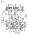
- FIG. 1 is a perspective cross-section of a seatbelt retractor 10.
- the seatbelt retractor 10 has a spool 14 upon which is wound a seatbelt 16.
- the seatbelt retractor 10 allows the belt 16 to protract in the direction of arrow A and to retract in the direction of arrow B.
- the spool 14 rotates in the direction of arrow Z to wind retraction a spring 17.
- a retraction spring 17 rewinds the unused portion of the seatbelt 16 in the direction of arrow B by rotating the spool 14 in the direction of arrow Y.
- the seatbelt retractor 10 has an inertial sensor 19 that detects changes in vehicle speed. In a crash the inertial sensor 19 actuates a pawl (not shown) that engages and locks the locking wheel 21 in place to limit protraction of the seatbelt 16.
- the seatbelt retractor 10 has a torsion bar 18 that absorbs energy from the spool 14 as the seatbelt 16 protracts.
- the torsion bar 18 is mechanically linked to twist and deform with the spool 14.
- the torsion bar 18 has a first portion 22 and a second portion 26.
- the first portion 22 has a thicker diameter than the second portion 26. Both portions 22, 26 are deformable. The twisting of the first portion 22 results in the absorption of energy at a relatively higher rate than the twisting of the second portion 26.
- the torsion bar 18 acts as a support upon which the spool 14 is rotatably mounted.
- An end portion 100 of the torsion bar 18 has splines 24 that engage grooves (not shown) in the locking wheel 21 and is rotationally locked in movement with the locking wheel 21.
- the other end 104 of the torsion bar 18 is rotationally locked in movement with a retraction spring 17.
- a threaded member 50, a torque tube, is disposed around the torsion bar 18.
- the threaded member 50 has grooves (not shown) that engage splines 25 of the first portion 22 of the torsion bar 18 so that the threaded member 50 is rotationally locked in movement with the first portion 22.
- the torsion bar 18 has splines 33 located near an end portion 104 of the second portion 26.
- the splines 33 engage grooves (not shown) in a coupler 54 so that the second portion 26 is rotationally locked in movement with the coupler 54.
- a threaded member 50 has raised portions 108 that engage holes 112 in the coupler 54. The fit between the holes 112 in the coupler 54 and raised portions 108 of the threaded member 50 is tighter than the fit between the splines 33 of the second portion 26 and the grooves in the coupler 54.
- the spool 14 is rotationally locked in movement with the torsion bar 18 through the coupler 54, which, at this point, is engaged with the threaded member 50.
- the threaded member 50 is rotationally locked in movement with a first portion 22 of the torsion bar 18.
- rotation of the spool 14 causes the torsion bar 18 to wind or unwind the retraction spring 17.
- the torsion bar 18 is selectively actuated to absorb energy from the protraction of the seatbelt 16 at two different rates: a relatively high rate through the first portion 22 and a relative low rate through the second portion 26.
- the seatbelt retractor 10 has an additional shift mechanism 30, which selects the rate by which the torsion bar 18 absorbs energy.
- the seatbelt retractor 10 has two features that control energy absorption providing an additional level of control.
- control unit 58 determines the appropriate rate by sensing the size and weight of the vehicle occupant through known sensors and programming. After the control unit 58 has made this determination, it controls the position of coupler 54 based on this sensed data.
- the control unit 58 maintains the seatbelt retractor 10 in the position shown in Figure 2 .
- the coupler 54 is in a position to engage the spool 14 with the first portion 22.
- the inertial sensor 19 locks the locking wheel 21 in place during a crash
- the end portion 100 of the first portion 22 is prevented from rotating.
- Withdrawal of the seatbelt 16 in the direction of arrow A transmits a load along a load path 27, i.e., through the spool 14, the coupler 54, the threaded member 50, and the first portion 22.
- the end portion 100 is locked in place by the locking wheel 21 while, at the splines 25, the first portion 22 will continue to rotate in the direction of arrow Z.
- the first portion 22 will twist at the splines 25 and absorb energy by deforming.
- the torsion bar 18 absorbs energy from the spool 14 entirely through the first portion 22 irrespective of the number of crashes.
- the first portion 22 has sufficient deformability to absorb energy for the anticipated number of crash events.
- control unit 58 determines that a moderate weight vehicle occupant occupies the seat, it is preferable to slow acceleration of the moderate weight vehicle occupant initially at a high rate than at a slow rate. Accordingly, the control unit 58 allows the spool 14 to deform the first portion 22 for a predetermined number of turns or a predetermined amount of time and then moves the coupler 54 along an axis X in the direction of arrow C from a first position 62 shown in Figure 2 to a second position 66 shown in Figure 3 . As shown in Figure 3 the coupler 54 is decoupled from the threaded member 50 but still remains coupled to the spool 14 at the splines 33 of the second portion 26.
- the load path 29 is then formed so that a load is transmitted through the spool 14, the coupler 54, and the splines 33 to a second portion 26 of the torsion bar 18.
- the second portion 26 is locked at the splines 200 to the threaded member 50 and thereby to the first portion 22 of the torsion bar.
- the control unit 58 is programmed to shift the coupler 54 from a position 62 to another position 66 immediately so that the load is transmitted along the load path 29 at once as shown in Figure 3 . In this manner energy is absorbed by the seatbelt retractor 10 only at the lower rate.
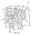
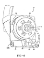
- the control unit 58 is in communication with an actuator 74, a pyrotechnic device which, when actuated, generates a gas in the direction of arrow D.
- Arrow D is transverse to the axis X.
- this gas creates a force 78 on a wall 92 of a member 82.
- the member 82 then rotates about the axis X in the direction of the arrow Y and rides up on a guide structure 86, such as ramps, causing the member 82 to move in the direction of arrow C. Movement of the member 82 causes movement of the coupler 54 in the direction of arrow C.
- the member 82 will tend to slide down the guide structure 86 and separate from the coupler 54. This is desirable because otherwise the coupler 54 and the spool 14 will encounter resistance when the retraction spring 17 rewinds the spool 14. If the actuator 74 is not actuated, the coupler 54 and the member 82 are biased to the bottom of the guide structure 86 by a retaining spring 90.
- Control of the energy absorption rate by the control unit 58 is performed by known programming that analyzes the weight and size of the vehicle occupant.
- the seatbelt retractor 10 has a shift mechanism 30 for shifting between a first portion 22 and a second portion 26. In contrast to the control unit 58, the shift mechanism 30 shifts the seatbelt retractor 10 without reference to the weight or size of the vehicle occupant.
- the torsion bar 18 has a threaded member 50 that is linked in rotation with the first portion 22 at the splines 25.
- the threaded member 50 When the torsion bar 18 rotates along the direction of arrow Z as the seatbelt 16 protracts the threaded member 50 also rotates.
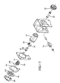
- Received on the threaded member 50 is a shift mechanism 30, in this case threaded movable links or runners (see Figure 7 ).
- the shift mechanism 30 is linked in rotation with the spool 14 while a threaded member 50 is linked in rotation with the torsion bar 18. Because the torsion bar 18 deforms, the threaded member 50 will rotate at a slower rate than the spool 14, creating relative motion between the spool 14 and the threaded member 50.
- this relative motion between the threaded member 50 and the spool 14 causes the shift mechanism 30 to rotate about the threads of the threaded member 50 and thereby to move in the direction of arrow C from a first link position 34 to a second link position 38.
- the shift mechanism 30 will abut an end portion 39 of the threaded member 50.
- the shift mechanism 30 can no longer move in the direction of arrow C.
- the load from the seatbelt protraction will then be transmitted along a load path 31 through the spool 14, the shift mechanism 30, the threaded member 50 and a first portion 22 of torsion bar 18.
- the torsion bar 18 will now absorb energy from the spool 14 at a higher rate than the second portion 26.
- the shift mechanism 30 shifts automatically and mechanically from a low rate to a high rate of energy absorption. When this shift occurs depends upon the number of turns the spool 14 is allowed to rotate before the shift mechanism 30 abuts the end portion 39. The number of turns may be based on the anticipated location of the vehicle occupant following airbag deployment. If a second crash occurs the seatbelt retractor 10 is ready to absorb a second impact at a high rate of energy absorption.
- the control unit 58 allows the first portion 22 to absorb energy from the spool 14 at a high rate, then shifts the coupler 54 from the first coupling position 62 to the second coupling position 66 to allow energy to be absorbed by the second portion 26 at a low rate. Following a predetermined number of turns the shift mechanism 30 shifts back to the high rate of first portion 22. For a light weight vehicle occupant the control unit 58 shifts immediately to a low rate of energy absorption. After a predetermined number of turns the shift mechanism 30 shifts to the high rate of energy absorption. Both the middleweight and the lightweight vehicle occupants are protected in a second crash.
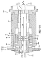
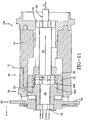
- FIGs 8 through 14 an alternative seatbelt retractor 10A is shown.
- the seatbelt retractor 10A has all the components shown in the retractor 10 illustrated and described with respect to Figures 1 - 7 except that the threaded member 50 is replaced by an outer sheath component 50A.
- the outer sheath 50A as illustrated is die-cast onto the torsion bar 18.
- the torsion bar 18 is mechanically linked to twist and deform with the spool 14.
- the torsion bar 18 has a first portion 22 and a second portion 26.
- the first portion 22 has a larger diameter than the second portion 26 - both portions 22, 26 are deformable. Twisting of the first portion 22 results in the absorption of energy at a relatively higher rate than the twisting of the second portion 26, which absorbs energy at a relatively low rate.
- the torsion bar 18 acts as a support upon which the spool 14 is rotatably mounted.
- One end portion 100 of the torsion bar 18 has splines 25 that engage grooves (not shown) in the locking wheel 21 and is thereby rotationally locked in movement with the locking wheel 21.
- the other end 104 of the torsion bar 18 is rotationally coupled to a retraction spring 17.
- the outer sheath 50A like the threaded member 50, forms a torque tube disposed around the torsion bar 18.
- the outer sheath 50A as with the threaded member 50 has exterior threads.
- the sheath 50A will be formed with grooves (not shown) that by virtue of being cast about the splines 25 of first portion 22 of the torsion bar 18 so that the sheath 50A is rotationally locked in movement with the first portion 22.
- the torsion bar 18 has splines 33 located near an end portion 104 of the second portion 26. These splines 33 engage the grooves (not shown) in the coupler 54 so that the second portion 26 is rotationally locked in movement with the coupler 54.
- the sheath 50A has raised or projecting portions 108 that engage holes 112 in coupler 54. The fit between the holes 112 in the coupler 54 and raised portions 108 of the sheath 50A is tighter than the fit between the splines 33 of second portion 26 and the grooves in the coupler 54.
- the torsion bar 18 is selectively actuated to absorb energy from the protraction of the seatbelt 16 at two different rates: a relatively high rate through the first portion 22 and a relative low rate through the second portion 26.
- the seatbelt retractor 10A has an additional shift mechanism 30, which selects the rate at which the torsion bar 18 absorbs energy.
- the seatbelt retractor 10A has two features that control energy absorption thereby providing an additional level of control not found in other seatbelt retractors.
- the operation of the seatbelt retractor 10A is the same as previously described with respect to Figures 1-7 , with the exception of the threaded member 50 was mechanically crimped onto the torsion bar 18 whereas the outer sheath 50A as shown was die-cast onto the torsion bar.
- the retractor 10A with the outer sheath 50A shown in Figures 8-14 functions like the retractor 10 with the crimped on mechanically attached threaded member 50 with a improved the performance.
- the outer sheath 50A is a die-cast part formed directly onto the torsion bars 22, 26.
- the torsion bars 22, 26 are made of steel alloyed and formed to twist multiple times before yielding or breaking.
- the outer sheath 50A as shown is made of zinc that at the underlying surface interfaces with the steel torsion bar 22, 26 created a bond capable of resisting a twisting torque up to a point. Beyond this threshold torque the bond quickly and uniformly breaks along its weakest attachment location. For example in the torsion bar 26 of a smaller diameter as the torque is applied and a load is transmitted to the second portion 26 the outer sheath 50A continues to transfer the torque to the larger diameter portion 22.
- the load absorption rate will be at the high rate until the bond along the shaft of the portion 26 fails at the interface.
- the bond of the outer sheath 50A fails and lets go quickly and uniformly as a function of the circumferential area bonded along the smaller diameter shaft of portion 26 thereafter the retractor drops almost instantaneously to low rate of energy absorption from the pre bond breaking higher rate.
- This subtle change means the seatbelt payout load transitions from a high load rate to a low load rate more quickly than by the prior mechanical grip method. This is illustrated in Figure 16c .
- the outer sheath can be any suitable die-cast material like zinc, 14K gold or a zinc alloy or a molded plastic or composite material wherein the torsion bar is inserted into the outer sheath or the sheath material may be a coated material applied to the surface of a portion of the torsion bar.
- the breaking of the bond between the surface of the torsion bar and the outer sheath provides an improved rapid transition from a higher energy absorption level to a lower energy absorption level through the elastic-plastic deformation regions of the loaded torsion members when compared to conventional torsion bars.
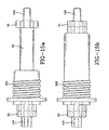
- a die-cast outer sheath 50A can be used on a single torsion bar of a uniform diameter as shown in Figures 15a and 15b .
- the outer sheath covers a portion of the torsion bar twist shaft whereas in Figure 15b the outer sheath is shown extending across the entire length of the twist shaft of the torsion bar.
- one large diameter shaft portion 22 and a second smaller diameter shaft portion 26 of the outer sheath 50A can be used.
- the outer sheath 50A can be applied on the torsion bars as a coating, molded onto the underlying torsion bars or cast onto the torsion bars.
- the primary criteria is that a bond is created at the surface interface that can withstand a torque or load higher than at least a portion of the underlying torsion bar as the torsion bar twists it elongates and the diameter narrows such that when the torque twist reaches and therefore starts to exceed the strength of the bond at least a portion of the bond breaks such that the rate of energy absorptions drop quickly making a more rapid transition to the desired rate of energy absorption.
- the outer sheath 50A breaks the bond across the entire surface interface with the outer sheath 50A and the underlying torsion bar.
- the coating, casting, or molded outer sheath 50A must be sufficiently strong to insure it transfers the loads to break the bond surface are in its entirety on the torsion bar wherein the energy absorption load to be absorbed. This insures the transfer of load rates is virtually instantaneous in a crash.
- the die-cast outer sheath 50A was made of zinc, but could be any zinc alloy or suitable die-cast material.
- the die-cast outer sheath 50 could alternatively be insert molded into a plastic or composite or resin based polymer outer sheath to achieve a bond sufficient for the purposes.
- a thick coating could be made of epoxy resin or a similar material to form the outer sheath 50A.
Landscapes
- Engineering & Computer Science (AREA)
- Mechanical Engineering (AREA)
- Automotive Seat Belt Assembly (AREA)
Claims (9)
- Enrouleur de ceinture de sécurité (10), comprenant :une bobine (14) pouvant tourner sur un axe ;une barre de torsion (18), s'étendant le long de l'axe et supportant la bobine (14), la barre de torsion (18) comportant une première partie (22) pour fournir une force relativement élevée, afin de résister à un déroulement de la ceinture de sécurité, et une deuxième partie (26) pour fournir une force relativement réduite, afin de résister à un déroulement de la ceinture de sécurité par rapport à la bobine (14) ; etune gaine externe (50A) agencée entre la bobine (14) et la barre de torsion (18), la gaine externe (50A) étant coulée sous pression, moulée, revêtue ou reliée d'une autre manière aux première et deuxième parties (22, 26) de la barre de torsion, le long de parties des surfaces externes de la barre de torsion (18) ; séparant, lors d'une exposition suffisante à l'énergie de rotation, la liaison entre la barre de torsion (18) le long de la deuxième partie de la gaine externe (50A).
- Enrouleur de ceinture de sécurité (10) selon la revendication 1, englobant un moyen d'accouplement (54), destiné à engager sélectivement la première partie (22) de la barre de torsion (18) et la deuxième partie (26) de la barre de torsion (18) dans la bobine (14), le moyen d'accouplement (54) comportant une première position d'accouplement, dans laquelle la première partie (22) de la barre de torsion est engagée dans la bobine (14), et comportant une deuxième position d'accouplement, dans laquelle la deuxième partie (26) de la barre de torsion (18) est engagée dans la bobine (14), le moyen d'accouplement (54) étant agencé de sorte à se déplacer entre la première position d'accouplement et la deuxième position d'accouplement, dans une direction s'étendant en général le long de l'axe.
- Enrouleur de ceinture de sécurité (10) selon la revendication 2, englobant un moyen d'actionnement (74) pour déplacer le moyen d'accouplement (54) entre la première position d'accouplement et la deuxième position d'accouplement.
- Enrouleur de ceinture de sécurité (10) selon la revendication 3, dans lequel le moyen d'actionnement (74) est un générateur de gaz.
- Enrouleur de ceinture de sécurité (10) selon les revendications 3 ou 4, dans lequel le moyen d'actionnement (74) est agencé de sorte à diriger une force d'actionnement dans une direction transversale à l'axe, la force d'actionnement servant à déplacer le moyen d'accouplement (54) entre la première position d'accouplement et la deuxième position d'accouplement.
- Enrouleur de ceinture de sécurité (10) selon l'une quelconque des revendications 3 à 5, englobant un élément (86) pour rediriger la force d'actionnement de la direction transversale à l'axe vers une direction s'étendant en général le long de l'axe.
- Enrouleur de ceinture de sécurité (10) selon la revendication 6, englobant une structure de guidage (86) pour rediriger l'élément.
- Enrouleur de ceinture de sécurité (10) selon la revendication 7, dans lequel la structure de guidage (86) est une rampe.
- Enrouleur de ceinture de sécurité (10) selon l'une quelconque des revendications 2 à 8, comprenant en outre un mécanisme de décalage (30) pour établir un décalage entre la première partie et la deuxième partie, le mécanisme de décalage (30) comprenant un élément de liaison (50) pouvant être déplacé entre une première position de liaison, dans laquelle la première partie (22) de la barre de torsion (18) s'engage dans la bobine (14), et une deuxième position de liaison, dans laquelle la deuxième partie (26) de la barre de torsion (18) s'engage dans la bobine (14).
Applications Claiming Priority (2)
| Application Number | Priority Date | Filing Date | Title |
|---|---|---|---|
| US11/560,465 US7669794B2 (en) | 2004-09-01 | 2006-11-16 | Seatbelt retractor with torsion bar |
| PCT/US2007/013667 WO2008060337A1 (fr) | 2006-11-16 | 2007-06-08 | Rétracteur de ceinture de sécurité avec barre de torsion |
Publications (3)
| Publication Number | Publication Date |
|---|---|
| EP2089256A1 EP2089256A1 (fr) | 2009-08-19 |
| EP2089256A4 EP2089256A4 (fr) | 2010-03-10 |
| EP2089256B1 true EP2089256B1 (fr) | 2010-10-20 |
Family
ID=39401971
Family Applications (1)
| Application Number | Title | Priority Date | Filing Date |
|---|---|---|---|
| EP07795963A Not-in-force EP2089256B1 (fr) | 2006-11-16 | 2007-06-08 | Retracteur de ceinture de securite avec barre de torsion |
Country Status (9)
| Country | Link |
|---|---|
| US (1) | US7669794B2 (fr) |
| EP (1) | EP2089256B1 (fr) |
| JP (1) | JP4814379B2 (fr) |
| KR (1) | KR20090074076A (fr) |
| CN (1) | CN101535096B (fr) |
| AT (1) | ATE485197T1 (fr) |
| DE (1) | DE602007010021D1 (fr) |
| ES (1) | ES2352699T3 (fr) |
| WO (1) | WO2008060337A1 (fr) |
Families Citing this family (53)
| Publication number | Priority date | Publication date | Assignee | Title |
|---|---|---|---|---|
| JP2006159969A (ja) * | 2004-12-02 | 2006-06-22 | Tkj Kk | シートベルトリトラクタ、シートベルト装置、シートベルト装置付車両 |
| US7263750B2 (en) | 2005-06-09 | 2007-09-04 | Amsafe, Inc. | Buckle assembly having single release for multiple belt connectors |
| WO2009045132A1 (fr) * | 2007-10-05 | 2009-04-09 | Autoliv Development Ab | Rétracteur adaptatif de ceinture de sécurité de limitation de charge |
| JP4922966B2 (ja) * | 2008-03-05 | 2012-04-25 | オートリブ ディベロップメント エービー | シートベルト用リトラクタ |
| JP4922967B2 (ja) * | 2008-03-05 | 2012-04-25 | オートリブ ディベロップメント エービー | シートベルト用リトラクタ |
| WO2010037103A1 (fr) | 2008-09-29 | 2010-04-01 | Amsafe, Inc. | Dispositifs de mise en tension destinés à des systèmes de ceintures de sécurité pour occupants d'un véhicule, et systèmes et procédés associés |
| US8469401B2 (en) | 2009-02-23 | 2013-06-25 | Amsafe, Inc. | Seat harness pretensioner |
| DE102009024292B4 (de) * | 2009-06-05 | 2014-10-09 | Autoliv Development Ab | Gurtaufroller für einen Sicherheitsgurt eines Kraftfahrzeuges |
| US8393645B2 (en) | 2009-11-02 | 2013-03-12 | Amsafe Commercial Products, Inc. | Devices for adjusting tension in seat belts and other restraint system webs, and associated methods |
| US8683666B2 (en) | 2009-11-04 | 2014-04-01 | Amsafe Commercial Products, Inc. | Restraint system buckle components having tactile surfaces, and associated methods of use and manufacture |
| US8220735B2 (en) * | 2009-12-22 | 2012-07-17 | Autoliv Asp, Inc. | Adaptive load limiting retractor |
| US8627554B1 (en) | 2010-05-03 | 2014-01-14 | Amsafe, Inc. (Phoenix Group) | Buckle assemblies with swivel and dual release features and associated methods of use and manufacture |
| US8777323B2 (en) | 2010-07-20 | 2014-07-15 | Amsafe, Inc. | Restraint harnesses and associated methods of use and manufacture |
| JP5449075B2 (ja) * | 2010-07-27 | 2014-03-19 | 株式会社東海理化電機製作所 | ウェビング巻取装置 |
| JP2012030636A (ja) * | 2010-07-29 | 2012-02-16 | Takata Corp | シートベルトリトラクタおよびこれを用いたシートベルト装置 |
| DE102010036092B4 (de) * | 2010-08-27 | 2017-10-12 | Illinois Tool Works, Inc. | Sicherheitsgurteinrichtung |
| USD655223S1 (en) | 2010-09-15 | 2012-03-06 | Amsafe Commercial Products, Inc. | Buckle assembly |
| USD661619S1 (en) | 2010-09-15 | 2012-06-12 | Amsafe Commercial Products, Inc. | Buckle assembly |
| JP5676283B2 (ja) * | 2011-01-11 | 2015-02-25 | 株式会社東海理化電機製作所 | ウェビング巻取装置 |
| KR101284239B1 (ko) | 2011-02-21 | 2013-07-09 | 주식회사 디비아이 | 로드 리미터 |
| DE102011012856A1 (de) * | 2011-03-02 | 2012-09-06 | Trw Automotive Gmbh | Gurtaufroller für einen Sicherheitsgurt |
| JP5843651B2 (ja) * | 2012-02-17 | 2016-01-13 | タカタ株式会社 | シートベルトリトラクタおよびこれを備えているシートベルト装置 |
| JP2013184605A (ja) * | 2012-03-08 | 2013-09-19 | Tokai Rika Co Ltd | ウェビング巻取装置 |
| JP2013193504A (ja) * | 2012-03-16 | 2013-09-30 | Tokai Rika Co Ltd | ウェビング巻取装置 |
| US9022483B2 (en) | 2012-06-07 | 2015-05-05 | Shield Restraint Systems, Inc. | Seatbelt buckle tongue assembly |
| DE102012107557B3 (de) | 2012-08-17 | 2014-10-30 | Autoliv Development Ab | Gurtaufroller mit einer schaltbaren Kraftbegrenzungseinrichtung |
| EP2889191B1 (fr) * | 2012-08-27 | 2019-10-02 | Helia Technology Limited | Rétracteur pour ceinture de sécurité, barre de torsion, enrouleur, embout et ensemble ceinture de sécurité |
| CN102837664B (zh) * | 2012-08-27 | 2016-01-13 | 上海和励信息科技有限公司 | 一种用于安全带的卷收器和安全带总成 |
| KR101477610B1 (ko) * | 2013-01-30 | 2014-12-31 | 주식회사 우신세이프티시스템 | 제한 하중의 선택적 조절이 가능한 로드 리미터 및 이를 포함하는 리트랙터 |
| EP2958453A4 (fr) | 2013-02-19 | 2016-07-27 | Amsafe Inc | Ensembles boucles à leviers de blocage à soulèvement, et procédés et systèmes associés |
| US9277788B2 (en) | 2013-02-19 | 2016-03-08 | Amsafe, Inc. | Dual release buckle assemblies and associated systems and methods |
| US9168890B1 (en) | 2014-09-03 | 2015-10-27 | Ford Global Technologies, Llc | Seat belt retractor with wedge clamp and load limiter |
| US10196034B2 (en) | 2014-10-22 | 2019-02-05 | Autoliv Development Ab | Seat belt retractor |
| WO2016100566A1 (fr) | 2014-12-16 | 2016-06-23 | Shield Restraint Systems, Inc. | Dispositifs de réglage de bande pour l'utilisation avec des systèmes de maintien et procédés associés d'utilisation et de fabrication |
| US10604259B2 (en) | 2016-01-20 | 2020-03-31 | Amsafe, Inc. | Occupant restraint systems having extending restraints, and associated systems and methods |
| US9814282B2 (en) | 2016-02-02 | 2017-11-14 | Shield Restraint Systems, Inc. | Harsh environment buckle assemblies and associated systems and methods |
| CN109153369B (zh) * | 2016-04-06 | 2021-05-07 | Trw汽车股份有限公司 | 用于释放用于车辆安全带的安全带卷收器的力限制器的执行机构以及具有这种执行机构的安全带卷收器 |
| CN109153368B (zh) * | 2016-04-06 | 2021-08-27 | Trw汽车股份有限公司 | 具有第二力限制器的安全带卷收器 |
| CN108238001A (zh) * | 2016-12-26 | 2018-07-03 | 和励科技有限公司 | 用于安全带卷收器的扭力杆、安全带卷收器及安全带总成 |
| US10611334B2 (en) | 2017-02-07 | 2020-04-07 | Shield Restraint Systems, Inc. | Web adjuster |
| US10399540B2 (en) * | 2017-03-28 | 2019-09-03 | Joyson Safety Systems Acquisition Llc | Seat belt retractor with energy absorbing mechanism |
| DE102019107663A1 (de) * | 2018-07-26 | 2020-01-30 | Autoliv Development Ab | Kraftbegrenzungseinrichtung aufweisender Gurtaufroller mit Entkopplungseinrichtung |
| JP7151364B2 (ja) * | 2018-10-17 | 2022-10-12 | Joyson Safety Systems Japan株式会社 | シートベルトリトラクタ |
| US10836347B2 (en) * | 2018-12-21 | 2020-11-17 | Joyson Safety Systems Acquisition Llc | Seat belt retractor |
| US11014529B2 (en) * | 2019-04-30 | 2021-05-25 | Joyson Safety Systems Acquisition Llc | Seat belt retractor |
| DE202019106965U1 (de) * | 2019-12-13 | 2021-03-16 | Igus Gmbh | Aufwickeltrommel und Torsionsfeder für eine Aufwickeltrommel |
| US11577685B2 (en) | 2020-06-03 | 2023-02-14 | Jean Alain van Poppel | Adaptive load-limiting seatbelt assembly |
| US11970131B2 (en) | 2022-02-28 | 2024-04-30 | Ford Global Technologies, Llc | Load limiting seatbelt retractor |
| USD1062408S1 (en) * | 2022-09-15 | 2025-02-18 | Chin-Sung Huang | Ratchet gear for a seat belt adjuster |
| WO2024101057A1 (fr) * | 2022-11-08 | 2024-05-16 | オートリブ ディベロップメント エービー | Rétracteur de ceinture de sécurité |
| US12263807B2 (en) | 2022-12-08 | 2025-04-01 | Jean Alain van Poppel | Adaptive load-limiting seatbelt assembly |
| US12221059B2 (en) * | 2023-05-16 | 2025-02-11 | Ford Global Technologies, Llc | Load-limiting seatbelt retractor |
| KR102921606B1 (ko) * | 2023-10-16 | 2026-02-02 | 아우토리브 디벨롭먼트 아베 | 부하 조절 모듈이 적용된 시트벨트 리트랙터 |
Family Cites Families (52)
| Publication number | Priority date | Publication date | Assignee | Title |
|---|---|---|---|---|
| US1335807A (en) | 1919-04-11 | 1920-04-06 | John Macdonald & Son Ltd | Support for pneumatic tools |
| USRE29147E (en) | 1970-05-29 | 1977-03-08 | Repa Feinstanzwerk Gmbh | Energy absorber for automobile safety belts |
| DE7306883U (de) | 1972-03-30 | 1973-05-30 | Ford Werke Ag | Aufrolleinrichtung für Sicherheitsgurte , insbesondere für Kraftfahrzeuge |
| DE2222742C3 (de) | 1972-05-09 | 1974-09-26 | Klink, Wolf-Dieter, 7071 Lindach | Energiewandler für Sicherheitsgurte |
| IT1014283B (it) | 1974-06-04 | 1977-04-20 | Fiat Spa | Dissipatore di energia per cinture di sicurezza di autoveicoli |
| DE2727470A1 (de) | 1977-06-18 | 1979-01-04 | Volkswagenwerk Ag | Sicherheitsgurteinrichtung fuer fahrzeuge, insbesondere kraftfahrzeuge |
| JPS5619245U (fr) | 1979-07-19 | 1981-02-20 | ||
| DE4432594A1 (de) | 1994-09-13 | 1996-03-14 | Takata Europ Gmbh | Gurtstraffer bei Sicherheitsgurtanordnungen in Kraftfahrzeugen |
| DE4436810C2 (de) | 1994-10-14 | 1998-12-24 | Hs Tech & Design | Gurtaufroller für einen Sicherheitsgurt eines Kraftfahrzeugs |
| US5511739A (en) | 1994-11-28 | 1996-04-30 | Alliedsignal Inc. | Retractor having a single sided energy absorbing spool |
| US5558295A (en) | 1994-12-20 | 1996-09-24 | Trw Vehicle Safety Systems Inc. | Seat belt retractor with automatic locking mechanism |
| DE19681341C1 (de) * | 1995-04-14 | 2002-08-01 | Autoliv Dev | Gurtaufroller mit abgedämpftem Kraftbegrenzer |
| US5607118A (en) | 1995-08-11 | 1997-03-04 | Alliedsignal Inc. | Retractor with adjustable load limiting levels |
| US5611498A (en) | 1995-08-11 | 1997-03-18 | Alliedsignal Inc. | Seat belt retractor with auxiliary shaft load limiting |
| US5671894A (en) | 1995-08-11 | 1997-09-30 | Alliedsignal Inc. | Retractor with load limiting spool with decoupled pretensioner |
| US5626306A (en) | 1995-08-11 | 1997-05-06 | Alliedsignal Inc. | Multiple level load limiter for primary and secondary collisions |
| DE19544918A1 (de) | 1995-12-01 | 1997-06-05 | Icsrd Rueckhaltesysteme Fuer F | Sicherheitsgurtaufroller |
| DE19546731A1 (de) | 1995-12-14 | 1997-06-19 | Daimler Benz Ag | Gurtroller für einen Sicherheitsgurt |
| US5618006A (en) | 1996-02-23 | 1997-04-08 | Trw Vehicle Safety Systems Inc. | Seat belt retractor with energy management |
| BR9709962A (pt) | 1996-06-26 | 1999-08-10 | Autoliv Dev | Dispositivo enrolador de cinta com dispositivo de limitação de força ajustável |
| US5823570A (en) | 1996-10-10 | 1998-10-20 | Trw Vehicle Safety Systems Inc. | Seat belt retractor with energy management |
| US5785269A (en) * | 1997-02-06 | 1998-07-28 | Alliedsignal Inc. | Dual level retractor for oblique or offset impacts |
| US5820056A (en) | 1997-02-06 | 1998-10-13 | Alliedsignal Inc. | Retractor with load limiting spool |
| US5799893A (en) | 1997-02-19 | 1998-09-01 | Alliedsignal Inc. | Multi-level load limiting torsion bar retractor |
| US5788177A (en) | 1997-02-21 | 1998-08-04 | Alliedsignal Inc. | Multi-level load limiting retractor |
| US5830811A (en) | 1997-03-18 | 1998-11-03 | Alliedsignal Inc. | Load leveling yarns and webbings |
| DE19727919C2 (de) | 1997-05-15 | 2000-03-09 | Autoliv Dev | Gurtaufroller mit zu- oder abschaltbarer Kraftbegrenzungseinrichtung |
| US5967441A (en) | 1997-07-22 | 1999-10-19 | Breed Automotive Technology, Inc. | Seat belt retractor with torsion bar and rotation limit |
| DE19733787C1 (de) | 1997-08-05 | 1998-12-03 | Daimler Benz Ag | Gurtroller für ein Sicherheitsgurtsystem eines Personensitzes |
| US5842657A (en) | 1997-08-15 | 1998-12-01 | Trw Inc. | Seat belt webbing pretensioner |
| US6012667A (en) * | 1998-02-19 | 2000-01-11 | Breed Automotive Technology Inc. | Multi-level load limiting torsion bar retractor |
| US5904371A (en) | 1998-02-19 | 1999-05-18 | Breed Automotive Technology, Inc. | Energy management safety belt retractor with mode shifting mechanism |
| JP3775046B2 (ja) * | 1998-04-01 | 2006-05-17 | タカタ株式会社 | シートベルト装置及び車両 |
| US5899402A (en) | 1998-04-14 | 1999-05-04 | Breed Automotive Technology, Inc. | Torsion bar with sharp, rapid onset property and retractor |
| US6228488B1 (en) | 1998-05-22 | 2001-05-08 | Alliedsignal Inc. | Process for making load limiting yarn |
| ES2188058T3 (es) | 1998-06-04 | 2003-06-16 | Trw Repa Gmbh | Conjunto que comprende al menos dos barras de tension para limitar la fuerza en un enrollador de cinturon. |
| DE19856364A1 (de) | 1998-12-07 | 2000-06-08 | Trw Repa Gmbh | Gurtaufroller für einen Fahrzeugsicherheitsgurt |
| DE29821801U1 (de) | 1998-12-07 | 1999-04-08 | TRW Occupant Restraint Systems GmbH & Co. KG, 73553 Alfdorf | Gurtaufroller für einen Fahrzeug-Sicherheitsgurt |
| DE19902483C2 (de) | 1999-01-22 | 2001-12-13 | Breed Automotive Tech | Sicherheitsgurtaufroller |
| EP1178906B1 (fr) | 1999-05-20 | 2004-05-12 | Breed Automotive Technology, Inc. | Dispositif de rappel de ceinture de securite |
| DE19927427C2 (de) | 1999-06-16 | 2002-11-14 | Autoliv Dev | Gurtaufroller mit schaltbarem Kraftbegrenzer |
| DE19957814C2 (de) | 1999-12-01 | 2003-07-31 | Trw Automotive Electron & Comp | Gurtaufrollersystem |
| US20020092943A1 (en) * | 2000-07-14 | 2002-07-18 | Breed Automotive Technology, Inc. | Energy absorbing seat belt retractor |
| JP4357721B2 (ja) * | 2000-08-21 | 2009-11-04 | オートリブ株式会社 | シートベルト装置 |
| DE20019468U1 (de) | 2000-11-16 | 2001-03-29 | TRW Occupant Restraint Systems GmbH & Co. KG, 73553 Alfdorf | Gurtaufroller für einen Fahrzeug-Sicherheitsgurt |
| JP4721387B2 (ja) * | 2000-12-08 | 2011-07-13 | タカタ株式会社 | シートベルトリトラクタ |
| GB2371780A (en) | 2001-02-06 | 2002-08-07 | Autoliv Dev | A safety-belt arrangement |
| US6648260B2 (en) | 2001-07-25 | 2003-11-18 | Delphi Technologies, Inc. | Selectable load limiting seat restraint retractor |
| US6685124B2 (en) | 2001-11-30 | 2004-02-03 | Trw Vehicle Safety Systems Inc. | Seat belt pretensioner with brake |
| US6863235B2 (en) | 2002-01-17 | 2005-03-08 | Key Safety Systems, Inc. | Mechanical shifting of multi-load retractor |
| US7240924B2 (en) * | 2004-07-29 | 2007-07-10 | Key Safety Systems, Inc. | Multilevel load limiting retractor with dual shifting mode |
| US20060131456A1 (en) * | 2004-12-21 | 2006-06-22 | Takata Seat Belts, Inc. | Retractor with multiple level load limiter |
-
2006
- 2006-11-16 US US11/560,465 patent/US7669794B2/en not_active Expired - Fee Related
-
2007
- 2007-06-08 CN CN2007800420307A patent/CN101535096B/zh not_active Expired - Fee Related
- 2007-06-08 DE DE602007010021T patent/DE602007010021D1/de active Active
- 2007-06-08 EP EP07795963A patent/EP2089256B1/fr not_active Not-in-force
- 2007-06-08 WO PCT/US2007/013667 patent/WO2008060337A1/fr not_active Ceased
- 2007-06-08 ES ES07795963T patent/ES2352699T3/es active Active
- 2007-06-08 JP JP2009535260A patent/JP4814379B2/ja active Active
- 2007-06-08 KR KR1020097009915A patent/KR20090074076A/ko not_active Ceased
- 2007-06-08 AT AT07795963T patent/ATE485197T1/de not_active IP Right Cessation
Also Published As
| Publication number | Publication date |
|---|---|
| CN101535096A (zh) | 2009-09-16 |
| US7669794B2 (en) | 2010-03-02 |
| EP2089256A4 (fr) | 2010-03-10 |
| US20070075173A1 (en) | 2007-04-05 |
| EP2089256A1 (fr) | 2009-08-19 |
| WO2008060337A1 (fr) | 2008-05-22 |
| CN101535096B (zh) | 2012-02-29 |
| JP2010508205A (ja) | 2010-03-18 |
| KR20090074076A (ko) | 2009-07-03 |
| JP4814379B2 (ja) | 2011-11-16 |
| DE602007010021D1 (de) | 2010-12-02 |
| ATE485197T1 (de) | 2010-11-15 |
| ES2352699T3 (es) | 2011-02-22 |
Similar Documents
| Publication | Publication Date | Title |
|---|---|---|
| EP2089256B1 (fr) | Retracteur de ceinture de securite avec barre de torsion | |
| US7240924B2 (en) | Multilevel load limiting retractor with dual shifting mode | |
| JP4153430B2 (ja) | 複数のレベルで負荷を制限する、シートベルトの巻き取り装置 | |
| US7025297B2 (en) | Seat belt retractor | |
| EP1867533B1 (fr) | Rétracteur de ceinture de sécurité et appareil de ceinture de sécurité l'utilisant | |
| US6669133B2 (en) | Seat belt retractor with multi-level load limiting | |
| EP1918165B1 (fr) | Rétracteur de ceinture de sécurité et son appareil de ceinture de sécurité | |
| JP2002503586A (ja) | 荷重制限シートベルトレトラクタ | |
| US7878439B2 (en) | Retractor with pretensioner for auxiliary load limitation | |
| US9079565B2 (en) | Progressive load limiting restraint system | |
| WO2004033249A2 (fr) | Retracteur de ceinture de securite | |
| US7581757B2 (en) | Retractor with pretensioner | |
| US20070024045A1 (en) | Torsion bar load limiter and pretensioner for seat belt system | |
| EP1494896B1 (fr) | Enrouleur de ceinture de securite | |
| EP1670665B1 (fr) | Dispositif de securite |
Legal Events
| Date | Code | Title | Description |
|---|---|---|---|
| PUAI | Public reference made under article 153(3) epc to a published international application that has entered the european phase |
Free format text: ORIGINAL CODE: 0009012 |
|
| 17P | Request for examination filed |
Effective date: 20090506 |
|
| AK | Designated contracting states |
Kind code of ref document: A1 Designated state(s): AT BE BG CH CY CZ DE DK EE ES FI FR GB GR HU IE IS IT LI LT LU LV MC MT NL PL PT RO SE SI SK TR |
|
| RIN1 | Information on inventor provided before grant (corrected) |
Inventor name: KOHLNDORFER, KENNETH Inventor name: JUNG, MARC A. Inventor name: KONING, RICHARD Inventor name: BOELSTLER, RICHARD |
|
| DAX | Request for extension of the european patent (deleted) | ||
| A4 | Supplementary search report drawn up and despatched |
Effective date: 20100204 |
|
| GRAP | Despatch of communication of intention to grant a patent |
Free format text: ORIGINAL CODE: EPIDOSNIGR1 |
|
| GRAS | Grant fee paid |
Free format text: ORIGINAL CODE: EPIDOSNIGR3 |
|
| GRAA | (expected) grant |
Free format text: ORIGINAL CODE: 0009210 |
|
| AK | Designated contracting states |
Kind code of ref document: B1 Designated state(s): AT BE BG CH CY CZ DE DK EE ES FI FR GB GR HU IE IS IT LI LT LU LV MC MT NL PL PT RO SE SI SK TR |
|
| REG | Reference to a national code |
Ref country code: GB Ref legal event code: FG4D |
|
| REG | Reference to a national code |
Ref country code: CH Ref legal event code: EP |
|
| REG | Reference to a national code |
Ref country code: IE Ref legal event code: FG4D |
|
| REF | Corresponds to: |
Ref document number: 602007010021 Country of ref document: DE Date of ref document: 20101202 Kind code of ref document: P |
|
| REG | Reference to a national code |
Ref country code: RO Ref legal event code: EPE |
|
| REG | Reference to a national code |
Ref country code: ES Ref legal event code: FG2A Effective date: 20110210 |
|
| REG | Reference to a national code |
Ref country code: NL Ref legal event code: VDEP Effective date: 20101020 |
|
| LTIE | Lt: invalidation of european patent or patent extension |
Effective date: 20101020 |
|
| PG25 | Lapsed in a contracting state [announced via postgrant information from national office to epo] |
Ref country code: LT Free format text: LAPSE BECAUSE OF FAILURE TO SUBMIT A TRANSLATION OF THE DESCRIPTION OR TO PAY THE FEE WITHIN THE PRESCRIBED TIME-LIMIT Effective date: 20101020 |
|
| PG25 | Lapsed in a contracting state [announced via postgrant information from national office to epo] |
Ref country code: PT Free format text: LAPSE BECAUSE OF FAILURE TO SUBMIT A TRANSLATION OF THE DESCRIPTION OR TO PAY THE FEE WITHIN THE PRESCRIBED TIME-LIMIT Effective date: 20110221 Ref country code: LV Free format text: LAPSE BECAUSE OF FAILURE TO SUBMIT A TRANSLATION OF THE DESCRIPTION OR TO PAY THE FEE WITHIN THE PRESCRIBED TIME-LIMIT Effective date: 20101020 Ref country code: IS Free format text: LAPSE BECAUSE OF FAILURE TO SUBMIT A TRANSLATION OF THE DESCRIPTION OR TO PAY THE FEE WITHIN THE PRESCRIBED TIME-LIMIT Effective date: 20110220 Ref country code: SI Free format text: LAPSE BECAUSE OF FAILURE TO SUBMIT A TRANSLATION OF THE DESCRIPTION OR TO PAY THE FEE WITHIN THE PRESCRIBED TIME-LIMIT Effective date: 20101020 Ref country code: AT Free format text: LAPSE BECAUSE OF FAILURE TO SUBMIT A TRANSLATION OF THE DESCRIPTION OR TO PAY THE FEE WITHIN THE PRESCRIBED TIME-LIMIT Effective date: 20101020 Ref country code: BG Free format text: LAPSE BECAUSE OF FAILURE TO SUBMIT A TRANSLATION OF THE DESCRIPTION OR TO PAY THE FEE WITHIN THE PRESCRIBED TIME-LIMIT Effective date: 20110120 Ref country code: NL Free format text: LAPSE BECAUSE OF FAILURE TO SUBMIT A TRANSLATION OF THE DESCRIPTION OR TO PAY THE FEE WITHIN THE PRESCRIBED TIME-LIMIT Effective date: 20101020 Ref country code: SE Free format text: LAPSE BECAUSE OF FAILURE TO SUBMIT A TRANSLATION OF THE DESCRIPTION OR TO PAY THE FEE WITHIN THE PRESCRIBED TIME-LIMIT Effective date: 20101020 Ref country code: FI Free format text: LAPSE BECAUSE OF FAILURE TO SUBMIT A TRANSLATION OF THE DESCRIPTION OR TO PAY THE FEE WITHIN THE PRESCRIBED TIME-LIMIT Effective date: 20101020 |
|
| PG25 | Lapsed in a contracting state [announced via postgrant information from national office to epo] |
Ref country code: BE Free format text: LAPSE BECAUSE OF FAILURE TO SUBMIT A TRANSLATION OF THE DESCRIPTION OR TO PAY THE FEE WITHIN THE PRESCRIBED TIME-LIMIT Effective date: 20101020 Ref country code: GR Free format text: LAPSE BECAUSE OF FAILURE TO SUBMIT A TRANSLATION OF THE DESCRIPTION OR TO PAY THE FEE WITHIN THE PRESCRIBED TIME-LIMIT Effective date: 20110121 |
|
| PG25 | Lapsed in a contracting state [announced via postgrant information from national office to epo] |
Ref country code: CZ Free format text: LAPSE BECAUSE OF FAILURE TO SUBMIT A TRANSLATION OF THE DESCRIPTION OR TO PAY THE FEE WITHIN THE PRESCRIBED TIME-LIMIT Effective date: 20101020 Ref country code: EE Free format text: LAPSE BECAUSE OF FAILURE TO SUBMIT A TRANSLATION OF THE DESCRIPTION OR TO PAY THE FEE WITHIN THE PRESCRIBED TIME-LIMIT Effective date: 20101020 |
|
| PLBE | No opposition filed within time limit |
Free format text: ORIGINAL CODE: 0009261 |
|
| STAA | Information on the status of an ep patent application or granted ep patent |
Free format text: STATUS: NO OPPOSITION FILED WITHIN TIME LIMIT |
|
| PG25 | Lapsed in a contracting state [announced via postgrant information from national office to epo] |
Ref country code: PL Free format text: LAPSE BECAUSE OF FAILURE TO SUBMIT A TRANSLATION OF THE DESCRIPTION OR TO PAY THE FEE WITHIN THE PRESCRIBED TIME-LIMIT Effective date: 20101020 Ref country code: SK Free format text: LAPSE BECAUSE OF FAILURE TO SUBMIT A TRANSLATION OF THE DESCRIPTION OR TO PAY THE FEE WITHIN THE PRESCRIBED TIME-LIMIT Effective date: 20101020 Ref country code: DK Free format text: LAPSE BECAUSE OF FAILURE TO SUBMIT A TRANSLATION OF THE DESCRIPTION OR TO PAY THE FEE WITHIN THE PRESCRIBED TIME-LIMIT Effective date: 20101020 |
|
| 26N | No opposition filed |
Effective date: 20110721 |
|
| REG | Reference to a national code |
Ref country code: DE Ref legal event code: R097 Ref document number: 602007010021 Country of ref document: DE Effective date: 20110721 |
|
| PG25 | Lapsed in a contracting state [announced via postgrant information from national office to epo] |
Ref country code: MT Free format text: LAPSE BECAUSE OF FAILURE TO SUBMIT A TRANSLATION OF THE DESCRIPTION OR TO PAY THE FEE WITHIN THE PRESCRIBED TIME-LIMIT Effective date: 20101020 |
|
| REG | Reference to a national code |
Ref country code: CH Ref legal event code: PL |
|
| REG | Reference to a national code |
Ref country code: IE Ref legal event code: MM4A |
|
| PG25 | Lapsed in a contracting state [announced via postgrant information from national office to epo] |
Ref country code: IE Free format text: LAPSE BECAUSE OF NON-PAYMENT OF DUE FEES Effective date: 20110608 Ref country code: CH Free format text: LAPSE BECAUSE OF NON-PAYMENT OF DUE FEES Effective date: 20110630 Ref country code: LI Free format text: LAPSE BECAUSE OF NON-PAYMENT OF DUE FEES Effective date: 20110630 |
|
| PG25 | Lapsed in a contracting state [announced via postgrant information from national office to epo] |
Ref country code: MC Free format text: LAPSE BECAUSE OF NON-PAYMENT OF DUE FEES Effective date: 20110630 |
|
| PG25 | Lapsed in a contracting state [announced via postgrant information from national office to epo] |
Ref country code: CY Free format text: LAPSE BECAUSE OF FAILURE TO SUBMIT A TRANSLATION OF THE DESCRIPTION OR TO PAY THE FEE WITHIN THE PRESCRIBED TIME-LIMIT Effective date: 20101020 Ref country code: LU Free format text: LAPSE BECAUSE OF NON-PAYMENT OF DUE FEES Effective date: 20110608 |
|
| PG25 | Lapsed in a contracting state [announced via postgrant information from national office to epo] |
Ref country code: TR Free format text: LAPSE BECAUSE OF FAILURE TO SUBMIT A TRANSLATION OF THE DESCRIPTION OR TO PAY THE FEE WITHIN THE PRESCRIBED TIME-LIMIT Effective date: 20101020 |
|
| PG25 | Lapsed in a contracting state [announced via postgrant information from national office to epo] |
Ref country code: HU Free format text: LAPSE BECAUSE OF FAILURE TO SUBMIT A TRANSLATION OF THE DESCRIPTION OR TO PAY THE FEE WITHIN THE PRESCRIBED TIME-LIMIT Effective date: 20101020 |
|
| REG | Reference to a national code |
Ref country code: FR Ref legal event code: PLFP Year of fee payment: 10 |
|
| REG | Reference to a national code |
Ref country code: FR Ref legal event code: PLFP Year of fee payment: 11 |
|
| REG | Reference to a national code |
Ref country code: FR Ref legal event code: PLFP Year of fee payment: 12 |
|
| PGFP | Annual fee paid to national office [announced via postgrant information from national office to epo] |
Ref country code: FR Payment date: 20180516 Year of fee payment: 12 Ref country code: IT Payment date: 20180614 Year of fee payment: 12 Ref country code: RO Payment date: 20180515 Year of fee payment: 12 |
|
| PGFP | Annual fee paid to national office [announced via postgrant information from national office to epo] |
Ref country code: ES Payment date: 20180702 Year of fee payment: 12 Ref country code: GB Payment date: 20180403 Year of fee payment: 12 |
|
| PG25 | Lapsed in a contracting state [announced via postgrant information from national office to epo] |
Ref country code: RO Free format text: LAPSE BECAUSE OF NON-PAYMENT OF DUE FEES Effective date: 20190608 |
|
| GBPC | Gb: european patent ceased through non-payment of renewal fee |
Effective date: 20190608 |
|
| PG25 | Lapsed in a contracting state [announced via postgrant information from national office to epo] |
Ref country code: IT Free format text: LAPSE BECAUSE OF NON-PAYMENT OF DUE FEES Effective date: 20190608 Ref country code: GB Free format text: LAPSE BECAUSE OF NON-PAYMENT OF DUE FEES Effective date: 20190608 |
|
| PG25 | Lapsed in a contracting state [announced via postgrant information from national office to epo] |
Ref country code: FR Free format text: LAPSE BECAUSE OF NON-PAYMENT OF DUE FEES Effective date: 20190630 |
|
| PGFP | Annual fee paid to national office [announced via postgrant information from national office to epo] |
Ref country code: DE Payment date: 20200518 Year of fee payment: 14 |
|
| REG | Reference to a national code |
Ref country code: ES Ref legal event code: FD2A Effective date: 20201027 |
|
| PG25 | Lapsed in a contracting state [announced via postgrant information from national office to epo] |
Ref country code: ES Free format text: LAPSE BECAUSE OF NON-PAYMENT OF DUE FEES Effective date: 20190609 |
|
| REG | Reference to a national code |
Ref country code: DE Ref legal event code: R119 Ref document number: 602007010021 Country of ref document: DE |
|
| PG25 | Lapsed in a contracting state [announced via postgrant information from national office to epo] |
Ref country code: DE Free format text: LAPSE BECAUSE OF NON-PAYMENT OF DUE FEES Effective date: 20220101 |