EP2089637B2 - Dispositif de suspension pneumatique - Google Patents
Dispositif de suspension pneumatique Download PDFInfo
- Publication number
- EP2089637B2 EP2089637B2 EP07820460.9A EP07820460A EP2089637B2 EP 2089637 B2 EP2089637 B2 EP 2089637B2 EP 07820460 A EP07820460 A EP 07820460A EP 2089637 B2 EP2089637 B2 EP 2089637B2
- Authority
- EP
- European Patent Office
- Prior art keywords
- air spring
- bellows
- inflating
- clamping ring
- spring bellows
- Prior art date
- Legal status (The legal status is an assumption and is not a legal conclusion. Google has not performed a legal analysis and makes no representation as to the accuracy of the status listed.)
- Active
Links
Images



Classifications
-
- F—MECHANICAL ENGINEERING; LIGHTING; HEATING; WEAPONS; BLASTING
- F16—ENGINEERING ELEMENTS AND UNITS; GENERAL MEASURES FOR PRODUCING AND MAINTAINING EFFECTIVE FUNCTIONING OF MACHINES OR INSTALLATIONS; THERMAL INSULATION IN GENERAL
- F16F—SPRINGS; SHOCK-ABSORBERS; MEANS FOR DAMPING VIBRATION
- F16F9/00—Springs, vibration-dampers, shock-absorbers, or similarly-constructed movement-dampers using a fluid or the equivalent as damping medium
- F16F9/02—Springs, vibration-dampers, shock-absorbers, or similarly-constructed movement-dampers using a fluid or the equivalent as damping medium using gas only or vacuum
- F16F9/04—Springs, vibration-dampers, shock-absorbers, or similarly-constructed movement-dampers using a fluid or the equivalent as damping medium using gas only or vacuum in a chamber with a flexible wall
-
- B—PERFORMING OPERATIONS; TRANSPORTING
- B29—WORKING OF PLASTICS; WORKING OF SUBSTANCES IN A PLASTIC STATE IN GENERAL
- B29D—PRODUCING PARTICULAR ARTICLES FROM PLASTICS OR FROM SUBSTANCES IN A PLASTIC STATE
- B29D22/00—Producing hollow articles
- B29D22/02—Inflatable articles
- B29D22/023—Air springs; Air bellows
-
- F—MECHANICAL ENGINEERING; LIGHTING; HEATING; WEAPONS; BLASTING
- F16—ENGINEERING ELEMENTS AND UNITS; GENERAL MEASURES FOR PRODUCING AND MAINTAINING EFFECTIVE FUNCTIONING OF MACHINES OR INSTALLATIONS; THERMAL INSULATION IN GENERAL
- F16F—SPRINGS; SHOCK-ABSORBERS; MEANS FOR DAMPING VIBRATION
- F16F9/00—Springs, vibration-dampers, shock-absorbers, or similarly-constructed movement-dampers using a fluid or the equivalent as damping medium
- F16F9/02—Springs, vibration-dampers, shock-absorbers, or similarly-constructed movement-dampers using a fluid or the equivalent as damping medium using gas only or vacuum
- F16F9/04—Springs, vibration-dampers, shock-absorbers, or similarly-constructed movement-dampers using a fluid or the equivalent as damping medium using gas only or vacuum in a chamber with a flexible wall
- F16F9/0445—Springs, vibration-dampers, shock-absorbers, or similarly-constructed movement-dampers using a fluid or the equivalent as damping medium using gas only or vacuum in a chamber with a flexible wall characterised by intermediate rings or other not embedded reinforcing elements
-
- F—MECHANICAL ENGINEERING; LIGHTING; HEATING; WEAPONS; BLASTING
- F16—ENGINEERING ELEMENTS AND UNITS; GENERAL MEASURES FOR PRODUCING AND MAINTAINING EFFECTIVE FUNCTIONING OF MACHINES OR INSTALLATIONS; THERMAL INSULATION IN GENERAL
- F16F—SPRINGS; SHOCK-ABSORBERS; MEANS FOR DAMPING VIBRATION
- F16F9/00—Springs, vibration-dampers, shock-absorbers, or similarly-constructed movement-dampers using a fluid or the equivalent as damping medium
- F16F9/02—Springs, vibration-dampers, shock-absorbers, or similarly-constructed movement-dampers using a fluid or the equivalent as damping medium using gas only or vacuum
- F16F9/04—Springs, vibration-dampers, shock-absorbers, or similarly-constructed movement-dampers using a fluid or the equivalent as damping medium using gas only or vacuum in a chamber with a flexible wall
- F16F9/05—Springs, vibration-dampers, shock-absorbers, or similarly-constructed movement-dampers using a fluid or the equivalent as damping medium using gas only or vacuum in a chamber with a flexible wall the flexible wall being of the rolling diaphragm type
-
- Y—GENERAL TAGGING OF NEW TECHNOLOGICAL DEVELOPMENTS; GENERAL TAGGING OF CROSS-SECTIONAL TECHNOLOGIES SPANNING OVER SEVERAL SECTIONS OF THE IPC; TECHNICAL SUBJECTS COVERED BY FORMER USPC CROSS-REFERENCE ART COLLECTIONS [XRACs] AND DIGESTS
- Y10—TECHNICAL SUBJECTS COVERED BY FORMER USPC
- Y10T—TECHNICAL SUBJECTS COVERED BY FORMER US CLASSIFICATION
- Y10T29/00—Metal working
- Y10T29/49—Method of mechanical manufacture
- Y10T29/49609—Spring making
Definitions
- the invention relates to a method for producing an air spring bellows for an air spring device with an air spring bellows made of elastomeric material, an air spring cover and an air spring piston, wherein the substantially free-standing in the operating condition air spring bellows to form a first roll fold with its first end on the air spring piston and a second ( Roll) fold on the air spring cover with its second end is airtight and together with the air spring cover and the air spring piston forms a volumetric elastic hollow chamber, wherein the air spring means a sleeve-shaped, the air bag tangentially comprehensive outer guide and at least one disposed within the air spring bellows inner clamping ring, wherein the outer guide with the help of the inner clamping ring on the outer surface of the bellows is force and / or positively secure.
- Air spring devices also called short air springs, which are clamped between the chassis and body and which have a Heilfederbalg, which in turn is mounted between a eg chassis side air spring cover and a body-side rolling piston are known in a variety of designs.
- the air spring is in operation under an internal overpressure.
- the air spring bellows rolls under load and during spring movements to form a rolled fold on the outer contour of a concentric component, usually on the air spring piston / rolling piston.
- Such air spring is often used in road or rail vehicles used to achieve a comfortable suspension.
- the air spring is in operation under an internal overpressure.
- air springs in which the air bag forms only one side of a rolling fold, namely usually on the rolling piston, or air springs, in which the rolling bellows is clamped to form a two-sided (rolling) fold between the air spring cover and rolling piston.
- Air springs with unilateral roll folds are often found in passenger cars, while the often larger and more sustainable air springs with roll creases on both sides are more likely to be installed in trucks and rail vehicles.
- Harshness a superimposed, somewhat rough, hard suspension behavior at higher frequency and low amplitude vibrations, which is caused by the dependencies of the customary for air suspension and damper construction, materials, self-damping, inertia, etc.
- the rolling bellows or the air springs or dampers are provided with so-called external guides, namely with a tubular "supporting corset" or supporting body surrounding the rolling bellows.
- external guides namely with a tubular "supporting corset" or supporting body surrounding the rolling bellows.
- a thin rolling bellows with a thin light metal tube as a support body can be optimized for high internal pressures and thus high load-bearing capacities combined with good harshness behavior.
- the outer guides are arranged so that the rolling bellows can roll on the one hand on the outside of the rolling piston and on the other hand on the inner surface of the outer guide.
- the air bag of the DE 197 53 637 disclosed air spring system attached to a relatively large diameter air spring cover and to form only a roll fold on a much smaller rolling piston.
- an outer guide in the form of a sleeve surrounding the air spring bellows and supporting the outside at the larger diameter of the air spring cover is easy to achieve via clamping rings on the fixed cover and the large diameter of the outer guide leaves enough space for the formation of the roll fold.
- the DE 298 23 508 U1 shows such attachment and disclosed for gluing and vulcanization also the alternatives of crimping or clamping by expanding an inner clamping ring.
- the widening described there, however, is to be regarded as a theoretical possibility of attachment, for lack of specific specification.
- a uniform over the circumference position and a sufficient amount of strain of a clamping ring for mounting are hardly possible if a clamping ring is inserted in the latter still unloaded state of the air spring bellows.
- an introduction of a clamping ring in an already under internal pressure expanded air spring bellows has not yet been carried out and probably only with great effort feasible.
- the DE 10 163 819 A1 shows an air spring device.
- the object was to provide a method for producing a provided with an inner clamping ring air spring bellows for an air spring device.
- the outer guide should be safe, simple and without high assembly costs be attached and in the design on the vehicle life no problems.
- the outer diameter of the inner clamping ring is greater than the outer diameter of the bellows in the pressure-relieved state and the inner clamping ring generates a radially outwardly facing circumferential bulge in the pressureless air spring bellows, which corresponds substantially to the inner diameter of the outer guide.
- the outer guide can be applied by simple methods, such as shrink, clamp, thermoshrinking, sticking, etc.
- the solid ring shape and the durability of the connection is guaranteed for life.
- the air spring cover and the air spring piston may have a substantially same diameter in the respective attachment region of the ends of the air spring bellows.
- the bellows can be used in a simple manner for free-standing air springs of any dimensions, especially if the outer diameter of the inner clamping ring is greater than the diameter of the respective mounting areas of air spring cover and air spring piston.
- the outer guide can be clamped by means of an upsetting or expandable inner clamping ring on the outer surface of the air spring bellows.
- the outer diameter of the inner clamping ring may be at least 15 mm, preferably 20 mm larger than the outer diameter of the air spring bellows in the manufacturing state.
- the Blähbalg can advantageously envelop a variable length manufacturing dome, so that the amount of pressure medium for the inflation and turnover is reduced.
- An advantageous embodiment of the method is that the Blähbalg serves in a predetermined Blähschreib as a mounting guide for the inner clamping ring. This saves you separate supply or guide devices for accurately positioning the inner clamping ring.
- the inner clamping ring then falls, led by the bellows, to the inner circumference of the envelope of the air spring bellows, i. up to the clamping point and is fixed when folding back the air spring bellows.
- the Fig. 1 shows an air spring device 1, which has an air spring cover 2 arranged here below, an air spring piston 3 arranged in the upper part and an air spring bellows 4.
- the air spring bellows 4 is enclosed by a sleeve-shaped outer guide 5.
- the air spring piston has an upper connection part 6 for connection z. B. to a body.
- the air spring cover 2 is constructed in two parts and has an inner cone 7 and a base part 8, which are firmly vulcanized together by a rubber layer 9.
- the air spring bellows 4 is compressed airtight with clamping rings 10 each on clamping seats 11 of the air spring piston 3 and the inner cone 7 of the air spring cover 2 and forms between air spring piston 3 and air spring cover 2 a volume-elastic cavity 12 which is acted upon by an overpressure.
- This overpressure ensures that the air spring bellows 4 forms a rolled fold 13 and a further fold 14.
- the roll fold 13 rolls in axial relative movements of air spring piston 4 and air spring cover 2 on the air spring piston.
- In the fold 14 rolling on the air spring cover is minimized by a corresponding shape of the lid or completely prevented.
- the air spring bellows 4 is supported on the cover side by a molding ring 15, so that it does not roll too much over the air spring cover 2.
- the overpressure in the cavity 12 also presses the air spring bellows 4 of Inside against the outer guide 5.
- the air spring bellows 4 is supported by, so that its radial extent does not exceed the predetermined by the outer guide 5 and the spring characteristic significantly
- the air spring device 1 has an inner clamping ring 16 made of aluminum, with which the sleeve-shaped outer guide 5, which is also made of aluminum, is fastened to the air spring bellows 4 and surrounds it.
- the Fig. 2 shows an air spring bellows 4 in the pressureless installation state / mounting state with already introduced inner clamping ring 16 in principle.
- the outer diameter 17 of the inner clamping ring 16 is substantially larger than the outer diameter 18 of the bellows 4 in the pressure-relieved state.
- the inner clamping ring thus generates in the pressureless air spring bellows a radially outwardly facing circumferential bulge 19, which corresponds substantially to the inner diameter of the later applied outer guide 5.
- the Fig. 2 shows in conjunction with the Fig. 1 in that the air spring cover 2 and the air spring piston 3 in the respective fastening region or clamping seat 11 have a substantially identical diameter for the ends of the air spring bellows 4, namely approximately the outside diameter 18 of the air spring bellows 4 in the depressurized state.
- the outer diameter 17 of the inner clamping ring 16 is also larger than the diameter of the respective attachment areas.
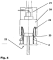
- the 3 to 5 show on the basis of schematic diagrams of the inventive method for producing a provided with an inner clamping ring air spring bellows for an air spring device.
- the method consists, as will be explained in more detail below, in that the air spring bellows is provided with the aid of a special handling method with the inner clamping ring.
- Fig. 3 shows the air spring bellows 4, as it is applied to a substantially cylindrical Blähbalg fitting 20 and the latter wrapped at its lower end.
- the air spring bellows 4 is connected airtight and thereby at its lower end to the lower of the Blähbalg 20 associated end pieces 21 and 22.
- the lower end piece 22 surrounds the bellows, so Blähbalg 20 and launched air spring bellows 4 pot-shaped with an envelope collar 23rd
- At least one of the end pieces 21, 22 of the inflation bellows is movable relative to the other end piece, whereby the Blähbalgin or the distance between the end pieces 21 and 22 during the Umtschreaes / Umbuckvons can be shortened.
- Fig. 4 now shows how the Blähbalg 20 is set to expand the adjacent air spring bellows 4 under internal pressure and the end pieces with inflated Blähbalg or air spring bellows are already moved together with shortening the distance between the end pieces 21 and 22.
- the lower end of the bellows 20 and Heilfederbalges 4 in the form an envelope 24 is transversely / transposed over the cup-shaped collar 23 formed as cup-shaped end.
- the folded portion of the air spring bellows 4 is set under pressure with the aid of running inside the Umtschkragens and exiting the envelope air channels, the envelope 24 of the bellows 4 folds back and returned to its initial state / mounting state air spring bellows 4 the inner clamping ring to form a radial fixed outwardly facing circumferential bulge 19, as in Fig. 2 shown.
- the air spring bellows is then removed from the inflatable bladder / from the end pieces and then installed with the outer guide 5 in the air spring device 1.
Landscapes
- Engineering & Computer Science (AREA)
- General Engineering & Computer Science (AREA)
- Mechanical Engineering (AREA)
- Fluid-Damping Devices (AREA)
- Diaphragms And Bellows (AREA)
Claims (3)
- Procédé de fabrication d'un soufflet (4) d'amortisseur pneumatique doté d'un anneau de serrage intérieur pour un dispositif (1) d'amortisseur pneumatique doté d'un soufflet (4) d'amortisseur pneumatique en matériau élastomère, d'un couvercle (2) d'amortisseur pneumatique et d'un piston (3) d'amortisseur pneumatique,
le soufflet (4) d'amortisseur pneumatique essentiellement libre en position d'utilisation étant fixé de manière étanche à l'air par sa première extrémité au piston (3) d'amortisseur pneumatique en formant un premier pli de déroulement (13) et par sa deuxième extrémité au couvercle (2) d'amortisseur pneumatique en formant un deuxième pli de déroulement (14) pour former avec le couvercle (2) d'amortisseur pneumatique et le piston (3) d'amortisseur pneumatique une chambre creuse (12) de volume élastique,
le dispositif (1) d'amortisseur pneumatique présentant un guide extérieur (5) en forme de manchon qui entoure tangentiellement le soufflet (4) d'amortisseur pneumatique et au moins un anneau (16) de serrage intérieur disposé à l'intérieur du soufflet (4) de ressort pneumatique,
le guide extérieur (5) étant fixé en correspondance mécanique et/ou en correspondance géométrique à l'aide de l'anneau (16) de serrage intérieur sur la surface extérieure du soufflet (4) d'amortisseur pneumatique,
le diamètre extérieur (17) de l'anneau (16) de serrage intérieur étant supérieur au diamètre extérieur (18) du soufflet (4) d'amortisseur pneumatique en conditions de délestage de pression et
l'anneau de serrage intérieur formant dans le soufflet d'amortisseur pneumatique non sous pression un bombage périphérique (19) qui est orienté radialement vers l'extérieur et qui correspond essentiellement au diamètre intérieur du guide extérieur (5),
caractérisé en ce que
le soufflet (4) d'amortisseur pneumatique est doté de l'anneau (16) de serrage intérieur par une opération de rabattement,a) en ce que le soufflet (4) d'amortisseur pneumatique appliqué sur un soufflet gonflable (20) essentiellement cylindrique et entourant ce dernier au moins en partie est raccordé de manière étanche à l'air par au moins l'une de ses extrémités à des pièces d'extrémité (21, 22) qui font partie du soufflet gonflable, au moins l'une des pièces d'extrémité étant configurée en forme de chapeau qui entoure le soufflet gonflable et au moins l'une des pièces d'extrémité du soufflet gonflable pouvant être déplacée par rapport à l'autre pièce d'extrémité de manière à raccourcir la longueur du soufflet gonflable,b) en ce que le soufflet gonflable est placé sous pression intérieure pour agrandir le soufflet d'amortisseur pneumatique qui y est appliqué,c) en ce que lorsque le soufflet gonflable ou le soufflet (4) d'amortisseur pneumatique sont gonflés, les pièces d'extrémité sont rapprochées dans le sens d'un raccourcissement de la longueur efficace du soufflet gonflable ou d'un raccourcissement de la distance entre les pièces d'extrémité (21, 22), de telle sorte qu'une extrémité du soufflet gonflable ou du soufflet (4) d'amortisseur pneumatique soit rabattue au-dessus de l'extrémité en forme de chapeau sous la forme d'un repli rabattu (24),d) en ce que la pression qui règne dans le soufflet gonflable (20) est partiellement délestée en inversant partiellement le raccourcissement, l'agrandissement et le rabattement du soufflet gonflable étant ainsi reculés tout en conservant le rabattement du soufflet (4) d'amortisseur pneumatique,e) en ce que l'anneau (16) de serrage intérieur est placé au-dessus du soufflet gonflable et sur l'emplacement de serrage (25) prévu à l'intérieur du soufflet (4) d'amortisseur pneumatique,f) en ce que la pression qui règne dans le soufflet gonflable est complètement délestée et les pièces d'extrémité (21, 22) sont écartées l'une de l'autre en inversant complètement le raccourcissement,g) en ce que la partie rabattue du soufflet (4) d'amortisseur pneumatique est placée sous pression d'air, le rabattement (24) du soufflet (4) d'amortisseur pneumatique étant également rabattu et le soufflet (4) d'amortisseur pneumatique ramené dans sa position initiale ou position de fabrication fixe l'anneau (16) de serrage intérieur en formant un bombage périphérique (19) orienté radialement vers l'extérieur, suite à quoih) le soufflet d'amortisseur pneumatique est enlevé du soufflet gonflable et/ou des pièces d'extrémité. - Procédé selon la revendication 1, caractérisé en ce que le soufflet gonflable entoure un mandrin de fabrication de longueur variable.
- Procédé selon les revendications 1 ou 2, caractérisé en ce que le soufflet gonflable peut être utilisé comme guide de montage de l'anneau intérieur de serrage dans un état de gonflement prédéterminé.
Applications Claiming Priority (2)
| Application Number | Priority Date | Filing Date | Title |
|---|---|---|---|
| DE102006052314.8A DE102006052314B4 (de) | 2006-11-07 | 2006-11-07 | Luftfedereinrichtung |
| PCT/EP2007/060038 WO2008055744A1 (fr) | 2006-11-07 | 2007-09-21 | Dispositif de suspension pneumatique |
Publications (3)
| Publication Number | Publication Date |
|---|---|
| EP2089637A1 EP2089637A1 (fr) | 2009-08-19 |
| EP2089637B1 EP2089637B1 (fr) | 2011-07-13 |
| EP2089637B2 true EP2089637B2 (fr) | 2016-06-15 |
Family
ID=38941866
Family Applications (1)
| Application Number | Title | Priority Date | Filing Date |
|---|---|---|---|
| EP07820460.9A Active EP2089637B2 (fr) | 2006-11-07 | 2007-09-21 | Dispositif de suspension pneumatique |
Country Status (7)
| Country | Link |
|---|---|
| US (1) | US8272627B2 (fr) |
| EP (1) | EP2089637B2 (fr) |
| JP (1) | JP5138696B2 (fr) |
| KR (1) | KR101426381B1 (fr) |
| AT (1) | ATE516453T1 (fr) |
| DE (1) | DE102006052314B4 (fr) |
| WO (1) | WO2008055744A1 (fr) |
Cited By (1)
| Publication number | Priority date | Publication date | Assignee | Title |
|---|---|---|---|---|
| CN111438507A (zh) * | 2020-04-14 | 2020-07-24 | 中车青岛四方车辆研究所有限公司 | 扣环胶囊的自动上下料装置、自动组装系统及方法 |
Families Citing this family (18)
| Publication number | Priority date | Publication date | Assignee | Title |
|---|---|---|---|---|
| DE102009003829B4 (de) * | 2009-04-27 | 2020-08-06 | Continental Teves Ag & Co. Ohg | Luftfedereinrichtung |
| DE102009025847A1 (de) * | 2009-05-20 | 2010-11-25 | Continental Aktiengesellschaft | Luftfedereinheit mit Lagerrollbag |
| DE102009025957A1 (de) | 2009-06-10 | 2010-12-16 | Continental Aktiengesellschaft | Schlauchrollbalg für eine Luftfeder |
| WO2012100098A1 (fr) * | 2011-01-19 | 2012-07-26 | Firestone Industrial Products Company, Llc | Ensemble piston à ressort à gaz ainsi qu'ensemble ressort à gaz et système de suspension comprenant celui-ci |
| DE102012201104B4 (de) * | 2011-04-06 | 2024-05-23 | Continental Automotive Technologies GmbH | Luftfeder mit Hybridbalg |
| US20140352528A1 (en) * | 2011-06-10 | 2014-12-04 | Maxine C. McKenzie | Air spring with constrained elastic sleeve |
| US10578180B2 (en) * | 2011-06-10 | 2020-03-03 | Richard Conaway | Air spring with constrained elastic sleeve |
| EP2780607B1 (fr) | 2011-11-15 | 2019-06-26 | Continental Teves AG & Co. OHG | Ressort pneumatique |
| DE102012103358A1 (de) * | 2012-04-18 | 2013-10-24 | Contitech Luftfedersysteme Gmbh | Abrollkolben für einen Luftfederrollbalg |
| US9636962B2 (en) | 2014-09-17 | 2017-05-02 | Continental Automotive Systems, Inc. | Bonded guide tube and bellow assembly for air spring |
| DE102015119579B4 (de) * | 2015-11-12 | 2021-08-12 | Dunlop Systems And Components | Luftfedereinheit |
| DE102016202642A1 (de) | 2016-01-29 | 2017-08-03 | Continental Teves Ag & Co. Ohg | Luftfeder mit Faltenbalg |
| US11040389B2 (en) * | 2018-12-06 | 2021-06-22 | Continental Automotive Systems, Inc. | Guide tube retainment feature during crimping of guide tubes |
| DE102020203165A1 (de) | 2020-02-13 | 2021-08-19 | Continental Teves Ag & Co. Ohg | Luftfeder mit einer Außenführung und ein Verfahren zur Herstellung einer Luftfeder |
| DE102020204753A1 (de) | 2020-03-12 | 2021-09-16 | Continental Teves Ag & Co. Ohg | Luftfeder mit einer Außenführung und ein Verfahren zur Herstellung einer Luftfeder |
| CN113431859A (zh) * | 2021-06-15 | 2021-09-24 | 上海保隆汽车科技(安徽)有限公司 | 空气弹簧及其装配装置、装配方法 |
| CN115383439B (zh) * | 2022-08-30 | 2024-03-12 | 株洲时代新材料科技股份有限公司 | 小曲囊式空气弹簧的气囊、盖板压装方法及装置 |
| DE102024208384B3 (de) * | 2024-09-04 | 2025-08-07 | Continental Automotive Technologies GmbH | Verfahren zum Aufweiten und Anlegen eines Rollbalgs an ein Anschlussteil einer Luftfeder und Vorrichtung zum Durchführen solch eines Verfahrens |
Family Cites Families (14)
| Publication number | Priority date | Publication date | Assignee | Title |
|---|---|---|---|---|
| GB1143665A (fr) * | 1965-12-04 | |||
| US4673168A (en) * | 1985-06-25 | 1987-06-16 | The Goodyear Tire & Rubber Company | Airspring and a method for making airspring flexible members |
| JPH0520956Y2 (fr) * | 1988-03-03 | 1993-05-28 | ||
| US4988082A (en) * | 1989-07-18 | 1991-01-29 | General Motors Corporation | Spliced air sleeve assembly for air spring damper |
| JPH07190118A (ja) * | 1993-12-27 | 1995-07-28 | Toyota Motor Corp | 空気ばね |
| DE59708336D1 (de) | 1996-12-17 | 2002-10-31 | Phoenix Ag | Luftfedersystem |
| DE29823508U1 (de) | 1998-05-07 | 1999-08-12 | Phoenix Ag, 21079 Hamburg | Luftfeder |
| DE10106065A1 (de) | 2000-03-02 | 2001-09-06 | Phoenix Ag | Luftfederanordnung |
| AU2001286821A1 (en) * | 2000-11-15 | 2002-05-27 | Bfs Diversified Products, Llc | Air spring for vibration isolation |
| DE10163819A1 (de) * | 2001-12-22 | 2003-07-03 | Contitech Luftfedersyst Gmbh | Doppelrollbalg-Federungseinrichtung |
| DE10163829A1 (de) * | 2001-12-22 | 2003-07-03 | Contitech Luftfedersyst Gmbh | Federungseinrichtung mit Doppelrollbalg |
| US6637733B1 (en) * | 2002-06-12 | 2003-10-28 | Bfs Diversified Products, Llc | Air spring with vibration isolation |
| JP2005147294A (ja) * | 2003-11-17 | 2005-06-09 | Mikimoto Co Ltd | 固定バンド及びその固定治具 |
| DE102004059764C5 (de) * | 2004-12-11 | 2013-06-06 | Continental Teves Ag & Co. Ohg | Luftfeder- und Dämpfereinheit |
-
2006
- 2006-11-07 DE DE102006052314.8A patent/DE102006052314B4/de active Active
-
2007
- 2007-09-21 EP EP07820460.9A patent/EP2089637B2/fr active Active
- 2007-09-21 JP JP2009535045A patent/JP5138696B2/ja not_active Expired - Fee Related
- 2007-09-21 KR KR1020097011773A patent/KR101426381B1/ko not_active Expired - Fee Related
- 2007-09-21 AT AT07820460T patent/ATE516453T1/de active
- 2007-09-21 WO PCT/EP2007/060038 patent/WO2008055744A1/fr not_active Ceased
- 2007-09-21 US US12/513,919 patent/US8272627B2/en active Active
Cited By (2)
| Publication number | Priority date | Publication date | Assignee | Title |
|---|---|---|---|---|
| CN111438507A (zh) * | 2020-04-14 | 2020-07-24 | 中车青岛四方车辆研究所有限公司 | 扣环胶囊的自动上下料装置、自动组装系统及方法 |
| CN111438507B (zh) * | 2020-04-14 | 2021-07-20 | 中车青岛四方车辆研究所有限公司 | 扣环胶囊的自动上下料装置、自动组装系统及方法 |
Also Published As
| Publication number | Publication date |
|---|---|
| KR20090083921A (ko) | 2009-08-04 |
| JP2010508482A (ja) | 2010-03-18 |
| US8272627B2 (en) | 2012-09-25 |
| US20100001446A1 (en) | 2010-01-07 |
| WO2008055744A1 (fr) | 2008-05-15 |
| ATE516453T1 (de) | 2011-07-15 |
| DE102006052314A1 (de) | 2008-05-08 |
| EP2089637B1 (fr) | 2011-07-13 |
| DE102006052314B4 (de) | 2024-09-12 |
| EP2089637A1 (fr) | 2009-08-19 |
| KR101426381B1 (ko) | 2014-08-05 |
| JP5138696B2 (ja) | 2013-02-06 |
Similar Documents
| Publication | Publication Date | Title |
|---|---|---|
| EP2089637B1 (fr) | Dispositif de suspension pneumatique | |
| EP2049815B1 (fr) | Ressort à air pour vehicules | |
| EP2984364B1 (fr) | Ressort pneumatique notamment pour vehicules | |
| EP2090801B1 (fr) | Soufflet roulant d'un ressort pneumatique | |
| DE112014002607T5 (de) | Endelement-Baugruppen und Federwegbegrenzte Baugruppen sowie diese umfassende Gasfeder-Baugruppen | |
| EP1031756B1 (fr) | Fixation d'un soufflet roulant d'un ressort pneumatique sur un élément de support | |
| EP0151696A1 (fr) | Suspension pneumatique, notamment pour véhicule de route | |
| EP2847487B1 (fr) | Ressort pneumatique et procédé pour le rabattement d'un soufflet amortisseur pneumatique d'un ressort pneumatique | |
| EP2003363A2 (fr) | Dispositif à ressort à air | |
| EP1321694A2 (fr) | Ressort à soufflet roulant tubulaire | |
| EP1984647B1 (fr) | Amortisseur pneumatique à guide externe | |
| DE102010000167B4 (de) | Luftfeder für ein Kraftfahrzeug | |
| DE102009025957A1 (de) | Schlauchrollbalg für eine Luftfeder | |
| EP1657467B1 (fr) | Procédé d'assemblage d'un ressort pneumatique | |
| DE102004015602B4 (de) | Luftfedereinrichtung | |
| DE102005041800B3 (de) | Luftfederbalg | |
| EP1736683B1 (fr) | Amortisseurs pneumatiques a soufflet tubulaire | |
| DE102020203165A1 (de) | Luftfeder mit einer Außenführung und ein Verfahren zur Herstellung einer Luftfeder | |
| EP1548320A1 (fr) | Ressort pneumatique | |
| WO2014111183A1 (fr) | Ressort pneumatique | |
| DE102011119206B4 (de) | Gasfeder für eine Radaufhängung einesKraftfahrzeugs | |
| DE10031370A1 (de) | Crashenergieabsorbierende Anordnung | |
| DE202016102654U1 (de) | Luftfedereinheit für ein Kraftfahrzeug | |
| DE102016207873A1 (de) | Luftfedereinheit für ein Kraftfahrzeug | |
| EP2030770B1 (fr) | Procédé et dispositif destinés à replier une ébauche non vulcanisée |
Legal Events
| Date | Code | Title | Description |
|---|---|---|---|
| PUAI | Public reference made under article 153(3) epc to a published international application that has entered the european phase |
Free format text: ORIGINAL CODE: 0009012 |
|
| 17P | Request for examination filed |
Effective date: 20090608 |
|
| AK | Designated contracting states |
Kind code of ref document: A1 Designated state(s): AT BE BG CH CY CZ DE DK EE ES FI FR GB GR HU IE IS IT LI LT LU LV MC MT NL PL PT RO SE SI SK TR |
|
| DAX | Request for extension of the european patent (deleted) | ||
| RAP1 | Party data changed (applicant data changed or rights of an application transferred) |
Owner name: CONTINENTAL TEVES AG & CO. OHG |
|
| GRAP | Despatch of communication of intention to grant a patent |
Free format text: ORIGINAL CODE: EPIDOSNIGR1 |
|
| GRAS | Grant fee paid |
Free format text: ORIGINAL CODE: EPIDOSNIGR3 |
|
| GRAA | (expected) grant |
Free format text: ORIGINAL CODE: 0009210 |
|
| AK | Designated contracting states |
Kind code of ref document: B1 Designated state(s): AT BE BG CH CY CZ DE DK EE ES FI FR GB GR HU IE IS IT LI LT LU LV MC MT NL PL PT RO SE SI SK TR |
|
| REG | Reference to a national code |
Ref country code: GB Ref legal event code: FG4D Free format text: NOT ENGLISH |
|
| REG | Reference to a national code |
Ref country code: CH Ref legal event code: EP |
|
| REG | Reference to a national code |
Ref country code: IE Ref legal event code: FG4D Free format text: LANGUAGE OF EP DOCUMENT: GERMAN |
|
| REG | Reference to a national code |
Ref country code: DE Ref legal event code: R096 Ref document number: 502007007677 Country of ref document: DE Effective date: 20110908 |
|
| REG | Reference to a national code |
Ref country code: NL Ref legal event code: VDEP Effective date: 20110713 |
|
| PG25 | Lapsed in a contracting state [announced via postgrant information from national office to epo] |
Ref country code: LT Free format text: LAPSE BECAUSE OF FAILURE TO SUBMIT A TRANSLATION OF THE DESCRIPTION OR TO PAY THE FEE WITHIN THE PRESCRIBED TIME-LIMIT Effective date: 20110713 Ref country code: IS Free format text: LAPSE BECAUSE OF FAILURE TO SUBMIT A TRANSLATION OF THE DESCRIPTION OR TO PAY THE FEE WITHIN THE PRESCRIBED TIME-LIMIT Effective date: 20111113 Ref country code: FI Free format text: LAPSE BECAUSE OF FAILURE TO SUBMIT A TRANSLATION OF THE DESCRIPTION OR TO PAY THE FEE WITHIN THE PRESCRIBED TIME-LIMIT Effective date: 20110713 Ref country code: PT Free format text: LAPSE BECAUSE OF FAILURE TO SUBMIT A TRANSLATION OF THE DESCRIPTION OR TO PAY THE FEE WITHIN THE PRESCRIBED TIME-LIMIT Effective date: 20111114 Ref country code: SE Free format text: LAPSE BECAUSE OF FAILURE TO SUBMIT A TRANSLATION OF THE DESCRIPTION OR TO PAY THE FEE WITHIN THE PRESCRIBED TIME-LIMIT Effective date: 20110713 Ref country code: NL Free format text: LAPSE BECAUSE OF FAILURE TO SUBMIT A TRANSLATION OF THE DESCRIPTION OR TO PAY THE FEE WITHIN THE PRESCRIBED TIME-LIMIT Effective date: 20110713 |
|
| REG | Reference to a national code |
Ref country code: IE Ref legal event code: FD4D |
|
| PG25 | Lapsed in a contracting state [announced via postgrant information from national office to epo] |
Ref country code: PL Free format text: LAPSE BECAUSE OF FAILURE TO SUBMIT A TRANSLATION OF THE DESCRIPTION OR TO PAY THE FEE WITHIN THE PRESCRIBED TIME-LIMIT Effective date: 20110713 Ref country code: CY Free format text: LAPSE BECAUSE OF FAILURE TO SUBMIT A TRANSLATION OF THE DESCRIPTION OR TO PAY THE FEE WITHIN THE PRESCRIBED TIME-LIMIT Effective date: 20110713 Ref country code: GR Free format text: LAPSE BECAUSE OF FAILURE TO SUBMIT A TRANSLATION OF THE DESCRIPTION OR TO PAY THE FEE WITHIN THE PRESCRIBED TIME-LIMIT Effective date: 20111014 Ref country code: LV Free format text: LAPSE BECAUSE OF FAILURE TO SUBMIT A TRANSLATION OF THE DESCRIPTION OR TO PAY THE FEE WITHIN THE PRESCRIBED TIME-LIMIT Effective date: 20110713 Ref country code: SI Free format text: LAPSE BECAUSE OF FAILURE TO SUBMIT A TRANSLATION OF THE DESCRIPTION OR TO PAY THE FEE WITHIN THE PRESCRIBED TIME-LIMIT Effective date: 20110713 |
|
| BERE | Be: lapsed |
Owner name: CONTINENTAL TEVES A.G. & CO. OHG Effective date: 20110930 |
|
| PLBI | Opposition filed |
Free format text: ORIGINAL CODE: 0009260 |
|
| PG25 | Lapsed in a contracting state [announced via postgrant information from national office to epo] |
Ref country code: IE Free format text: LAPSE BECAUSE OF FAILURE TO SUBMIT A TRANSLATION OF THE DESCRIPTION OR TO PAY THE FEE WITHIN THE PRESCRIBED TIME-LIMIT Effective date: 20110713 Ref country code: MC Free format text: LAPSE BECAUSE OF NON-PAYMENT OF DUE FEES Effective date: 20110930 Ref country code: CZ Free format text: LAPSE BECAUSE OF FAILURE TO SUBMIT A TRANSLATION OF THE DESCRIPTION OR TO PAY THE FEE WITHIN THE PRESCRIBED TIME-LIMIT Effective date: 20110713 Ref country code: SK Free format text: LAPSE BECAUSE OF FAILURE TO SUBMIT A TRANSLATION OF THE DESCRIPTION OR TO PAY THE FEE WITHIN THE PRESCRIBED TIME-LIMIT Effective date: 20110713 |
|
| REG | Reference to a national code |
Ref country code: CH Ref legal event code: PL |
|
| 26 | Opposition filed |
Opponent name: CARL FREUDENBERG KG Effective date: 20120326 |
|
| PLAX | Notice of opposition and request to file observation + time limit sent |
Free format text: ORIGINAL CODE: EPIDOSNOBS2 |
|
| PG25 | Lapsed in a contracting state [announced via postgrant information from national office to epo] |
Ref country code: RO Free format text: LAPSE BECAUSE OF FAILURE TO SUBMIT A TRANSLATION OF THE DESCRIPTION OR TO PAY THE FEE WITHIN THE PRESCRIBED TIME-LIMIT Effective date: 20110713 Ref country code: EE Free format text: LAPSE BECAUSE OF FAILURE TO SUBMIT A TRANSLATION OF THE DESCRIPTION OR TO PAY THE FEE WITHIN THE PRESCRIBED TIME-LIMIT Effective date: 20110713 Ref country code: IT Free format text: LAPSE BECAUSE OF FAILURE TO SUBMIT A TRANSLATION OF THE DESCRIPTION OR TO PAY THE FEE WITHIN THE PRESCRIBED TIME-LIMIT Effective date: 20110713 |
|
| GBPC | Gb: european patent ceased through non-payment of renewal fee |
Effective date: 20111013 |
|
| REG | Reference to a national code |
Ref country code: DE Ref legal event code: R026 Ref document number: 502007007677 Country of ref document: DE Effective date: 20120326 |
|
| PG25 | Lapsed in a contracting state [announced via postgrant information from national office to epo] |
Ref country code: BE Free format text: LAPSE BECAUSE OF NON-PAYMENT OF DUE FEES Effective date: 20110930 Ref country code: DK Free format text: LAPSE BECAUSE OF FAILURE TO SUBMIT A TRANSLATION OF THE DESCRIPTION OR TO PAY THE FEE WITHIN THE PRESCRIBED TIME-LIMIT Effective date: 20110713 |
|
| PG25 | Lapsed in a contracting state [announced via postgrant information from national office to epo] |
Ref country code: CH Free format text: LAPSE BECAUSE OF NON-PAYMENT OF DUE FEES Effective date: 20110930 Ref country code: LI Free format text: LAPSE BECAUSE OF NON-PAYMENT OF DUE FEES Effective date: 20110930 |
|
| PG25 | Lapsed in a contracting state [announced via postgrant information from national office to epo] |
Ref country code: GB Free format text: LAPSE BECAUSE OF NON-PAYMENT OF DUE FEES Effective date: 20111013 |
|
| PLAF | Information modified related to communication of a notice of opposition and request to file observations + time limit |
Free format text: ORIGINAL CODE: EPIDOSCOBS2 |
|
| PLBB | Reply of patent proprietor to notice(s) of opposition received |
Free format text: ORIGINAL CODE: EPIDOSNOBS3 |
|
| PG25 | Lapsed in a contracting state [announced via postgrant information from national office to epo] |
Ref country code: MT Free format text: LAPSE BECAUSE OF FAILURE TO SUBMIT A TRANSLATION OF THE DESCRIPTION OR TO PAY THE FEE WITHIN THE PRESCRIBED TIME-LIMIT Effective date: 20110713 |
|
| PG25 | Lapsed in a contracting state [announced via postgrant information from national office to epo] |
Ref country code: ES Free format text: LAPSE BECAUSE OF FAILURE TO SUBMIT A TRANSLATION OF THE DESCRIPTION OR TO PAY THE FEE WITHIN THE PRESCRIBED TIME-LIMIT Effective date: 20111024 |
|
| PLCK | Communication despatched that opposition was rejected |
Free format text: ORIGINAL CODE: EPIDOSNREJ1 |
|
| PG25 | Lapsed in a contracting state [announced via postgrant information from national office to epo] |
Ref country code: LU Free format text: LAPSE BECAUSE OF NON-PAYMENT OF DUE FEES Effective date: 20110921 |
|
| PG25 | Lapsed in a contracting state [announced via postgrant information from national office to epo] |
Ref country code: BG Free format text: LAPSE BECAUSE OF FAILURE TO SUBMIT A TRANSLATION OF THE DESCRIPTION OR TO PAY THE FEE WITHIN THE PRESCRIBED TIME-LIMIT Effective date: 20111013 |
|
| APBM | Appeal reference recorded |
Free format text: ORIGINAL CODE: EPIDOSNREFNO |
|
| APBP | Date of receipt of notice of appeal recorded |
Free format text: ORIGINAL CODE: EPIDOSNNOA2O |
|
| APAH | Appeal reference modified |
Free format text: ORIGINAL CODE: EPIDOSCREFNO |
|
| PLAB | Opposition data, opponent's data or that of the opponent's representative modified |
Free format text: ORIGINAL CODE: 0009299OPPO |
|
| R26 | Opposition filed (corrected) |
Opponent name: CARL FREUDENBERG KG Effective date: 20120326 |
|
| PG25 | Lapsed in a contracting state [announced via postgrant information from national office to epo] |
Ref country code: TR Free format text: LAPSE BECAUSE OF FAILURE TO SUBMIT A TRANSLATION OF THE DESCRIPTION OR TO PAY THE FEE WITHIN THE PRESCRIBED TIME-LIMIT Effective date: 20110713 |
|
| PG25 | Lapsed in a contracting state [announced via postgrant information from national office to epo] |
Ref country code: HU Free format text: LAPSE BECAUSE OF FAILURE TO SUBMIT A TRANSLATION OF THE DESCRIPTION OR TO PAY THE FEE WITHIN THE PRESCRIBED TIME-LIMIT Effective date: 20110713 |
|
| REG | Reference to a national code |
Ref country code: AT Ref legal event code: MM01 Ref document number: 516453 Country of ref document: AT Kind code of ref document: T Effective date: 20120921 |
|
| PG25 | Lapsed in a contracting state [announced via postgrant information from national office to epo] |
Ref country code: AT Free format text: LAPSE BECAUSE OF NON-PAYMENT OF DUE FEES Effective date: 20120921 |
|
| REG | Reference to a national code |
Ref country code: FR Ref legal event code: PLFP Year of fee payment: 9 |
|
| APBQ | Date of receipt of statement of grounds of appeal recorded |
Free format text: ORIGINAL CODE: EPIDOSNNOA3O |
|
| APBU | Appeal procedure closed |
Free format text: ORIGINAL CODE: EPIDOSNNOA9O |
|
| PUAH | Patent maintained in amended form |
Free format text: ORIGINAL CODE: 0009272 |
|
| STAA | Information on the status of an ep patent application or granted ep patent |
Free format text: STATUS: PATENT MAINTAINED AS AMENDED |
|
| 27A | Patent maintained in amended form |
Effective date: 20160615 |
|
| AK | Designated contracting states |
Kind code of ref document: B2 Designated state(s): AT BE BG CH CY CZ DE DK EE ES FI FR GB GR HU IE IS IT LI LT LU LV MC MT NL PL PT RO SE SI SK TR |
|
| REG | Reference to a national code |
Ref country code: DE Ref legal event code: R102 Ref document number: 502007007677 Country of ref document: DE |
|
| REG | Reference to a national code |
Ref country code: FR Ref legal event code: PLFP Year of fee payment: 10 |
|
| REG | Reference to a national code |
Ref country code: FR Ref legal event code: PLFP Year of fee payment: 11 |
|
| REG | Reference to a national code |
Ref country code: FR Ref legal event code: PLFP Year of fee payment: 12 |
|
| PGFP | Annual fee paid to national office [announced via postgrant information from national office to epo] |
Ref country code: FR Payment date: 20190927 Year of fee payment: 13 |
|
| PG25 | Lapsed in a contracting state [announced via postgrant information from national office to epo] |
Ref country code: FR Free format text: LAPSE BECAUSE OF NON-PAYMENT OF DUE FEES Effective date: 20200930 |
|
| REG | Reference to a national code |
Ref country code: DE Ref legal event code: R081 Ref document number: 502007007677 Country of ref document: DE Owner name: CONTINENTAL AUTOMOTIVE TECHNOLOGIES GMBH, DE Free format text: FORMER OWNER: CONTINENTAL TEVES AG & CO. OHG, 60488 FRANKFURT, DE Ref country code: DE Ref legal event code: R081 Ref document number: 502007007677 Country of ref document: DE Owner name: AUMOVIO GERMANY GMBH, DE Free format text: FORMER OWNER: CONTINENTAL TEVES AG & CO. OHG, 60488 FRANKFURT, DE |
|
| P01 | Opt-out of the competence of the unified patent court (upc) registered |
Effective date: 20230522 |
|
| REG | Reference to a national code |
Ref country code: DE Ref legal event code: R081 Ref document number: 502007007677 Country of ref document: DE Owner name: CONTINENTAL AUTOMOTIVE TECHNOLOGIES GMBH, DE Free format text: FORMER OWNER: CONTINENTAL AUTOMOTIVE TECHNOLOGIES GMBH, 30165 HANNOVER, DE Ref country code: DE Ref legal event code: R081 Ref document number: 502007007677 Country of ref document: DE Owner name: AUMOVIO GERMANY GMBH, DE Free format text: FORMER OWNER: CONTINENTAL AUTOMOTIVE TECHNOLOGIES GMBH, 30165 HANNOVER, DE |
|
| PGFP | Annual fee paid to national office [announced via postgrant information from national office to epo] |
Ref country code: DE Payment date: 20240930 Year of fee payment: 18 |
|
| REG | Reference to a national code |
Ref country code: DE Ref legal event code: R081 Ref document number: 502007007677 Country of ref document: DE Owner name: AUMOVIO GERMANY GMBH, DE Free format text: FORMER OWNER: CONTINENTAL AUTOMOTIVE TECHNOLOGIES GMBH, 30175 HANNOVER, DE |