EP2089726B1 - Compteur électrique équipé d'une alimentation à mode de commutation - Google Patents
Compteur électrique équipé d'une alimentation à mode de commutation Download PDFInfo
- Publication number
- EP2089726B1 EP2089726B1 EP07817946.2A EP07817946A EP2089726B1 EP 2089726 B1 EP2089726 B1 EP 2089726B1 EP 07817946 A EP07817946 A EP 07817946A EP 2089726 B1 EP2089726 B1 EP 2089726B1
- Authority
- EP
- European Patent Office
- Prior art keywords
- transformer
- electricity meter
- electricity
- measuring
- voltage
- Prior art date
- Legal status (The legal status is an assumption and is not a legal conclusion. Google has not performed a legal analysis and makes no representation as to the accuracy of the status listed.)
- Active
Links
Images
Classifications
-
- G—PHYSICS
- G01—MEASURING; TESTING
- G01R—MEASURING ELECTRIC VARIABLES; MEASURING MAGNETIC VARIABLES
- G01R22/00—Arrangements for measuring time integral of electric power or current, e.g. electricity meters
- G01R22/06—Arrangements for measuring time integral of electric power or current, e.g. electricity meters by electronic methods
-
- G—PHYSICS
- G01—MEASURING; TESTING
- G01R—MEASURING ELECTRIC VARIABLES; MEASURING MAGNETIC VARIABLES
- G01R21/00—Arrangements for measuring electric power or power factor
- G01R21/133—Arrangements for measuring electric power or power factor by using digital technique
Definitions
- the invention relates to an electricity meter, particularly an electricity meter for measuring electricity consumption in polyphasic electricity systems, including high-precision meters for measuring electricity consumption of a user in an electricity supply network in connection with payment to the electricity provider for consumed electric energy.
- Meters of prior art for measuring electric energy such as that disclosed in DE 29 23 341 A1 contain a measuring circuit, one for each phase, determining the electric power based on a detection of a voltage and a current, the current being detected as a voltage across a known shunt resistor.
- These measuring circuits are often integrated measuring circuits being supplied with low voltage and processing low voltage signals. Current is measured as the voltage over a shunt resistor in relation to the voltage on a phase.
- the measuring circuit may be placed directly on the phase potential or on a different potential, and the measure voltage must therefore be transferred through a galvanic separation.
- the phase potentials In polyphasic electricity meters the phase potentials must be kept separate, and it is therefore necessary to galvanically separate the measurements or the supply to the measuring circuits.
- such polyphasic meters include a transformer transforming the supply voltage (often 50 Hz) down to a voltage level suitable for supplying a measuring circuit for each phase, a meter unit calculating the total electricity consumption, and for example a radio module for remote reading and possibly modules with additional functions attached to the electricity meter.
- common iron core transformers are used to supply low voltage to the measuring circuits. This may be low voltage for the supply of the measuring circuits, but the transformer may also be used to transfer measuring voltage between galvanically separated potentials.
- transformers having high induction are used so as not to impose load, and at the same time the transformer must have a good coupling to ensure a stable ratio between input and output voltage.
- the induction is proportional to the permeability of the iron, and if the iron is saturated, permeability is considerably reduced.
- the transformer is to transform the quite low frequency 50 Hz of the supply voltage, it is vulnerable to external magnetic influence, which will change the permeability and thereby damage the intended properties of the transformer.
- an electricity meter for measuring electricity consumption in an electricity supply network with one or more phases, wherein the electricity meter comprises
- the transformer can suitably feed the measuring circuits even if the properties of the transformer core are influenced significantly by a strong magnet.
- the transformer is supplied with voltage from switch mode voltage supply which preferably operates with a switch frequency that is significantly higher than the 50 Hz of the electricity supply network, e.g. 10 kHz or 100 kHz or possibly higher.
- the transformer may have a ferrite core or may not have a core at all.
- the switch mode circuit is furthermore provided with feedback on the voltage on a secondary winding on the transformer, such that the switch mode circuit is able to regulate the energy supply to the primary winding on the transformer in order to maintain a constant voltage on the secondary winding.
- Such feedback from the secondary side of the transformer will have the effect that changes in the transformer, at least within certain limits, will not influence the output voltage.
- the transformer is used solely as voltage supply to the measuring circuits for each phase, but not as a transformer for measuring voltage for each phase. This has the effect that the measuring result can only be externally influenced if the properties of the transformer are changed to such a degree that the voltage supply cannot supply sufficient voltage for the measuring circuits to be able to work. The probability of this happening is considerably reduced with the use of the switch mode voltage supply combined with a low induction transformer and for example feedback as mentioned above.
- the measuring circuits can use the shunt resistor principle for measuring current consumption.
- the transformer further comprises at least one separate galvanically separated secondary winding for the voltage supply to additional circuits in relation to the electricity meter, e.g. a calculation circuit for receiving energy consumption data from each of the separate measuring circuits and calculation of a total energy consumption as a sum thereof.
- Additional circuits may also comprise a radio module for wireless communication of electricity consumption data, various circuits for user interface such as display etc. Calculating circuits and additional circuits may preferably be supplied by one common secondary winding.
- the electricity meter has two measuring circuits on each of two phases, or three measuring circuits on each of three phases.
- the voltage supply is connected to all phases such that the voltage supply, including the switch mode circuit, is supplied with voltage when there is voltage on just one of the phases. This ensures that the calculating circuit is supplied with voltage when there is voltage on just one of the phases.
- the electricity meter according to the invention is suitable for all types of high precision measuring of electricity consumption, i.e. for use at private consumers or companies which are supplied with electricity from one electricity provider via an electricity supply network.
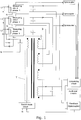
- figure 1 shows a survey diagram of a three phase electricity meter according to the invention.
- Figure 1 shows an electricity meter for measuring the total electricity consumption on the three phases L1, L2 and L3.
- N denotes "neutral”.
- Separate measuring circuits for each of the phases L1, L2, L3 measure and calculate an energy consumption for each phase and communicate this result, via an optocoupler, to a calculation circuit which sums up the consumption results for each of the phases L1, L2, L3 and thus calculates a total energy consumption.
- the additional circuits may be a communication module, e.g. a radio module coupled to the calculating circuit in such a way that the total energy, and any other data, may be sent wirelessly to corresponding meters coupled in a wireless network, or directly to a reading central.
- a communication module e.g. a radio module coupled to the calculating circuit in such a way that the total energy, and any other data, may be sent wirelessly to corresponding meters coupled in a wireless network, or directly to a reading central.
- the separate measuring circuits for each of the three phases L1, L2, L3 are directly coupled to the phases L1, L2, L3 in such a way that they are able to measure the voltage of each of the phases L1, L2, L3.
- the measuring circuits determine the current drawn on each of the phases based on the shunt resistor principle. They are therefore coupled directly to the voltage potential for each phase and must therefore be supplied with voltage separately with galvanic separation.
- the transformer T therefore has separate secondary windings which are galvanically separated from each other for voltage supply of each of the measuring circuits.
- Calculating circuits, additional circuits and feedback (optocoupler) for the switch mode circuit in the switch mode voltage supply are furthermore supplied with voltage from an additional secondary winding on the transformer T, as this secondary winding is galvanically separated from the secondary windings for the supply to the measuring circuits.
- the primary winding of the transformer T is charged with energy from a coupled switch mode circuit operating with a switch frequency of preferably 100 kHz or more.
- the switch mode circuit is connected to the primary winding of the transformer, and the primary winding is connected to the phases L1, L2, L3 via diodes in such a way that there will be supply voltage to switch mode circuits and calculating circuits when there is just voltage on one of the three phases L1, L2, L3.
- a feedback circuit is connected to the same secondary winding as the calculating circuit and any additional circuits.
- the feedback circuit is connected to the switch mode circuit and provides the switch mode circuit with information on the voltage level feeding the calculating circuit.
- the switch mode circuit then regulates its energy supply to the primary winding based on this information. It has been decided to let the switch mode circuit regulate the energy supply to the primary winding based on the secondary winding feeding the calculating circuit and any additional circuits, as these circuits have the highest consumption, whereas the measuring circuits have a low consumption.
- the switch mode circuit is preferably supplied with voltage by the primary winding via an integrated high voltage regulator, alternatively through an extra secondary winding on the transformer.
- the transformer T has a ferrite core combined with a large air gap such that its primary induction is maximally 20 times larger with the core being mounted than without the core being mounted, preferably the primary induction is 5-15 times larger with the core being mounted than without the core being mounted. Furthermore, it is preferred to dimension the voltage supply so as to supply sufficient power to the coupled circuits, i.e. measuring circuits, calculating circuits and any other circuits, without core in the transformer T. In combination with the described feedback coupling of the switch mode circuit, this means that the electricity meter can work almost without external influence by a strong magnetic field.
Landscapes
- Engineering & Computer Science (AREA)
- Power Engineering (AREA)
- Physics & Mathematics (AREA)
- General Physics & Mathematics (AREA)
- Measurement Of Current Or Voltage (AREA)
Claims (13)
- Compteur électrique permettant de mesurer la consommation d'énergie électrique dans un réseau d'alimentation électrique comprenant une ou plusieurs phases (L1,L2,L3), dans lequel le compteur électrique comprend :- un circuit de mesure pour chacune de la ou plusieurs phases pour la mesure de l'énergie électrique de chaque phase,- une tension d'alimentation étant fournie avec de l'électricité provenant d'un réseau d'alimentation électrique, la tension d'alimentation comprenantcaractérisé en ce que le transformateur est alimenté par la tension provenant du circuit à mode de commutation fonctionnant avec une fréquence de commutation sensiblement supérieure à celle du réseau d'alimentation électrique, de sorte que la tension d'alimentation puisse fournir une alimentation suffisante pour alimenter les circuits de mesure et de calcul sans noyau dans le transformateur.- un circuit à mode de commutation, et- un transformateur (T) dont l'enroulement principal est connecté à la sortie du circuit à mode de commutation, le transformateur comprenant des enroulements secondaires distincts séparés par galvanisation pour l'alimentation des circuits de mesure séparés respectifs pour chaque phase,
- Compteur électrique selon la revendication 1, le transformateur comprenant en outre au moins un enroulement secondaire distinct séparé par galvanisation pour l'alimentation électrique des circuits additionnels relativement au compteur d'électricité.
- Compteur électrique selon la revendication 2, les circuits additionnels comprenant un circuit de calcul pour recevoir des données de consommation d'énergie pour chacun des circuits de mesure distincts, et pour le calcul d'une consommation d'énergie totale en tant que somme de ces derniers.
- Compteur électrique selon la revendication 3, dans lequel le circuit à mode de commutation reçoit des informations en retour sur la tension de l'au moins un enroulement secondaire séparé pour l'alimentation électrique du circuit de calcul, et dans lequel le circuit à mode de commutation utilise ces informations en retour pour la régulation de la fourniture d'énergie à l'enroulement principal sur le transformateur.
- Compteur électrique selon les revendications 2 à 4, les circuits additionnels comprenant un module radio pour les communications sans fil des données sur la consommation d'électricité.
- Compteur électrique selon une quelconque des revendications précédentes, dans lequel les circuits de mesure pour chacune des deux ou plusieurs phases mesurent le courant consommé à l'aide d'une résistance en dérivation.
- Compteur électrique selon une quelconque des revendications précédentes, comprenant deux circuits de mesure pour mesurer l'énergie électrique pour chacune des deux phases, et dans lequel le transformateur comprend deux enroulements secondaires pour l'alimentation des deux circuits de mesure respectifs.
- Compteur électrique selon une quelconque des revendications 1 à 6, comprenant trois circuits de mesure pour mesurer l'énergie électrique pour chacune des trois phases, et dans lequel le transformateur comprend deux enroulements secondaires pour l'alimentation des trois circuits de mesure respectifs.
- Compteur électrique selon une quelconque des revendications précédentes, dans lequel le circuit à mode de commutation utilise une fréquence de commutation de 10 kHz ou davantage.
- Compteur électrique selon la revendication 9, dans lequel le circuit à mode de commutation utilise une fréquence de commutation de 100 kHz ou davantage.
- Compteur électrique selon une quelconque des revendications précédentes, dans lequel la tension d'alimentation est connectée à deux ou plusieurs phases de sorte que le circuit à mode de commutation soit alimenté par une tension tant qu'il y a une tension sur une des deux ou plusieurs phases.
- Compteur électrique selon une quelconque des revendications précédentes, dans lequel le transformateur possède un noyau et est conçu avec un entrefer dimensionné de sorte qu'une induction principale dans le transformateur avec le noyau monté est inférieure à 20 fois la taille de l'induction principale correspondante pour le transformateur sans le noyau étant monté.
- Compteur électrique selon la revendication 12, le noyau du transformateur étant un noyau de ferrite.
Applications Claiming Priority (2)
| Application Number | Priority Date | Filing Date | Title |
|---|---|---|---|
| DK200600285U DK200600285U3 (da) | 2006-11-07 | 2006-11-07 | EL-måler med switch mode spændingsforsyning |
| PCT/DK2007/050148 WO2008055507A1 (fr) | 2006-11-07 | 2007-10-11 | Compteur électrique équipé d'une alimentation à mode de commutation |
Publications (2)
| Publication Number | Publication Date |
|---|---|
| EP2089726A1 EP2089726A1 (fr) | 2009-08-19 |
| EP2089726B1 true EP2089726B1 (fr) | 2017-09-13 |
Family
ID=37450535
Family Applications (1)
| Application Number | Title | Priority Date | Filing Date |
|---|---|---|---|
| EP07817946.2A Active EP2089726B1 (fr) | 2006-11-07 | 2007-10-11 | Compteur électrique équipé d'une alimentation à mode de commutation |
Country Status (3)
| Country | Link |
|---|---|
| EP (1) | EP2089726B1 (fr) |
| DK (2) | DK200600285U3 (fr) |
| WO (1) | WO2008055507A1 (fr) |
Families Citing this family (8)
| Publication number | Priority date | Publication date | Assignee | Title |
|---|---|---|---|---|
| EP2154539B1 (fr) * | 2008-08-14 | 2011-04-13 | Kamstrup A/S | Compteur de consommation avec capteur magnétique |
| FI122736B (fi) * | 2009-01-26 | 2012-06-15 | Aidon Oy | Laite energiankulutuksen mittaamiseksi sekä elektroniikkakomponentti ja niiden käytöt |
| EP2251700A1 (fr) | 2009-05-12 | 2010-11-17 | Kamstrup A/S | Compteur de consommation magnétiquement immune |
| CN101860080B (zh) | 2010-05-18 | 2012-07-04 | 武汉国测科技股份有限公司 | 悬浮在高压侧的配网计量和保护一体化装置 |
| FR2999829B1 (fr) * | 2012-12-18 | 2014-11-28 | Sagemcom Energy & Telecom Sas | Equipement electrique adapte a etre connecte a un compteur d'energie electrique |
| FR3028619A1 (fr) * | 2014-11-18 | 2016-05-20 | Sagemcom Energy & Telecom Sas | Compteur d'energie electrique comprenant un shunt de mesure |
| CN105807130B (zh) * | 2014-12-29 | 2019-05-17 | 施耐德电气工业公司 | 一种多相电表及实现其的方法 |
| US11463002B2 (en) * | 2019-05-24 | 2022-10-04 | Texas Instruments Incorporated | Switch-mode power supply circuit |
Family Cites Families (4)
| Publication number | Priority date | Publication date | Assignee | Title |
|---|---|---|---|---|
| GB2042777B (en) * | 1979-02-21 | 1983-05-11 | South Eastern Elec Board | Electrical energy consumption meter |
| DE2923341C2 (de) * | 1979-06-08 | 1986-03-20 | Siemens AG, 1000 Berlin und 8000 München | Elektronische Mehrphasen-Elektrizitätszähler |
| GB2295682B (en) * | 1994-12-03 | 2000-01-19 | Siemens Measurements Ltd | Improvements in or relating to electricity meters |
| US7282944B2 (en) * | 2003-07-25 | 2007-10-16 | Power Measurement, Ltd. | Body capacitance electric field powered device for high voltage lines |
-
2006
- 2006-11-07 DK DK200600285U patent/DK200600285U3/da not_active IP Right Cessation
-
2007
- 2007-10-11 EP EP07817946.2A patent/EP2089726B1/fr active Active
- 2007-10-11 WO PCT/DK2007/050148 patent/WO2008055507A1/fr not_active Ceased
- 2007-10-11 DK DK07817946.2T patent/DK2089726T3/en active
Non-Patent Citations (1)
| Title |
|---|
| None * |
Also Published As
| Publication number | Publication date |
|---|---|
| DK200600285U1 (da) | 2006-11-24 |
| EP2089726A1 (fr) | 2009-08-19 |
| DK2089726T3 (en) | 2017-12-11 |
| DK200600285U3 (da) | 2006-12-08 |
| WO2008055507A1 (fr) | 2008-05-15 |
Similar Documents
| Publication | Publication Date | Title |
|---|---|---|
| EP2089726B1 (fr) | Compteur électrique équipé d'une alimentation à mode de commutation | |
| EP2241898B1 (fr) | Système de mesure de puissance électrique et système de commande de dispositif | |
| US7174261B2 (en) | Power line sensors and systems incorporating same | |
| EP2929359B1 (fr) | Capteur de mesure de tension isolé et à auto-étalonnage | |
| US6417661B1 (en) | Self powered current sensor | |
| US8102629B2 (en) | Leakage current compensation for high voltage transformers | |
| US20160209446A1 (en) | Current transformer system with characterization | |
| CN105637373B (zh) | 无线受电装置及其控制电路、使用了它的电子设备、接收功率的计算方法 | |
| WO2005005995A3 (fr) | Systeme et procede d'acquisition de tensions et mesure de tension dans un service electrique utilisant un transformateur de courant non actif | |
| US20210364558A1 (en) | Electronic electricity meter | |
| WO2016007651A1 (fr) | Survolteur pour compteur de service public | |
| GB2338790A (en) | Monitoring an AC load | |
| US20160003871A1 (en) | Contactless Device for Characterising An Electric Signal | |
| US6566895B2 (en) | Unbalanced three phase delta power measurement apparatus and method | |
| US20190265283A1 (en) | Measuring Transducer | |
| JP2010169565A (ja) | 電流計測装置およびそれを用いる電流計測システム | |
| WO2009091803A1 (fr) | Compensateur de tension pour des transformateurs de tension à double secondaire | |
| US20190020221A1 (en) | Inductive power transfer | |
| US20130151184A1 (en) | Meter Device | |
| KR100694818B1 (ko) | 주상변압기용 자체전원형 센서통신모듈 및 이를 이용한부하관리 시스템 | |
| WO2021003719A1 (fr) | Appareil de détection et procédé de détection | |
| GB2595719A (en) | Smart meter | |
| EP1426777A2 (fr) | Appareil de mesure de puissance électrique | |
| JP6249211B2 (ja) | 通信装置、及びそれを備えた配線遮断器、並びに分電盤 | |
| JPH02122609A (ja) | 誤差補償形変流器装置 |
Legal Events
| Date | Code | Title | Description |
|---|---|---|---|
| PUAI | Public reference made under article 153(3) epc to a published international application that has entered the european phase |
Free format text: ORIGINAL CODE: 0009012 |
|
| 17P | Request for examination filed |
Effective date: 20090331 |
|
| AK | Designated contracting states |
Kind code of ref document: A1 Designated state(s): AT BE BG CH CY CZ DE DK EE ES FI FR GB GR HU IE IS IT LI LT LU LV MC MT NL PL PT RO SE SI SK TR |
|
| AX | Request for extension of the european patent |
Extension state: AL BA HR MK RS |
|
| REG | Reference to a national code |
Ref country code: DE Ref legal event code: R079 Ref document number: 602007052379 Country of ref document: DE Free format text: PREVIOUS MAIN CLASS: G01R0021000000 Ipc: G01R0022060000 |
|
| GRAP | Despatch of communication of intention to grant a patent |
Free format text: ORIGINAL CODE: EPIDOSNIGR1 |
|
| RIC1 | Information provided on ipc code assigned before grant |
Ipc: G01R 21/133 20060101ALI20170302BHEP Ipc: G01R 22/06 20060101AFI20170302BHEP |
|
| INTG | Intention to grant announced |
Effective date: 20170324 |
|
| GRAS | Grant fee paid |
Free format text: ORIGINAL CODE: EPIDOSNIGR3 |
|
| GRAA | (expected) grant |
Free format text: ORIGINAL CODE: 0009210 |
|
| AK | Designated contracting states |
Kind code of ref document: B1 Designated state(s): AT BE BG CH CY CZ DE DK EE ES FI FR GB GR HU IE IS IT LI LT LU LV MC MT NL PL PT RO SE SI SK TR |
|
| AX | Request for extension of the european patent |
Extension state: AL BA HR MK RS |
|
| REG | Reference to a national code |
Ref country code: GB Ref legal event code: FG4D |
|
| REG | Reference to a national code |
Ref country code: CH Ref legal event code: EP |
|
| REG | Reference to a national code |
Ref country code: IE Ref legal event code: FG4D |
|
| REG | Reference to a national code |
Ref country code: AT Ref legal event code: REF Ref document number: 928683 Country of ref document: AT Kind code of ref document: T Effective date: 20171015 |
|
| REG | Reference to a national code |
Ref country code: DE Ref legal event code: R096 Ref document number: 602007052379 Country of ref document: DE |
|
| REG | Reference to a national code |
Ref country code: FR Ref legal event code: PLFP Year of fee payment: 11 |
|
| REG | Reference to a national code |
Ref country code: DK Ref legal event code: T3 Effective date: 20171207 |
|
| REG | Reference to a national code |
Ref country code: SE Ref legal event code: TRGR |
|
| REG | Reference to a national code |
Ref country code: NL Ref legal event code: MP Effective date: 20170913 |
|
| REG | Reference to a national code |
Ref country code: LT Ref legal event code: MG4D |
|
| PG25 | Lapsed in a contracting state [announced via postgrant information from national office to epo] |
Ref country code: LT Free format text: LAPSE BECAUSE OF FAILURE TO SUBMIT A TRANSLATION OF THE DESCRIPTION OR TO PAY THE FEE WITHIN THE PRESCRIBED TIME-LIMIT Effective date: 20170913 |
|
| REG | Reference to a national code |
Ref country code: AT Ref legal event code: MK05 Ref document number: 928683 Country of ref document: AT Kind code of ref document: T Effective date: 20170913 |
|
| PG25 | Lapsed in a contracting state [announced via postgrant information from national office to epo] |
Ref country code: GR Free format text: LAPSE BECAUSE OF FAILURE TO SUBMIT A TRANSLATION OF THE DESCRIPTION OR TO PAY THE FEE WITHIN THE PRESCRIBED TIME-LIMIT Effective date: 20171214 Ref country code: LV Free format text: LAPSE BECAUSE OF FAILURE TO SUBMIT A TRANSLATION OF THE DESCRIPTION OR TO PAY THE FEE WITHIN THE PRESCRIBED TIME-LIMIT Effective date: 20170913 Ref country code: BG Free format text: LAPSE BECAUSE OF FAILURE TO SUBMIT A TRANSLATION OF THE DESCRIPTION OR TO PAY THE FEE WITHIN THE PRESCRIBED TIME-LIMIT Effective date: 20171213 Ref country code: ES Free format text: LAPSE BECAUSE OF FAILURE TO SUBMIT A TRANSLATION OF THE DESCRIPTION OR TO PAY THE FEE WITHIN THE PRESCRIBED TIME-LIMIT Effective date: 20170913 |
|
| PG25 | Lapsed in a contracting state [announced via postgrant information from national office to epo] |
Ref country code: NL Free format text: LAPSE BECAUSE OF FAILURE TO SUBMIT A TRANSLATION OF THE DESCRIPTION OR TO PAY THE FEE WITHIN THE PRESCRIBED TIME-LIMIT Effective date: 20170913 |
|
| PG25 | Lapsed in a contracting state [announced via postgrant information from national office to epo] |
Ref country code: RO Free format text: LAPSE BECAUSE OF FAILURE TO SUBMIT A TRANSLATION OF THE DESCRIPTION OR TO PAY THE FEE WITHIN THE PRESCRIBED TIME-LIMIT Effective date: 20170913 Ref country code: PL Free format text: LAPSE BECAUSE OF FAILURE TO SUBMIT A TRANSLATION OF THE DESCRIPTION OR TO PAY THE FEE WITHIN THE PRESCRIBED TIME-LIMIT Effective date: 20170913 Ref country code: CZ Free format text: LAPSE BECAUSE OF FAILURE TO SUBMIT A TRANSLATION OF THE DESCRIPTION OR TO PAY THE FEE WITHIN THE PRESCRIBED TIME-LIMIT Effective date: 20170913 |
|
| PG25 | Lapsed in a contracting state [announced via postgrant information from national office to epo] |
Ref country code: EE Free format text: LAPSE BECAUSE OF FAILURE TO SUBMIT A TRANSLATION OF THE DESCRIPTION OR TO PAY THE FEE WITHIN THE PRESCRIBED TIME-LIMIT Effective date: 20170913 Ref country code: AT Free format text: LAPSE BECAUSE OF FAILURE TO SUBMIT A TRANSLATION OF THE DESCRIPTION OR TO PAY THE FEE WITHIN THE PRESCRIBED TIME-LIMIT Effective date: 20170913 Ref country code: IS Free format text: LAPSE BECAUSE OF FAILURE TO SUBMIT A TRANSLATION OF THE DESCRIPTION OR TO PAY THE FEE WITHIN THE PRESCRIBED TIME-LIMIT Effective date: 20180113 Ref country code: IT Free format text: LAPSE BECAUSE OF FAILURE TO SUBMIT A TRANSLATION OF THE DESCRIPTION OR TO PAY THE FEE WITHIN THE PRESCRIBED TIME-LIMIT Effective date: 20170913 Ref country code: SK Free format text: LAPSE BECAUSE OF FAILURE TO SUBMIT A TRANSLATION OF THE DESCRIPTION OR TO PAY THE FEE WITHIN THE PRESCRIBED TIME-LIMIT Effective date: 20170913 |
|
| REG | Reference to a national code |
Ref country code: DE Ref legal event code: R097 Ref document number: 602007052379 Country of ref document: DE |
|
| PG25 | Lapsed in a contracting state [announced via postgrant information from national office to epo] |
Ref country code: MC Free format text: LAPSE BECAUSE OF FAILURE TO SUBMIT A TRANSLATION OF THE DESCRIPTION OR TO PAY THE FEE WITHIN THE PRESCRIBED TIME-LIMIT Effective date: 20170913 |
|
| PLBE | No opposition filed within time limit |
Free format text: ORIGINAL CODE: 0009261 |
|
| STAA | Information on the status of an ep patent application or granted ep patent |
Free format text: STATUS: NO OPPOSITION FILED WITHIN TIME LIMIT |
|
| REG | Reference to a national code |
Ref country code: IE Ref legal event code: MM4A |
|
| PG25 | Lapsed in a contracting state [announced via postgrant information from national office to epo] |
Ref country code: LU Free format text: LAPSE BECAUSE OF NON-PAYMENT OF DUE FEES Effective date: 20171011 |
|
| 26N | No opposition filed |
Effective date: 20180614 |
|
| REG | Reference to a national code |
Ref country code: BE Ref legal event code: MM Effective date: 20171031 |
|
| GBPC | Gb: european patent ceased through non-payment of renewal fee |
Effective date: 20171213 |
|
| PG25 | Lapsed in a contracting state [announced via postgrant information from national office to epo] |
Ref country code: BE Free format text: LAPSE BECAUSE OF NON-PAYMENT OF DUE FEES Effective date: 20171031 |
|
| REG | Reference to a national code |
Ref country code: FR Ref legal event code: PLFP Year of fee payment: 12 |
|
| PG25 | Lapsed in a contracting state [announced via postgrant information from national office to epo] |
Ref country code: MT Free format text: LAPSE BECAUSE OF NON-PAYMENT OF DUE FEES Effective date: 20171011 |
|
| PG25 | Lapsed in a contracting state [announced via postgrant information from national office to epo] |
Ref country code: IE Free format text: LAPSE BECAUSE OF NON-PAYMENT OF DUE FEES Effective date: 20171011 |
|
| PG25 | Lapsed in a contracting state [announced via postgrant information from national office to epo] |
Ref country code: GB Free format text: LAPSE BECAUSE OF NON-PAYMENT OF DUE FEES Effective date: 20171213 Ref country code: SI Free format text: LAPSE BECAUSE OF FAILURE TO SUBMIT A TRANSLATION OF THE DESCRIPTION OR TO PAY THE FEE WITHIN THE PRESCRIBED TIME-LIMIT Effective date: 20170913 |
|
| PG25 | Lapsed in a contracting state [announced via postgrant information from national office to epo] |
Ref country code: HU Free format text: LAPSE BECAUSE OF FAILURE TO SUBMIT A TRANSLATION OF THE DESCRIPTION OR TO PAY THE FEE WITHIN THE PRESCRIBED TIME-LIMIT; INVALID AB INITIO Effective date: 20071011 |
|
| PG25 | Lapsed in a contracting state [announced via postgrant information from national office to epo] |
Ref country code: CY Free format text: LAPSE BECAUSE OF NON-PAYMENT OF DUE FEES Effective date: 20170913 |
|
| PG25 | Lapsed in a contracting state [announced via postgrant information from national office to epo] |
Ref country code: TR Free format text: LAPSE BECAUSE OF FAILURE TO SUBMIT A TRANSLATION OF THE DESCRIPTION OR TO PAY THE FEE WITHIN THE PRESCRIBED TIME-LIMIT Effective date: 20170913 |
|
| PG25 | Lapsed in a contracting state [announced via postgrant information from national office to epo] |
Ref country code: PT Free format text: LAPSE BECAUSE OF FAILURE TO SUBMIT A TRANSLATION OF THE DESCRIPTION OR TO PAY THE FEE WITHIN THE PRESCRIBED TIME-LIMIT Effective date: 20170913 |
|
| PGFP | Annual fee paid to national office [announced via postgrant information from national office to epo] |
Ref country code: FR Payment date: 20221028 Year of fee payment: 16 |
|
| PGFP | Annual fee paid to national office [announced via postgrant information from national office to epo] |
Ref country code: FI Payment date: 20221020 Year of fee payment: 16 |
|
| PGFP | Annual fee paid to national office [announced via postgrant information from national office to epo] |
Ref country code: CH Payment date: 20221026 Year of fee payment: 16 |
|
| REG | Reference to a national code |
Ref country code: DE Ref legal event code: R084 Ref document number: 602007052379 Country of ref document: DE |
|
| PGFP | Annual fee paid to national office [announced via postgrant information from national office to epo] |
Ref country code: SE Payment date: 20231019 Year of fee payment: 17 |
|
| REG | Reference to a national code |
Ref country code: CH Ref legal event code: PL |
|
| PG25 | Lapsed in a contracting state [announced via postgrant information from national office to epo] |
Ref country code: CH Free format text: LAPSE BECAUSE OF NON-PAYMENT OF DUE FEES Effective date: 20231031 |
|
| PG25 | Lapsed in a contracting state [announced via postgrant information from national office to epo] |
Ref country code: FR Free format text: LAPSE BECAUSE OF NON-PAYMENT OF DUE FEES Effective date: 20231031 Ref country code: FI Free format text: LAPSE BECAUSE OF NON-PAYMENT OF DUE FEES Effective date: 20231011 Ref country code: CH Free format text: LAPSE BECAUSE OF NON-PAYMENT OF DUE FEES Effective date: 20231031 |
|
| REG | Reference to a national code |
Ref country code: SE Ref legal event code: EUG |
|
| PG25 | Lapsed in a contracting state [announced via postgrant information from national office to epo] |
Ref country code: SE Free format text: LAPSE BECAUSE OF NON-PAYMENT OF DUE FEES Effective date: 20241012 |
|
| PGFP | Annual fee paid to national office [announced via postgrant information from national office to epo] |
Ref country code: DE Payment date: 20251021 Year of fee payment: 19 |
|
| PGFP | Annual fee paid to national office [announced via postgrant information from national office to epo] |
Ref country code: DK Payment date: 20251027 Year of fee payment: 19 |