EP2089738B1 - Procédé pour calculer une réponse impulsionnelle exacte d'un réflecteur acoustique plan à un décalage nul dû à une source acoustique ponctuelle - Google Patents
Procédé pour calculer une réponse impulsionnelle exacte d'un réflecteur acoustique plan à un décalage nul dû à une source acoustique ponctuelle Download PDFInfo
- Publication number
- EP2089738B1 EP2089738B1 EP07736532.8A EP07736532A EP2089738B1 EP 2089738 B1 EP2089738 B1 EP 2089738B1 EP 07736532 A EP07736532 A EP 07736532A EP 2089738 B1 EP2089738 B1 EP 2089738B1
- Authority
- EP
- European Patent Office
- Prior art keywords
- reflector
- source
- response
- reflection
- zero
- Prior art date
- Legal status (The legal status is an assumption and is not a legal conclusion. Google has not performed a legal analysis and makes no representation as to the accuracy of the status listed.)
- Not-in-force
Links
- 230000004044 response Effects 0.000 title claims description 161
- 238000000034 method Methods 0.000 title claims description 76
- 238000004422 calculation algorithm Methods 0.000 claims description 28
- 238000007598 dipping method Methods 0.000 claims description 28
- 230000005012 migration Effects 0.000 claims description 11
- 238000013508 migration Methods 0.000 claims description 11
- 230000008859 change Effects 0.000 claims description 10
- 230000006870 function Effects 0.000 description 50
- 238000002474 experimental method Methods 0.000 description 12
- 230000008569 process Effects 0.000 description 7
- 230000000694 effects Effects 0.000 description 6
- 230000008901 benefit Effects 0.000 description 3
- 238000009795 derivation Methods 0.000 description 3
- 238000011156 evaluation Methods 0.000 description 3
- 230000002093 peripheral effect Effects 0.000 description 3
- 230000007480 spreading Effects 0.000 description 3
- 238000012937 correction Methods 0.000 description 2
- 230000001419 dependent effect Effects 0.000 description 2
- 230000001902 propagating effect Effects 0.000 description 2
- 230000002441 reversible effect Effects 0.000 description 2
- 238000012360 testing method Methods 0.000 description 2
- 241001632004 Tetrahymena sp. SIN Species 0.000 description 1
- 230000015572 biosynthetic process Effects 0.000 description 1
- 238000004364 calculation method Methods 0.000 description 1
- 230000003111 delayed effect Effects 0.000 description 1
- 238000005553 drilling Methods 0.000 description 1
- 238000007519 figuring Methods 0.000 description 1
- 229930195733 hydrocarbon Natural products 0.000 description 1
- 150000002430 hydrocarbons Chemical class 0.000 description 1
- 230000004048 modification Effects 0.000 description 1
- 238000012986 modification Methods 0.000 description 1
- 230000035515 penetration Effects 0.000 description 1
- 238000012545 processing Methods 0.000 description 1
- 230000000750 progressive effect Effects 0.000 description 1
- 230000009467 reduction Effects 0.000 description 1
- 238000009877 rendering Methods 0.000 description 1
- 238000005070 sampling Methods 0.000 description 1
- 238000000926 separation method Methods 0.000 description 1
- 238000003786 synthesis reaction Methods 0.000 description 1
- 230000002123 temporal effect Effects 0.000 description 1
- 230000009466 transformation Effects 0.000 description 1
- 238000010200 validation analysis Methods 0.000 description 1
Images




Classifications
-
- G—PHYSICS
- G01—MEASURING; TESTING
- G01V—GEOPHYSICS; GRAVITATIONAL MEASUREMENTS; DETECTING MASSES OR OBJECTS; TAGS
- G01V1/00—Seismology; Seismic or acoustic prospecting or detecting
- G01V1/28—Processing seismic data, e.g. for interpretation or for event detection
- G01V1/30—Analysis
Definitions
- the present invention relates to a method for computing an exact impulse response of a plane acoustic reflector at zero offset due to a point acoustic source useful for seismological applications.
- a novel and an exact algebraic formula for the impulse response of a plane acoustic reflector at zero offset due to a point acoustic source underlies the method cited in the present invention.
- An observation at zero offset represents the case when the seismic source and the receiver are located either at the same point or arbitrarily close to each other.
- Reflection seismology is a widely employed tool for exploration of hydrocarbons.
- the seismic exploration industry is focused on a particular type of experiment or, more precisely, a particular type of ensemble of experiments.
- a source of seismic energy is set off at a shallow depth near the surface of the earth and the upward scattered signal from the subsurface is recorded at an array of receiver located on the surface, relatively near the source compared to the depth of penetration of the signal into the earth.
- the distance from the source to a receiver is called offset.
- the output of the receiver is recorded from the time the source was set off. That is, the data represents the amount of time needed for a wave to travel down to a reflector of interest and back to the recording surface.
- Seismic data is grouped into traces, lines and surveys.
- a trace is an output of a receiver and a line is a group of traces, while a survey is a collection of lines from a geographical location.
- the entire array, source and receivers, is moved and the experiment is repeated many times.
- the interval of separation between the successive experiments will be of the order of a few tens of meters, with the full set of experiments carried out along a line, which is a few kilometers to a few tens of kilometers in length, or even an areal array whose sides are of those dimensions.
- data for coincident source and receiver is synthesized from the small offset data of the ensemble of experiments. This is achieved by time-shifting the data of each small offset experiment to approximate the arrival time that would occur, if the experiment had been a backscatter experiment at the midpoint between the source and the receiver, simulating a zero-offset condition. There are a number of positive consequences of this synthesis.
- inversion is to replace the time-dependence of the input data with a depth-dependence. After inversion the position of a peak on a trace indicates at what depth there is a change in the wavespeed, while the amplitude of the peak relates to the magnitude of that change.
- the migration and inversion algorithms used in the seismic industry assume the earth to be an acoustic medium, as assumed in the present invention.
- the complete wave equation solution is equal to the asymptotic solution only for a spherical reflector and never for a plane reflector.
- the reflected wavefield for a plane reflector has a longer tail in time domain than the incident wave, a result inconsistent with the solution of Hilterman (1975), according to which the complete wave equation response has the same time span as the incident wave. Therefore, the solution of Hilterman (1975) for the zero-offset reflection response of a plane acoustic reflector is incorrect.
- the main object of the present invention is to provide a method according to claim 1 for computing an exact impulse response and reflection response of a plane acoustic reflector at zero offset due to a point acoustic source useful for seismological applications, which obviates the drawbacks as detailed above.
- Another object of the present invention is to provide a reference standard, against which the zero-offset reflection response of a plane acoustic reflector computed by a seismic numerical modeling algorithm can be checked, and in case of a satisfactory agreement the algorithm can be designated as validated.
- Still yet another object of the present invention is to provide a method for computing accurate synthetic zero-offset reflection response of a planar reflector using which seismic migration and inversion algorithms can be tested and validated.
- a further object of the present invention is to provide a method for validating interpretation of a reflector as a planar structure by comparing the observed reflection response of the reflector and the exact reflection response in accordance with the method cited in the main object.
- a still further object of the present invention is to provide a method for estimating the seismic source-time function when the zero-offset reflection response of a planar reflector is given.
- the present invention provides a method for computing an exact impulse response of a plane acoustic reflector at zero offset due to a point acoustic source, which comprises, a method for computing an exact impulse response of a plane acoustic reflector at zero offset due to a point acoustic source useful for seismological applications, a method for computing a reference standard for the zero-offset reflection response of a plane acoustic reflector against which the reflection response computed by a seismic numerical modeling algorithm can be checked; and in case of a satisfactory agreement the algorithm can be designated as validated, a method for assessing the efficacy of asymptotic method for obtaining a seismic-reflection modeling solution, a method for computing zero-offset reflection response of a circular reflector observed at its central axis and up to a limited span of time, a method for computing accurate synthetic zero-offset seismic section due to a planar reflector (dipping or horizontal) using which seismic migration and inversion algorithms can be tested and validated,
- the present invention provides a method for computing an exact impulse response of a plane acoustic reflector at zero offset due to a point acoustic source, which comprises, a method for computing an exact impulse response of a plane acoustic reflector at zero offset due to a point acoustic source useful for seismological applications, a method for computing a reference standard for the zero-offset reflection response of a plane acoustic reflector against which the reflection response computed by a seismic numerical modeling algorithm can be checked; and in case of a satisfactory agreement the algorithm can be designated as validated, a method for assessing the efficacy of asymptotic method for obtaining a seismic-reflection modeling solution, a method for computing zero-offset reflection response of a circular reflector observed at its central axis and up to a limited span of time, a method for computing accurate synthetic zero-offset seismic section due to a planar reflector (dipping or horizontal) using which seismic migration and inversion algorithms can be tested and validated,
- an exact algebraic formula is provided for the impulse response of a plane acoustic reflector at zero offset due to a point acoustic source.
- a method for computing a reference standard for the zero-offset reflection response of a plane acoustic reflector against which the reflection response computed by a seismic numerical modeling algorithm can be checked and in case of a satisfactory agreement the algorithm can be designated as validated.
- a method for assessing the efficacy of the asymptotic method for obtaining a seismic-reflection modeling solution.
- a method for computing zero-offset reflection response of a circular reflector observed at its central axis and up to a limited span of time.
- a method for computing accurate synthetic zero-offset seismic section due to a planar reflector (dipping or horizontal) using which seismic migration and inversion algorithms can be tested and validated.
- a method for validating an interpretation of a reflector as a planar structure.
- a method for estimating the seismic source-time function when the zero-offset reflection response of a planar reflector is given.
- the problem is modeled as though the medium extends to negative infinity in x 3 .
- the effect of this would be to rescale the incident wave to be defined later by a factor of 2 and to rescale the final answer by a factor of 4.
- u S ( ⁇ ) is the Fourier transform of u S ( t ).
- Equation (9) is the starting point of the derivation leading to the formula of the present invention, i.e., the exact impulse response of an infinite plane reflector due to a point source and measured at zero offset.
- the first step consists of reversing the earlier point of view and treating u S ( ⁇ ) as the unknown when ⁇ ( x 3 ) is given.
- Equation (15) implies i ⁇ 0 it 16 c ⁇ t ⁇ ⁇ H t ⁇ ⁇ ⁇ u S ⁇ ⁇ 2 .
- Equation (19) is not exact, as its derivation entailed the restriction of Born approximation.
- the R.H.S. of the last expression would yield an asymptotic expansion that is indeed the ray expansion containing rays of all orders (Blockin, 1984).
- the infinitesimal quantity dR would be the reflection coefficient common to the rays of all orders.
- the feature of commonness would be true even for a finite reflection coefficient R ; because for a point source, an acoustic reflector and a constant density, the reflection coefficients associated with rays of all orders, in the relevant ray expansion, are identical and equal the relevant plane wave reflection coefficient; which, in the present case, is the reflection coefficient for normal incidence, (Brauin, 1984; Cerveny, 2001).
- the second term involving the Heaviside function denotes reflections from the points that are away from that projection.
- the two-way traveltime from the source to that terminal point and back constitutes the upper limit on traveltime up to which the response of the interface can be computed exactly.
- the response in a strict sense, represents the zero-offset and time-limited reflection from a circular reflector whose center is the perpendicular projection of the source point on to the reflector. In a less restricted sense, though, the response can represent the zero-offset reflection from a dipping interface whose nearest terminal point is relatively far from the perpendicular projection of the source point on to the interface.
- the impulse response presented in equation (23) decays with time; has, in a strict sense, an infinite time span and possesses a nearly flat tail indicating dominance there of very low frequencies, usually absent in seismic data.
- the truncated response represents impulse response of a circular reflector whose radius depends on truncation time. Rejection of very low frequencies, as done in acquiring seismic data, also has the effect of discarding the tail and truncating the response.
- Such truncated impulse response represents, in a strict sense, response of a circular reflector (dipping or horizontal) of a limited extent; and that of a planar reflector of a larger extent (dipping or horizontal) in a less restricted yet accurate sense.
- equation (23) in its entirety represents the complete wave equation response of the reflector
- the first term denotes the ray theoretical solution, also called the asymptotic solution (Carcione et al., 2002). This term is often the most significant because of its dominant energy and occurrence as a concentrated burst in time.
- the second term corresponds to the later part of the response that is diffuse in time and by and large results from the contributions of relatively lower frequencies. The energy of the second term becomes less and less significant with increasing radius of curvature of the incident wavefront at the reflector. If for a certain radius of curvature the effect of the second term is negligible in the reflection response, then for a greater radius of curvature the second term would definitely be negligible.
- Equation (23) being an expression for the impulse response of the reflector, constitutes the first key result of the present invention the equation (25) constitutes the second key result. It is worthwhile to restate what each symbol represents in equation (25).
- t two-way traveltime from the source/receiver point to the reflector and back.
- r(t) zero-offset reflection response of a plane reflector due to a point source
- R ⁇ c 2 c + ⁇ c
- c the wavespeed of the first medium (i.e., the one above the reflector)
- c + ⁇ c is the wavespeed of the second medium (i.e., the one below the reflector)
- h perpendicular distance of the reflector from the source/receiver point
- the response represents reflection from a reflector (dipping or horizontal) of one of the following types:
- the response obtained can serve several goals. First it would provide a reference standard against which the reflection response computed by a seismic numerical modeling algorithm can be judged. When a reasonable agreement exists between the two results the algorithm could be designated as validated.
- An accurate synthetic seismic section can be computed for a dipping or horizontal reflector in the following manner. To compute the synthetic zero-offset seismic section over a dipping reflector one can conceive of many source/receiver points on the earth's surface. For each such point the respective h, the depth to the reflector, is noted. Other relevant parameters involving the reflector such as c, ⁇ c , s(t) are uniform. The equation (25) can then obtain r(t) for each source/receiver location.
- the ensemble of responses for various source/receiver locations would constitute the synthetic seismic section for a single reflector which is also dipping.
- the synthetic section can be the input data for a migration or inversion algorithm. If an algorithm can recover the dipping reflector model initially assumed, then that is treated as validated.
- the response computable according to equation (25) can validate an interpretation such as the following.
- Equation (23) through (25) together yield a method for estimating the seismic source-time function when the zero-offset reflection response of a planar reflector, i.e. r(t) is observed and given.
- the discrete version of the time inverse can be obtained by the method of least-squares (Robinson and Treitel, 1980). Next, one can obtain s(t) by the digital convolution of the least-squares inverse and the observed array of reflection response data.
- Equation (25) can help determine the efficacy of solution by asymptotic method for a given reflection process involving a particular source-time function.
- the solution by asymptotic method if efficient, can afford substantial savings in cost of computation.
- the first term denotes the asymptotic or ray-theoretical solution and the second term represents the correction necessary over the asymptotic solution.
- the second term has insignificant energy in comparison with the first, the ray-theoretical solution suffices. It was noted earlier that the relative insignificance of the second term grows with the growing radius of curvature of the incident wavefront at the reflector.
- the second term primarily represents lower frequencies, its importance is also dependent upon the abundance of lower frequencies in the seismic source-time function (wavelet).
- the two determinant factors for the importance of the second term are radius of curvature of the incident wavefront at the reflector and relative abundance of lower frequencies in the source wavelet. If for a given source wavelet the equation (25) yields an insignificant second term for a certain h (i.e. radius of curvature of the incident wavefront at the reflector), then for a greater radius of curvature of the wavefront the second term would be still more insignificant.
- the spreading function between the source and the point of incidence on the reflector by the methods of seismic ray theory (Cerveny and Ravindra, 1971).
- This spreading function is a good approximation for the radius of curvature of the incident wavefront at the reflector.
- the spreading function computed for the wavefront incident on the reflector should be substituted for h and the two-way traveltime (from source to reflector and back) for ⁇ in equation (25) along with information such as reflection coefficient of the reflector and the seismic source function.
- the relative significance of the contributions of the two terms in equation (25) should be compared. If the contribution of the second term turns out to be insignificant in comparison with that of the first then a ray-theoretical solution is accurate enough for the situation. Resorting to such solution would obviate the use of computationally cumbersome grid methods (Carcione et al., 2002) and thus would afford substantial savings in computational cost.
- Equation (23) yields a novel method for computing an exact impulse response of a planar reflector at zero offset due to a point acoustic source useful for seismological applications.
- Such a simple method for computing the aforesaid impulse response did not exist prior to the present invention.
- Equation (25) depicts reflection response for a source-time function of a given description.
- the first significant step of the breakthrough leading to an exact algebraic formula underlying the present invention lies in viewing the said inversion equation from a reverse perspective, i.e., in viewing the equation as yielding the reflection response when the medium velocities on either side of the reflector and the depth of the reflector from the point source/receiver are known.
- the second significant step leading to the exact formula involves exact evaluation of an integral by clever uses of established results involving Fourier transform.
- the third significant step leading to the exact formula consists of removing the restriction of Born approximation common to Bangin (1984) and Bangin et al. (1985) by a recourse to ray-theoretical results and results involving causality.
- the invention would find utility in modeling reflection of acoustic waves in general and particularly in modeling of reflections in the seismic industry where the earth is often approximated as an acoustic medium (Brauin; 1984). Seismic numerical modeling is a valuable tool for seismic interpretation and an espsential part of seismic inversion algorithms (Carcione et al., 2002). It is mandatory, however, to test the accuracy of a seismic numerical modeling algorithm. Such validation is best carried out by comparing the results of numerical computation against an exact solution.
- the present invention provides a method for computing an exact solution that can serve as a reference standard against which computed reflection response can be compared and thus, the accuracy of the numerical scheme can be evaluated. Furthermore, the solution, emanating from an algebraic formula, enables easy computation.
- Another utility of the present invention lies in assessing the efficacy of a solution obtained by asymptotic method which, though less accurate in comparison with the often-used grid methods, is certainly more efficient and computationally far less cumbersome (Carcione et al., 2002).
- the grid methods offer but an insignificant advantage over the asymptotic method with regard to accuracy.
- the dominant part of the wave energy resides in the asymptotic solution making it a preferable choice under the given circumstance.
- the exact solution afforded by the algebraic formula consists of two terms. The first term represents the asymptotic solution and the second contains the correction over the asymptotic solution.
- Still another utility of the present invention would be in computing reflection response of a planar reflector of truncated spatial extent.
- the response can be exactly computed upto a limited span of time, determined by the following consideration.
- a source/receiver point above a reflector and its perpendicular projection on to the reflector Centered at the projected point one can conceive of a circle which has a radius equaling the distance to the nearest terminal point of the reflector.
- the two-way traveltime from the source to that terminal point and back constitutes the upper limit of observation time up to which the response of a circular reflector can be computed exactly.
- the response represents the zero-offset and time-limited reflection response of a circular reflector whose center is the perpendicular projection of the source point on to the reflector.
- the circular reflector can be dipping or horizontal.
- its zero-offset impulse response limited in observation time as discussed above, will represent the time-limited impulse response of the dipping reflector observed at zero offset.
- the response of a circular reflector of limited extent and that of a reflector of infinite extent would practically be indistinguishable in seismic data. This is because the terminal part of the reflection response of a plane reflector of infinite extent is dominated by low frequencies absent in the seismic data. Therefore, for all practical purposes, a circular reflector can serve as a model for a planar reflector of larger extent, whether dipping or horizontal.
- the zero-offset impulse response of a dipping reflector can be used to obtain synthetic data for testing and validating algorithms for seismic migration and seismic inversion.
- a further utility of the present invention lies in validating an interpretation such as the following.
- the interpretation of seismic data has led to a planar structure.
- synthetic zero-offset reflection response of the structure interpreted as a plane reflector, whether dipping or horizontal can be computed rather accurately. This computation can be compared with the observed zero-offset response in order to check the extent of agreement between the two. While a satisfactory agreement will validate the interpretation of the structure as a plane reflector, whether horizontal or dipping, the lack of a satisfactory agreement will invalidate the interpretation.
- Still another utility of the present invention lies in estimating the seismic source-time function when the zero-offset reflection response of a plane reflector, whether horizontal or dipping, is observed and given. If the reflector is known to be plane from the available geological or drilling information, then the seismic source-time function can be estimated by deconvolving the impulse response, derived in the present invention, from the observed zero-offset reflection response.
- Appendix I A glossary of the mathematical symbols and their explanations.
- This example consists of computing the zero-offset reflection response of a plane reflector due to a point source and a given seismic source-time function.
- the reflector and its parameters are depicted in Figure 1 and Figure 3 .
- the source-time function is represented in Figure 2 .
- the functions s(t) and H t ⁇ ⁇ t 3 are first digitally represented with a sampling interval of 1 millisecond and then their convolution is computed.
- the computation of r(t), the zero-offset reflection response is then straightforward following equation (25). This response is depicted in Figure 3 .
- the response computed can serve several goals. It would provide a computed standard against which the reflection response computed by a seismic numerical modeling algorithm for the same reflector can be judged. When a satisfactory agreement exists between the two computed results the modeling algorithm can be designated as validated.
- an ensemble of such computations for a varying h can represent a synthetic seismic section over a dipping reflector which in turn can be an input for a seismic inversion/migration algorithm.
- An agreement between the output reflector model of the algorithm and the initial dipping reflector model would validate the inversion/migration algorithm.
- such a computation can be an aid in validating an interpretation where seismic data has given rise to a planar reflector.
- the time span of the displayed response corresponds to an impulse response having a duration of approximately 1.14 seconds.
- the response in a strict sense, represents the theoretical reflection response observed at the central axis of a circular reflector of radius ⁇ 1680 m.
- the circular reflector can be dipping or horizontal with its center lying at a depth of 300 m below the source/receiver point. The fact that the response is flat beyond about 0.6 seconds bears testimony to the statement made earlier regarding flatness of the tail of the response.
- the time span of 0.6 seconds corresponds to an impulse response duration of approximately 0.54 seconds. It is trivial to compute that an impulse response of such duration represents the theoretical response observed at the central axis of a circular reflector of radius ⁇ 750 m. The theoretical response of a circular reflector of greater radius (or for that matter of a plane reflector of infinite extent) would be little different, as the response in Figure 3 is virtually insignificant beyond about 0.6 seconds.
- Figure 3 represents the complete wave-theoretical solution for a source-reflector ( Figure 1 ) specified in the caption of Figure-3 and the source-time function depicted in Figure 2 .
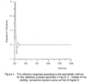
- Figure 4 represents the ray-theoretical solution for the same circumstance.
- Figure 5 depicts the difference between the wave-theoretical and the ray-theoretical solution. It is evident that the magnitude of the maximum difference is a substantial fraction ( ⁇ 13%) of the maximum of the wave-theoretical solution. Thus, the ray-theoretical solution lacks efficacy in this instance.
- Figure 6 depicts the complete wave-theoretical solution for a point acoustic source-reflector ( Figure 1 ) specified in the caption of Figure 6 and the source-time function depicted in Figure 2 .
- the only difference with the source-reflector parameters specified in Figure 3 is that h, the depth to the reflector from the source/receiver point, is 1500 m in this case, in contrast with a depth of 300 m as depicted in Figure 3 .
- Figure 7 shows the ray-theoretical solution for the circumstance represented in Figure 6 .
- Figure 8 depicts the difference between the wave-theoretical and the ray-theoretical solution.
- the magnitude of the maximum difference is only a negligible fraction ( ⁇ 3%) of the maximum of the wave-theoretical solution.
- the ray-theoretical solution is adequate in this case. It is important to note that a greater value of h in this case leading to an increased radius of curvature of the incident wavefront at the reflector has made inappreciable the difference between the wave-theoretical and the ray-theoretical solution.
- the formula contains two distinct terms, the first, i.e., R 8 ⁇ h ⁇ t ⁇ ⁇ representing the ray-theoretical solution and the second, i.e., R 8 ⁇ h ⁇ 2 ⁇ 2 H t ⁇ ⁇ t 3 representing the non-raytheoretical solution, rendering assessment of the relative importance of the two terms rather easy.
Landscapes
- Engineering & Computer Science (AREA)
- Remote Sensing (AREA)
- Physics & Mathematics (AREA)
- Life Sciences & Earth Sciences (AREA)
- Geology (AREA)
- Environmental & Geological Engineering (AREA)
- Acoustics & Sound (AREA)
- General Life Sciences & Earth Sciences (AREA)
- General Physics & Mathematics (AREA)
- Geophysics (AREA)
- Geophysics And Detection Of Objects (AREA)
- Measurement Of Mechanical Vibrations Or Ultrasonic Waves (AREA)
- Aerials With Secondary Devices (AREA)
Claims (5)
- Un procédé mis en oeuvre par ordinateur permettant de déterminer une réponse impulsionnelle [us(t)] et une réponse de réflexion [r(t)] d'un réflecteur acoustique plan à un décalage nul dû à une source acoustique ponctuelle en variant des paramètres constitués d'une vitesse d'onde de référence à laquelle une perturbation de la vitesse a lieu (c), un changement de la vitesse d'onde sur un réflecteur (Δc), un coefficient de réflexion-onde-plan d'un réflecteur pour une incidence normale (R), une profondeur au réflecteur depuis le point de source/récepteur (h) et la fonction source-temps s(t), en employant la méthode de Fourier, dans lequel un paramètre de perturbation est substitué en termes de vitesse d'onde de référence et de changement de la vitesse d'onde à une interface de plan infini sur laquelle la vitesse d'onde change de la vitesse d'onde de référence à une somme de la vitesse d'onde de référence et du changement de la vitesse d'onde, ce qui est suivi de l'élimination des restrictions de l'approximation de Born, le procédé étant utile pour des applications sismologiques, le procédé comprenant les étapes consistant à :i) saisir la distance du réflecteur (h), la vitesse d'onde de référence (c), le changement de la vitesse d'onde (Δc), la fonction source-temps s(t) et le temps de troncature de la réponse impulsionnelle d'un réflecteur (T) dans l'équation A ;
 ii) obtenir une réponse impulsionnelle us(t) d'un réflecteur acoustique plan à un décalage nul dû à une source acoustique ponctuelle selon
 R = Δc/ (2c+Δc);t = temps d'observation qui commence à l'apparition de la source ;δ(t) = fonction delta Dirac ;c = vitesse d'onde de référence ;Δc = changement de la vitesse d'onde ;h = distance la plus courte entre la source et le réflecteur ;τ = 2h/c ;H = fonction de Heaviside, désignée par H (t - τ) et est définie par
 iii) obtenir une réponse de réflexion [r(t)] d'un réflecteur acoustique plan à un décalage nul dû à une source acoustique ponctuelle décrite par la fonction source-temps s(t), à partir de l'expression obtenue dans l'Equation B :
 τ = 2h/c ; et * désigne une convolution ;H = fonction de Heaviside ;t = temps d'observation qui commence à l'apparition de la source ;s(t) = fonction source-temps ;c = vitesse d'onde de référence ;Δc = changement de la vitesse d'onde ; eth = distance la plus courte entre la source et le réflecteur.
 - Un procédé permettant de déterminer la réponse impulsionnelle [us(t)] et une réponse de réflexion [r(t)] d'un réflecteur acoustique plan selon la revendication 1, dans lequel la réponse de réflexion à décalage nul d'un réflecteur circulaire est calculée en tenant compte des observations au niveau de son axe central et jusqu'à un laps de temps limité.
- Un procédé permettant de déterminer la réponse impulsionnelle [us(t)] et une réponse de réflexion [r(t)] d'un réflecteur acoustique plan selon la revendication 1 ou la revendication 2, dans lequel la section sismique à décalage nul exact est calculée en raison d'un réflecteur incliné ou horizontal planaire pour valider les algorithmes d'inversion et de migration sismique sismique.
- Un procédé permettant de déterminer la réponse impulsionnelle [us(t)] et une réponse de réflexion [r(t)] d'un réflecteur acoustique plan selon l'une quelconque des revendications 1 à 3, dans lequel ledit procédé valide une interprétation d'un réflecteur en tant que structure planaire.
- Un procédé permettant de déterminer la réponse impulsionnelle [us(t)] et une réponse de réflexion [r(t)] d'un réflecteur acoustique plan selon l'une quelconque des revendications 1 à 4, dans lequel ledit procédé calcule la fonction sismique source-temps s(t) en introduisant une réponse de réflexion à décalage nul d'un réflecteur plan.
Applications Claiming Priority (2)
| Application Number | Priority Date | Filing Date | Title |
|---|---|---|---|
| IN2626DE2006 | 2006-12-07 | ||
| PCT/IN2007/000071 WO2008068769A1 (fr) | 2006-12-07 | 2007-02-21 | Procédé pour calculer une réponse impulsionnelle exacte d'un réflecteur acoustique plan à un décalage nul dû à une source acoustique ponctuelle |
Publications (2)
| Publication Number | Publication Date |
|---|---|
| EP2089738A1 EP2089738A1 (fr) | 2009-08-19 |
| EP2089738B1 true EP2089738B1 (fr) | 2019-01-02 |
Family
ID=39226987
Family Applications (1)
| Application Number | Title | Priority Date | Filing Date |
|---|---|---|---|
| EP07736532.8A Not-in-force EP2089738B1 (fr) | 2006-12-07 | 2007-02-21 | Procédé pour calculer une réponse impulsionnelle exacte d'un réflecteur acoustique plan à un décalage nul dû à une source acoustique ponctuelle |
Country Status (8)
| Country | Link |
|---|---|
| US (1) | US7940601B2 (fr) |
| EP (1) | EP2089738B1 (fr) |
| AU (1) | AU2007330350A1 (fr) |
| CA (1) | CA2659782C (fr) |
| MX (1) | MX2009001681A (fr) |
| NO (1) | NO20092590L (fr) |
| RU (1) | RU2008151147A (fr) |
| WO (1) | WO2008068769A1 (fr) |
Families Citing this family (30)
| Publication number | Priority date | Publication date | Assignee | Title |
|---|---|---|---|---|
| US8694299B2 (en) | 2010-05-07 | 2014-04-08 | Exxonmobil Upstream Research Company | Artifact reduction in iterative inversion of geophysical data |
| CN103703391B (zh) | 2011-03-30 | 2017-05-17 | 埃克森美孚上游研究公司 | 使用频谱整形的全波场反演的系统和计算机实施的方法 |
| CA2825469C (fr) | 2011-03-31 | 2017-06-13 | Exxonmobil Upstream Research Company | Procede d'estimation d'ondelettes et predictions multiples lors d'une inversion d'un champ d'ondelettes complet |
| ES2640824T3 (es) | 2011-09-02 | 2017-11-06 | Exxonmobil Upstream Research Company | Utilización de la proyección sobre conjuntos convexos para limitar la inversión del campo de onda completa |
| US9176930B2 (en) | 2011-11-29 | 2015-11-03 | Exxonmobil Upstream Research Company | Methods for approximating hessian times vector operation in full wavefield inversion |
| MY170622A (en) | 2012-03-08 | 2019-08-21 | Exxonmobil Upstream Res Co | Orthogonal source and receiver encoding |
| CA2892041C (fr) | 2012-11-28 | 2018-02-27 | Exxonmobil Upstream Research Company | Tomographie fondee sur le facteur de qualite q de donnees sismiques de reflexion |
| CA2909105C (fr) | 2013-05-24 | 2018-08-28 | Ke Wang | Inversion multiparametrique par fwi elastique dependante au decalage |
| US10459117B2 (en) | 2013-06-03 | 2019-10-29 | Exxonmobil Upstream Research Company | Extended subspace method for cross-talk mitigation in multi-parameter inversion |
| US9702998B2 (en) | 2013-07-08 | 2017-07-11 | Exxonmobil Upstream Research Company | Full-wavefield inversion of primaries and multiples in marine environment |
| DK3036566T3 (en) | 2013-08-23 | 2018-07-23 | Exxonmobil Upstream Res Co | SIMILAR SOURCE APPLICATION DURING BOTH SEISMIC COLLECTION AND SEISMIC INVERSION |
| US10036818B2 (en) | 2013-09-06 | 2018-07-31 | Exxonmobil Upstream Research Company | Accelerating full wavefield inversion with nonstationary point-spread functions |
| US9910189B2 (en) | 2014-04-09 | 2018-03-06 | Exxonmobil Upstream Research Company | Method for fast line search in frequency domain FWI |
| EP3140675A1 (fr) | 2014-05-09 | 2017-03-15 | Exxonmobil Upstream Research Company | Procédés efficaces de recherche du pas optimal pour inversion de champ d'ondes complet à paramètres multiples |
| US10185046B2 (en) | 2014-06-09 | 2019-01-22 | Exxonmobil Upstream Research Company | Method for temporal dispersion correction for seismic simulation, RTM and FWI |
| MX362753B (es) | 2014-06-17 | 2019-02-07 | Exxonmobil Upstream Res Co | Inversion rapida de campo de ondas completo viscoacustico y viscoelastico. |
| US10838092B2 (en) | 2014-07-24 | 2020-11-17 | Exxonmobil Upstream Research Company | Estimating multiple subsurface parameters by cascaded inversion of wavefield components |
| US10422899B2 (en) | 2014-07-30 | 2019-09-24 | Exxonmobil Upstream Research Company | Harmonic encoding for FWI |
| US10386511B2 (en) | 2014-10-03 | 2019-08-20 | Exxonmobil Upstream Research Company | Seismic survey design using full wavefield inversion |
| US9977141B2 (en) | 2014-10-20 | 2018-05-22 | Exxonmobil Upstream Research Company | Velocity tomography using property scans |
| US11163092B2 (en) | 2014-12-18 | 2021-11-02 | Exxonmobil Upstream Research Company | Scalable scheduling of parallel iterative seismic jobs |
| US10520618B2 (en) | 2015-02-04 | 2019-12-31 | ExxohnMobil Upstream Research Company | Poynting vector minimal reflection boundary conditions |
| EP3256886B1 (fr) | 2015-02-13 | 2020-01-29 | Exxonmobil Upstream Research Company | Condition de limite d'absorption efficace et stable dans des calculs à différence finie |
| AU2015383134B2 (en) | 2015-02-17 | 2018-01-25 | Exxonmobil Upstream Research Company | Multistage full wavefield inversion process that generates a multiple free data set |
| US10416327B2 (en) | 2015-06-04 | 2019-09-17 | Exxonmobil Upstream Research Company | Method for generating multiple free seismic images |
| US10838093B2 (en) | 2015-07-02 | 2020-11-17 | Exxonmobil Upstream Research Company | Krylov-space-based quasi-newton preconditioner for full-wavefield inversion |
| RU2693495C1 (ru) | 2015-10-02 | 2019-07-03 | Эксонмобил Апстрим Рисерч Компани | Полная инверсия волнового поля с компенсацией показателя качества |
| US10520619B2 (en) | 2015-10-15 | 2019-12-31 | Exxonmobil Upstream Research Company | FWI model domain angle stacks with amplitude preservation |
| US10768324B2 (en) | 2016-05-19 | 2020-09-08 | Exxonmobil Upstream Research Company | Method to predict pore pressure and seal integrity using full wavefield inversion |
| RU2760508C1 (ru) * | 2020-10-01 | 2021-11-25 | Общество с ограниченной ответственностью «Научно-производственный центр неразрушающего контроля «ЭХО+» | Способ определения типа отражателя по амплитуде рассеянных им ультразвуковых импульсов |
Family Cites Families (2)
| Publication number | Priority date | Publication date | Assignee | Title |
|---|---|---|---|---|
| GB2322704B (en) * | 1994-07-07 | 1998-12-09 | Geco As | Method of Processing seismic data |
| NO320271B1 (no) * | 2000-05-26 | 2005-11-14 | Norsar V Daglig Leder | Fremgangsmate og anordning for a finne refleksjonsstyrken til reflektorer i undergrunnen mens refleksjonskoeffisienten for en malhorisont holdes konstant |
-
2007
- 2007-02-21 EP EP07736532.8A patent/EP2089738B1/fr not_active Not-in-force
- 2007-02-21 MX MX2009001681A patent/MX2009001681A/es active IP Right Grant
- 2007-02-21 WO PCT/IN2007/000071 patent/WO2008068769A1/fr not_active Ceased
- 2007-02-21 RU RU2008151147/28A patent/RU2008151147A/ru unknown
- 2007-02-21 CA CA2659782A patent/CA2659782C/fr active Active
- 2007-02-21 AU AU2007330350A patent/AU2007330350A1/en not_active Abandoned
- 2007-02-26 US US11/711,469 patent/US7940601B2/en not_active Expired - Fee Related
-
2009
- 2009-07-07 NO NO20092590A patent/NO20092590L/no not_active Application Discontinuation
Non-Patent Citations (1)
| Title |
|---|
| None * |
Also Published As
| Publication number | Publication date |
|---|---|
| WO2008068769A1 (fr) | 2008-06-12 |
| CA2659782A1 (fr) | 2008-06-12 |
| CA2659782C (fr) | 2015-04-21 |
| MX2009001681A (es) | 2009-02-26 |
| US7940601B2 (en) | 2011-05-10 |
| US20080137477A1 (en) | 2008-06-12 |
| AU2007330350A1 (en) | 2008-06-12 |
| RU2008151147A (ru) | 2010-06-27 |
| EP2089738A1 (fr) | 2009-08-19 |
| NO20092590L (no) | 2009-09-04 |
Similar Documents
| Publication | Publication Date | Title |
|---|---|---|
| EP2089738B1 (fr) | Procédé pour calculer une réponse impulsionnelle exacte d'un réflecteur acoustique plan à un décalage nul dû à une source acoustique ponctuelle | |
| Górszczyk et al. | Toward a robust workflow for deep crustal imaging by FWI of OBS data: The eastern Nankai Trough revisited | |
| US7082368B2 (en) | Seismic event correlation and Vp-Vs estimation | |
| EP2335093B1 (fr) | Estimation des propriétés d'un sol à l'aide des formes d'onde des ondes sismiques de surface | |
| US6820010B1 (en) | Method for determining shear-wave velocity model for depth migration of mode-converted data | |
| US7746726B2 (en) | Method for processing borehole seismic data | |
| US9158018B2 (en) | Waveform inversion using a response of forward modeling | |
| US20100118652A1 (en) | Determination of depth moveout and of residual radii of curvature in the common angle domain | |
| US20030117894A1 (en) | System and method for estimating seismic material properties | |
| US20040015296A1 (en) | Seismic processing with general non-hyperbolic travel-time corrections | |
| CN104614763A (zh) | 基于反射率法的多波avo储层弹性参数反演方法及系统 | |
| US12320937B2 (en) | Full-waveform inversion with elastic mitigation using acoustic anisotropy | |
| Cheng | Anelastic attenuation in seismic data: modeling, measurement, and correction | |
| US20150301210A1 (en) | Methods and systems to separate wavefields using pressure wavefield data | |
| Xia et al. | Reflection tomography by depth warping: A case study across the Java trench | |
| Margrave et al. | Full waveform inversion with wave equation migration and well control | |
| Wenzel | Processing of wide-angle vibroseis data | |
| Saengduean | Wavefield Reconstruction Using Seismic Interferometry and Compressive Sensing | |
| Eaton | Seismic migration/inversion for transversely isotropic elastic media | |
| Romahn Reynoso | Well-log validated waveform inversion of reflection seismic data | |
| Carrion | Velocity analysis from large offset seismic records | |
| Chon et al. | Offset VSP imaging with elastic reverse time migration | |
| Failly et al. | Lower crustal reflectivity from waveform inversion | |
| Moser et al. | Born inversion in realistic backgrounds by means of recursive Green’s functions | |
| Ihaka | Statistical aspects of earthquake source parameter estimation in the presence of signal generated noise |
Legal Events
| Date | Code | Title | Description |
|---|---|---|---|
| PUAI | Public reference made under article 153(3) epc to a published international application that has entered the european phase |
Free format text: ORIGINAL CODE: 0009012 |
|
| 17P | Request for examination filed |
Effective date: 20081128 |
|
| AK | Designated contracting states |
Kind code of ref document: A1 Designated state(s): AT BE BG CH CY CZ DE DK EE ES FI FR GB GR HU IE IS IT LI LT LU LV MC NL PL PT RO SE SI SK TR |
|
| DAX | Request for extension of the european patent (deleted) | ||
| 17Q | First examination report despatched |
Effective date: 20160107 |
|
| RBV | Designated contracting states (corrected) |
Designated state(s): AT BE BG CH CY CZ DE DK EE ES FI FR GB GR HU IE IS IT LI LT LU LV MC NL PL PT RO SE SI SK TR |
|
| GRAJ | Information related to disapproval of communication of intention to grant by the applicant or resumption of examination proceedings by the epo deleted |
Free format text: ORIGINAL CODE: EPIDOSDIGR1 |
|
| GRAP | Despatch of communication of intention to grant a patent |
Free format text: ORIGINAL CODE: EPIDOSNIGR1 |
|
| RBV | Designated contracting states (corrected) |
Designated state(s): GB NL |
|
| REG | Reference to a national code |
Ref country code: DE Ref legal event code: R108 |
|
| GRAP | Despatch of communication of intention to grant a patent |
Free format text: ORIGINAL CODE: EPIDOSNIGR1 |
|
| INTG | Intention to grant announced |
Effective date: 20180713 |
|
| INTG | Intention to grant announced |
Effective date: 20180718 |
|
| GRAS | Grant fee paid |
Free format text: ORIGINAL CODE: EPIDOSNIGR3 |
|
| GRAA | (expected) grant |
Free format text: ORIGINAL CODE: 0009210 |
|
| AK | Designated contracting states |
Kind code of ref document: B1 Designated state(s): GB NL |
|
| REG | Reference to a national code |
Ref country code: GB Ref legal event code: FG4D |
|
| REG | Reference to a national code |
Ref country code: NL Ref legal event code: MP Effective date: 20190102 |
|
| PG25 | Lapsed in a contracting state [announced via postgrant information from national office to epo] |
Ref country code: NL Free format text: LAPSE BECAUSE OF FAILURE TO SUBMIT A TRANSLATION OF THE DESCRIPTION OR TO PAY THE FEE WITHIN THE PRESCRIBED TIME-LIMIT Effective date: 20190102 |
|
| PLBE | No opposition filed within time limit |
Free format text: ORIGINAL CODE: 0009261 |
|
| STAA | Information on the status of an ep patent application or granted ep patent |
Free format text: STATUS: NO OPPOSITION FILED WITHIN TIME LIMIT |
|
| 26N | No opposition filed |
Effective date: 20191003 |
|
| GBPC | Gb: european patent ceased through non-payment of renewal fee |
Effective date: 20190402 |
|
| PG25 | Lapsed in a contracting state [announced via postgrant information from national office to epo] |
Ref country code: GB Free format text: LAPSE BECAUSE OF NON-PAYMENT OF DUE FEES Effective date: 20190402 |