EP2089944B1 - Zündkerze, insbesondere für hohe brennraumdrücke - Google Patents
Zündkerze, insbesondere für hohe brennraumdrücke Download PDFInfo
- Publication number
- EP2089944B1 EP2089944B1 EP07787409A EP07787409A EP2089944B1 EP 2089944 B1 EP2089944 B1 EP 2089944B1 EP 07787409 A EP07787409 A EP 07787409A EP 07787409 A EP07787409 A EP 07787409A EP 2089944 B1 EP2089944 B1 EP 2089944B1
- Authority
- EP
- European Patent Office
- Prior art keywords
- insulator
- spark plug
- housing
- plug according
- conductive planar
- Prior art date
- Legal status (The legal status is an assumption and is not a legal conclusion. Google has not performed a legal analysis and makes no representation as to the accuracy of the status listed.)
- Not-in-force
Links
- 238000002485 combustion reaction Methods 0.000 title description 15
- 239000012212 insulator Substances 0.000 claims abstract description 50
- 239000011248 coating agent Substances 0.000 claims description 19
- 238000000576 coating method Methods 0.000 claims description 19
- 238000007789 sealing Methods 0.000 claims description 5
- 229910052709 silver Inorganic materials 0.000 claims description 5
- 239000004332 silver Substances 0.000 claims description 5
- PXHVJJICTQNCMI-UHFFFAOYSA-N Nickel Chemical compound [Ni] PXHVJJICTQNCMI-UHFFFAOYSA-N 0.000 claims description 4
- PCHJSUWPFVWCPO-UHFFFAOYSA-N gold Chemical compound [Au] PCHJSUWPFVWCPO-UHFFFAOYSA-N 0.000 claims description 4
- 230000003647 oxidation Effects 0.000 claims description 4
- 238000007254 oxidation reaction Methods 0.000 claims description 4
- BASFCYQUMIYNBI-UHFFFAOYSA-N platinum Chemical compound [Pt] BASFCYQUMIYNBI-UHFFFAOYSA-N 0.000 claims description 4
- 239000010970 precious metal Substances 0.000 claims description 4
- 239000000956 alloy Substances 0.000 claims description 3
- 229910045601 alloy Inorganic materials 0.000 claims description 3
- OKTJSMMVPCPJKN-UHFFFAOYSA-N Carbon Chemical compound [C] OKTJSMMVPCPJKN-UHFFFAOYSA-N 0.000 claims description 2
- 229910052799 carbon Inorganic materials 0.000 claims description 2
- 239000004020 conductor Substances 0.000 claims description 2
- 229910052737 gold Inorganic materials 0.000 claims description 2
- 239000010931 gold Substances 0.000 claims description 2
- 229910052741 iridium Inorganic materials 0.000 claims description 2
- GKOZUEZYRPOHIO-UHFFFAOYSA-N iridium atom Chemical compound [Ir] GKOZUEZYRPOHIO-UHFFFAOYSA-N 0.000 claims description 2
- 229910052759 nickel Inorganic materials 0.000 claims description 2
- 229910052697 platinum Inorganic materials 0.000 claims description 2
- 229910052703 rhodium Inorganic materials 0.000 claims description 2
- 239000010948 rhodium Substances 0.000 claims description 2
- MHOVAHRLVXNVSD-UHFFFAOYSA-N rhodium atom Chemical compound [Rh] MHOVAHRLVXNVSD-UHFFFAOYSA-N 0.000 claims description 2
- 229910052715 tantalum Inorganic materials 0.000 claims description 2
- GUVRBAGPIYLISA-UHFFFAOYSA-N tantalum atom Chemical compound [Ta] GUVRBAGPIYLISA-UHFFFAOYSA-N 0.000 claims description 2
- 239000011888 foil Substances 0.000 claims 1
- 239000004922 lacquer Substances 0.000 claims 1
- 230000000241 respiratory effect Effects 0.000 description 6
- 230000005684 electric field Effects 0.000 description 5
- BQCADISMDOOEFD-UHFFFAOYSA-N Silver Chemical compound [Ag] BQCADISMDOOEFD-UHFFFAOYSA-N 0.000 description 4
- 230000015572 biosynthetic process Effects 0.000 description 3
- 238000010586 diagram Methods 0.000 description 3
- 239000003973 paint Substances 0.000 description 3
- 238000007906 compression Methods 0.000 description 2
- 238000009413 insulation Methods 0.000 description 2
- QVGXLLKOCUKJST-UHFFFAOYSA-N atomic oxygen Chemical compound [O] QVGXLLKOCUKJST-UHFFFAOYSA-N 0.000 description 1
- 230000006835 compression Effects 0.000 description 1
- 230000001419 dependent effect Effects 0.000 description 1
- 230000002542 deteriorative effect Effects 0.000 description 1
- 238000011161 development Methods 0.000 description 1
- 230000018109 developmental process Effects 0.000 description 1
- 230000009191 jumping Effects 0.000 description 1
- 239000000463 material Substances 0.000 description 1
- 238000000034 method Methods 0.000 description 1
- 239000000203 mixture Substances 0.000 description 1
- 229910000510 noble metal Inorganic materials 0.000 description 1
- 229910052760 oxygen Inorganic materials 0.000 description 1
- 239000001301 oxygen Substances 0.000 description 1
- 230000029058 respiratory gaseous exchange Effects 0.000 description 1
- 238000005096 rolling process Methods 0.000 description 1
- 238000005507 spraying Methods 0.000 description 1
- 230000007704 transition Effects 0.000 description 1
Images

Classifications
-
- H—ELECTRICITY
- H01—ELECTRIC ELEMENTS
- H01T—SPARK GAPS; OVERVOLTAGE ARRESTERS USING SPARK GAPS; SPARKING PLUGS; CORONA DEVICES; GENERATING IONS TO BE INTRODUCED INTO NON-ENCLOSED GASES
- H01T13/00—Sparking plugs
- H01T13/20—Sparking plugs characterised by features of the electrodes or insulation
- H01T13/36—Sparking plugs characterised by features of the electrodes or insulation characterised by the joint between insulation and body, e.g. using cement
-
- H—ELECTRICITY
- H01—ELECTRIC ELEMENTS
- H01T—SPARK GAPS; OVERVOLTAGE ARRESTERS USING SPARK GAPS; SPARKING PLUGS; CORONA DEVICES; GENERATING IONS TO BE INTRODUCED INTO NON-ENCLOSED GASES
- H01T13/00—Sparking plugs
- H01T13/20—Sparking plugs characterised by features of the electrodes or insulation
- H01T13/38—Selection of materials for insulation
Definitions
- the present invention relates to a spark plug for internal combustion engines, which is designed in particular for use in combustion chambers with high pressure.
- Spark plugs are known from the prior art in different configurations.
- the known spark plugs have basically proven themselves for use in internal combustion engines.
- the pressures in the combustion chamber at the time of ignition are getting larger, since the internal combustion engines are increasingly charged and operated with high compression.
- the formation of sliding sparks during ignition may occur, which in particular also extends into a respiratory chamber of the spark plug, which is formed between a tapering region of the insulator and a housing of the spark plug at the combustion chamber end of the spark plug.
- Such sliding sparks lead in the homogeneous operation of the internal combustion engine to a turbulent engine run. In stratified operation of the internal combustion engine and in operating states with inhomogeneous mixture distribution, such. During low-temperature starts, sliding sparks cause frequent misfires.
- a spark plug according to the preamble of claim 1 is made EP-A-1 557 918 known.
- the spark plug according to the invention with the features of claim 1 has the advantage that it prevents the formation of sliding sparks. This allows the spark plug according to the invention in particular in Brennkrafhnaschinen with high Press, such as charged and / or high-compression engines used.
- the spark plug according to the invention has a long service life and can be produced easily and inexpensively.
- This is inventively achieved in that on the insulator of the spark plug, a conductive sheet-like element is arranged, which is in electrical contact with the housing.
- the insulator surface is set to the electrical potential of the housing.
- the housing is usually grounded.
- the conductive, sheet-like element is preferably formed as extending completely around the insulator band.
- an emergence of electric fields in the critical region of the respiratory space between the insulation and the housing can be reliably prevented.
- the conductive, sheet-like element is arranged in the region of a sealing seat between the housing and the insulator. As a result, a secure contact can be achieved.
- the spark plug comprises a sealing ring, which is arranged between the housing and the insulator, and the sealing ring is made of an electrically conductive material.
- the conductive, sheet-like element according to the invention is arranged on a region of the insulator which is positioned at the level of the sealing ring.
- the conductive, sheet-like element has a maximum thickness of 100 microns.
- the conductive sheet-like member is further preferably provided with a constant thickness. This upper limit of the thickness of the element has the advantage that a simple attachment is guaranteed. It should also be noted that as the layer thickness increases, stresses in the material significantly increase, thereby deteriorating the attachment of the element.
- the thickness of the conductive, sheet-like element is in the range of about 50 microns to about 80 microns.
- the conductive, sheet-like element is arranged on the insulator at a region of the insulator, which is arranged in the mounted state at the level of an inner, circumferential web of the housing.
- the conductive, sheet-like element on the insulator covers at least 70% of the surface of the insulator, which is directed towards the inner web of the housing in the radial direction of the spark plug.
- the conductive sheet-like element starting from a contact point between the insulator and the housing, covers a region of the insulator in the direction of its end surface on which the electrodes are arranged, the region provided with the conductive, planar element being a maximum of 50%, preferably 30 % of the distance between the contact point and the end face of the insulator.
- the conductive sheet-like member covers an area of at least 70% of a portion of the insulator having a pitch of less than or equal to 0.5mm from the inner surface of the housing. This also ensures that the critical area for the emergence of sliding sparks in the working space is made field-free.
- the conductive, sheet-like element is a conductive coating. This is easy and inexpensive to apply and has only a low density.
- the coating is a conductive ink, which has an electrical conductivity.
- the conductive ink includes preferably a precious metal, in particular silver and / or platinum and / or gold unct / or iridium and / or rhodium, and / or tantalum and / or nickel and / or carbon or any oxidation-resistant alloy thereof.
- the oxidation resistance is important because high temperatures and atmospheric oxygen are present in the combustion chamber.
- a thin tape e.g. Gold leaf or other precious metal-containing film can be used.
- FIGS. 1 and 2 a spark plug 1 according to an embodiment of the invention described in detail.
- the spark plug 1 comprises a housing 2 which has an external thread 2a, with which the spark plug 1 is fastened to a component of an internal combustion engine.
- the spark plug 1 further comprises an insulator 3 with a combustion chamber side end face 3a.
- a center electrode 4 is arranged, which is arranged in the longitudinal direction XX of the spark plug.
- a ground electrode 5 is connected to the housing 2.
- a breathing chamber 6 is formed between the insulator 3 and the housing 2.
- the respiratory space 6 is annular and tapers from the electrode-side end of the spark plug.
- the web 2b has an annular shape and a seal 9 is arranged at a step transition between the web 2b and the inside of the housing between the housing 2 and the insulator 3.
- a coating 7 made of a silver conductive paint is further applied at the level of the web 2b.
- the silver conductive ink can be applied to the insulator 3, for example, by spraying or rolling.
- the contact point 8 is an electrically conductive contact between the housing 2 and the coating 7, so that it is achieved that the outer surface of the insulator. 3 is placed in the region of the respiratory space 6 to the electrical potential of the housing.
- electric fields can be prevented from building up between the insulator 3 and the inside of the housing 2, which can lead to a sliding spark jumping over the end face 3a of the insulator 3 into the respiratory space 6 during the ignition time.
- the conductive coating 7 eliminates these electric fields in the region of the inner web 2b of the housing 2.
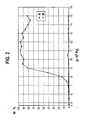
- FIG. 2 shows a diagram showing a comparison of a spark plug with an insulator without coating according to the prior art and a spark plug according to the invention with a coating comprising silver conductive paint having insulator.
- the curve of the spark plug is marked with an insulator without coating with "N” and the curve of the spark plug with an insulator with coating marked with "M”.
- "W” indicates the probability of a sliding spark in%.
- the spark plug according to the invention even at very high pressures only a minimal probability of the emergence of a sliding spark.
- the coating 7 is provided on the insulator 3 at a width B in the longitudinal direction XX of the spark plug starting from the contact point 8, wherein a ratio of the width B to a distance A from the contact point 8 to the end face 3a of the insulator 3 is about 1: 4.
- the coating 7 is formed over a surface area starting from the contact point 8 of approximately 25% of the insulator surface from the contact point 8 to the end face 3a.
- the coating 7 is provided completely over the entire width of the web 2b.
- An overlap of the coating 7 in the region of the web 2b should amount to at least 70% of the web width to the area prone to the unwanted pre-discharges between the insulator 3 and the housing 2 to make field-free. It should also be noted that the coating 7 on the insulator 3 should be at most 50%, particularly preferably at most 30%, of the distance A between the contact point 8 and the end face 3a.
- the coating used is preferably a conductive paint which comprises a noble metal or an oxidation-resistant conductive alloy, since very high temperatures often occur in the combustion chamber.
- the present invention can be used in all known fields of use of spark plugs, but is particularly preferably used when high pressures occur in combustion chambers.
Landscapes
- Spark Plugs (AREA)
Abstract
Description
- Die vorliegende Erfindung betrifft eine Zündkerze für Brennkraftmaschinen, welche insbesondere zur Verwendung in Brennräumen mit hohem Druck ausgelegt ist.
- Zündkerzen sind aus dem Stand der Technik in unterschiedlichen Ausgestaltungen bekannt. Die bekannten Zündkerzen haben sich grundsätzlich zur Verwendung in Brennkraftmaschinen bewährt. Allerdings werden in jüngster Zeit die Drücke im Brennraum zum Zündzeitpunkt immer größer, da die Brennkraftmaschinen verstärkt aufgeladen werden und mit hoher Verdichtung betrieben werden. Dabei kann es insbesondere bei hohen Drücken zur Entstehung von Gleitfunken bei der Zündung kommen, welche insbesondere auch bis in einen Atmungsraum der Zündkerze, welcher zwischen einem sich verjüngenden Bereich des Isolators und einem Gehäuse der Zündkerze an dem brennraumseitigen Ende der Zündkerze gebildet ist. Derartige Gleitfunken führen im homogenen Betrieb der Brennkraftmaschine zu einem unruhigen Motorlauf. Im Schichtbetrieb der Brennkraftmaschine und bei Betriebszuständen mit inhomogener Gemischverteilung, wie z.B. bei Tieftemperaturstarts, bewirken Gleitfunken gehäuft auftretende Verbrennungsaussetzer.
- In der
DE 196 50 724 B4 wurde zur Reduzierung von Gleitfunken vorgeschlagen, einen Elektrodenabstand zwischen der Mittelelektrode und der Masseelektrode derart vorzusehen, dass dieser Elektrodenabstand kleiner als ein Abstand der Mittelelektrode zum Gehäuse ist. Die hierbei vorgeschlagenen geometrischen Anordnungen der Elektroden können jedoch häufig aufgrund von bauraumbedingen Vorgaben nicht eingehalten werden. - Eine Zündkerze, gemäss Oberbegriff des Anspruchs 1 ist aus
EP-A-1 557 918 bekannt. - Die erfindungsgemäße Zündkerze mit den Merkmalen des Patentanspruchs 1 weist demgegenüber den Vorteil auf, dass sie die Entstehung von Gleitfunken verhindert. Dadurch kann die erfindungsgemäße Zündkerze insbesondere in Brennkrafhnaschinen mit hohen Drücken, wie z.B. aufgeladenen und/oder hochverdichteten Motoren, verwendet werden. Die erfindungsgemäße Zündkerze weist dabei eine hohe Lebensdauer und kann einfach und kostengünstig hergestellt werden. Dies wird erfindungsgemäß dadurch erreicht, dass auf dem Isolator der Zündkerze ein leitfähiges flächenartiges Element angeordnet ist, welche mit dem Gehäuse elektrisch in Kontakt steht. Dadurch wird erfindungsgemäß erreicht, dass die Isolatoroberfläche auf das elektrische Potential des Gehäuses gelegt wird. Das Gehäuse ist dabei üblicherweise geerdet. Durch diese relativ einfache erfindungsgemäße Maßnahme können elektrische Felder, welche im Atmungsraum zwischen der sich verjüngenden Isolation und dem Gehäuse bei konventionellen Zündkerzen vorhanden sind, eliminiert werden. Dadurch kann auch bei hohen Drücken die Erzeugung von Gleitfunken verhindert werden. Ferner können Teilentladungen im Gehäusestegbereich vermieden werden und somit auch elektromagnetische Störpulse unterdrückt werden.
- Die Unteransprüche zeigen bevorzugte Weiterbildungen der Erfindung.
- Das leitfähige, flächenartige Element ist vorzugsweise als vollständig um den Isolator verlaufendes Band ausgebildet. Dadurch kann sicher eine Entstehung elektrischer Felder im kritischen Bereich des Atmungsraums zwischen der Isolation und dem Gehäuse verhindert werden. Es sei angemerkt, dass es alternativ auch möglich ist, mehrere nur teilweise umlaufende Bereiche mit dem erfindungsgemäßen leitfähigen, flächenartigen Element zu versehen, wobei benachbarte Flächenclcinente nur in geringem Umfang voneinander beabstandet sind. Hierbei muss jedoch eine elektrische Verbindung jedes Elements zum Gehäuse vorhanden sein.
- Besonders bevorzugt ist das leitfähige, flächenartige Element im Bereich eines Dichtsitzes zwischen dem Gehäuse und dem Isolator angeordnet. Dadurch kann eine sichere Kontaktierung erreicht werden.
- Weiter bevorzugt umfasst die Zündkerze einen Dichtring, welcher zwischen dem Gehäuse und dem Isolator angeordnet ist, und der Dichtring ist aus einem elektrisch leitenden Material hergestellt. Das erfindungsgemäße leitfähige, flächenartige Element ist dabei an einem Bereich des Isolators angeordnet, welcher auf Höhe des Dichtrings positioniert ist.
- Gemäß einer weiteren bevorzugten Ausgestaltung der vorliegenden Erfindung weist das leitfähige, flächenartige Element eine Dicke von maximal 100 µm auf. Das leitfähige, flächenartige Element ist weiter bevorzugt mit einer konstanten Dicke vorgesehen. Diese Obergrenze der Dicke des Elements weist den Vorteil auf, dass eine einfache Befestigung gewährleistet ist. Es sei ferner angemerkt, dass mit einer größer werdenden Schichtdicke Spannungen im Material erheblich ansteigen, wodurch sich die Befestigung des Elements verschlechtert. Besonders bevorzugt liegt die Dicke des leitfähigen, flächenartigen Elements im Bereich von ca. 50 µm bis ca. 80 µm.
- Weiter bevorzugt ist das leitfähige, flächenartige Element am Isolator an einem Bereich des Isolators angeordnet, welcher im montierten Zustand auf Höhe eines inneren, umlaufenden Stegs des Gehäuses angeordnet ist. Vorzugweise überdeckt das leitfähige, flächenartige Element am Isolator dabei wenigstens 70% der Fläche des Isolators, welche zum inneren Steg des Gehäuses in Radialrichtung der Zündkerze gerichtet ist. Durch diese Maßnahme wird sichergestellt, dass der für die Bildung von elektrischen Feldern anfällige Raum zwischen dem inneren Steg des Gehäuse und dem Isolator zumindest zu 70% mit dem elektrisch leitenden Element überdeckt ist. Dadurch kann dieser für Vorentladungen anfällige Bereich feldfrei gemacht werden, so dass die Neigung zur Entstehung von Gleitfunken reduziert ist. Es sei ferner angemerkt, dass das leitfähige, flächenartige Element am Isolator nicht zu weit in Richtung der Elektroden reichen darf, da sich sonst eine Nebenanschlussanfälligkeit der Zündkerze wesentlich erhöht.
- Vorzugsweise bedeckt das leitfähige, flächenartige Element, ausgehend von einer Kontaktstelle zwischen Isolator und Gehäuse, einen Bereich des Isolators in Richtung von dessen Stirnfläche, an welcher die Elektroden angeordnet sind, wobei der mit dem leitfähigen, flächenartigen Element versehene Bereich maximal 50%, vorzugsweise 30% des Abstandes zwischen der Kontaktstelle und der Stirnfläche des Isolators ist.
- Vorzugsweise bedeckt das leitfähige, flächenartige Element eine Fläche von mindestens 70% eines Bereichs des Isolators, welcher zur Innenfläche des Gehäuses einen Abstand von kleiner gleich 0,5 mm aufweist. Dies stellt ebenfalls sicher, dass der für die Entstehung von Gleitfunken in den Arbeitsraum kritische Bereich feldfrei gemacht wird.
- Besonders bevorzugt ist das leitfähige, flächenartige Element eine leitfähige Beschichtung. Diese ist einfach und kostengünstig aufbringbar und weist nur eine geringe Dichte auf.
- Besonders bevorzugt ist die Beschichtung ein Leitlack, welcher eine elektrische Leitfähigkeit aufweist. Dies hat insbesondere den Vorteil, dass die Beschichtung besonders einfach und kostengünstig aufgebracht werden kann. Dabei ist es auch nicht notwendig, dass bisherige Montageverfahren von Zündkerzen geändert werden müssen. Der Leitlack umfasst vorzugsweise ein Edelmetall, insbesondere Silber und/oder Platin und/oder Gold unct/oder Iridium und/oder Rhodium, und/oder Tantal und/oder Nickel und/oder Kohlenstoff oder eine beliebige oxidationsbeständige Legierung hiervon. Die Oxidationsbeständigkeit ist wichtig, da im Brennraum hohe Temperaturen und Luftsauerstoff vorhanden sind.
- Als leitfähiges, flächenartiges Element kann auch ein dünnes Band bzw. eine dünne Folie, z.B. Blattgold oder eine andere Edelmetall-haltige Folie, verwendet werden.
- Nachfolgend wird ein bevorzugtes Ausführunolsbeispiel der Erfindung unter Bezugnahme auf die begleitende Zeichnung beschrieben. In der Zeichnung ist:
- Figur 1
- eine schematische, teilweise geschnittene Teilansicht einer Zündkerze gemäß einem Ausfiihrungsbeispiel der Erfindung und
- Figur 2
- ein Diagramm, welches die Wahrscheinlichkeit des Entstehens von Gleitfunken in Abhängigkeit vom Druck im Brennraum für eine erfindungsgemäße Zündkerze sowie eine Zündkerze des Standes der Technik zeigt.
- Nachfolgend wird unter Bezugnahme auf die
Figuren 1 und2 eine Zündkerze 1 gemäß einem Ausführungsbeispiel der Erfindung im Detail beschrieben. - Wie in
Figur 1 gezeigt, umfasst die Zündkerze 1 ein Gehäuse 2, welches ein Außengewinde 2a aufweist, mit welchem die Zündkerze 1 an einem Bauteil einer Brennkraftmaschine befestigt wird. Die Zündkerze 1 umfasst ferner einen Isolator 3 mit einer brennraumseitigen Stirnfläche 3a. Im Inneren des Isolators 3 ist eine Mittelelektrode 4 angeordnet, welche in Längsrichtung X-X der Zündkerze angeordnet ist. Eine Masseelektrode 5 ist mit dem Gehäuse 2 verbunden. - Wie aus
Figur 1 ersichtlich ist, ist zwischen dem Isolator 3 und dem Gehäuse 2 ein Atmungsraum 6 ausgebildet. Der Atmungsraum 6 ist ringförmig vorgesehen und verjüngt sich ausgehend vom Elektroden-seitigen Ende der Zündkerze. An der Innenseite des Gehäuses 2 ist ferner ein innerer umlaufender Steg 2b ausgebildet. Der Steg 2b weist eine ringförmige Gestalt auf und eine Dichtung 9 ist an einem Stufenübergang zwischen dem Steg 2b und der Innenseite des Gehäuses zwischen dem Gehäuse 2 und dem Isolator 3 angeordnet. - Am Isolator 3 ist ferner auf der Höhe des Stegs 2b eine Beschichtung 7 aus einem Silberleitlack aufgebracht. Der Silberleitlack kann beispielsweise durch Aufsprühen oder Aufwalzen auf den Isolator 3 aufgebracht werden. Im Bereich der Stufe am Steg 2b liegt eine ringförmige Kontaktstelle 8 zwischen dem Gehäuse 2 und der Beschichtung 7. Die Kontaktstelle 8 stellt einen elektrisch leitenden Kontakt zwischen dem Gehäuse 2 und der Beschichtung 7 dar, so dass erreicht wird, dass die Außenfläche des Isolators 3 im Bereich des Atmungsraums 6 auf das elektrische Potential des Gehäuses gelegt wird. Dadurch kann verhindert werden, dass sich zwischen dem Isolator 3 und der Innenseite des Gehäuses 2 elektrische Felder aufbauen, welche dazu führen können, dass während des Zündzeitpunkts ein Gleitfunken über die Stirnfläche 3a des Isolators 3 in den Atmungsraum 6 springt. Die leitfähige Beschichtung 7 eliminiert diese elektrischen Felder im Bereich des inneren Stegs 2b des Gehäuses 2. Somit kann erfindungsgemäß insbesondere bei hohen Drücken das Entstehen eines Gleitfunkens verhindert werden.
-
Figur 2 zeigt hierzu ein Diagramm, welches einen Vergleich einer Zündkerze mit einem Isolator ohne Beschichtung gemäß dem Stand der Technik sowie eine erfindungsgemäße Zündkerze mit einem eine Beschichtung aus Silberleitlack aufweisenden Isolator zeigt. InFigur 2 ist die Kurve der Zündkerze mit einem Isolator ohne Beschichtung mit "N" gekennzeichnet und die Kurve der Zündkerze mit einem Isolator mit Beschichtung mit "M" gekennzeichnet. "W" bezeichnet die Wahrscheinlichkeit für einen Gleitfunken in %. Wie aus dem Diagramm vonFigur 2 ersichtlich ist, weist die erfindungsgemäße Zündkerze auch bei sehr hohen Drücken nur eine minimale Wahrscheinlichkeit für die Entstehung eines Gleitfunkens auf. Im Unterschied dazu ist bei der Zündkerze nach dem Stand der Technik ein signifikanter Anstieg der Wahrscheinlichkeit für das Auftreten eines Gleitfunkens ab einem Druck von ca. 7 x 10⁵ Pascal ersichtlich. - Aus
Figur 1 ist ferner ersichtlich, dass die Beschichtung 7 auf dem Isolator 3 auf einer Breite B in Längsrichtung X-X der Zündkerze ausgehend von der Kontaktstelle 8 vorgesehen ist, wobei ein Verhältnis der Breite B zu einem Abstand A von der Kontaktstelle 8 zu der Stirnfläche 3a des Isolators 3 ungefähr 1:4 beträgt. Mit anderen Worten ist die Beschichtung 7 über einen Flächenbereich ausgehend von der Kontaktstelle 8 von ca. 25% der Isolatoroberfläche von der Kontaktstelle 8 bis zur Stirnfläche 3a gebildet. Wie ferner ausFigur 1 ersichtlich ist, ist dabei die Beschichtung 7 vollständig über die gesamte Breite des Stegs 2b vorgesehen. Eine Überdeckung der Beschichtung 7 im Bereich des Stegs 2b sollte dabei mindestens 70% der Stegbreite betragen, um den für die unerwünschten Vorentladungen anfälligen Bereich zwischen dem Isolator 3 und dem Gehäuse 2 feldfrei zu machen. Hierbei sei ferner angemerkt, dass die Beschichtung 7 auf dem Isolator 3 höchstens 50%, besonders bevorzugt höchstens 30%, des Abstands A zwischen der Kontaktstelle 8 und der Stirnfläche 3a betragen sollte. - Als Beschichtung wird vorzugsweise ein Leitlack, welcher ein Edelmetall oder eine oxidationsbeständige leitende Legierung aufweist, verwendet, da im Brennraum oft sehr hohe Temperaturen auftreten.
- Die vorliegende Erfindung kann bei allen bekannten Einsatzgebieten von Zündkerzen verwendet werden, besonders bevorzugt wird sie jedoch bei Auftreten hoher Drücke in Brennräumen verwendet.
Claims (12)
- Zündkerze mit einer innerhalb eines Isolators (3) angeordneten Mittelelektrode (4) und einem Gehäuse (2), welches den Isolator (3) zumindest bereichsweise umgibt, wobei am Isolator (3) ein leitfähiges flächenartiges Element (7) angeordnet ist, dadurch gekennzeichnet, dass, das leitfähige flächenartige Element mit dem Gehäuse (2) elektrisch kontaktiert ist.
- Zündkerze nach Anspruch 1, dadurch gekennzeichnet, dass das leitfähige, flächenartige Element (7) als vollständig um den Isolator (3) umlaufender Bereich ausgebildet ist.
- Zündkerze nach einem der vorhergehenden Ansprüche, dadurch gekennzeichnet, dass das leitfähige, flächenartige Element (7) im Bereich eines Dichtsitzes zwischen dem Gehäuse (2) und dem Isolator (3) angeordnet ist.
- Zündkerze nach einem der vorhergehenden Ansprüche, ferner umfassend eine Dichtung (9), welche zwischen dem Gehäuse (2) und dem Isolator (3) angeordnet ist, wobei die Dichtung (9) aus einem elektrisch leitenden Material hergestellt ist und das Gehäuse (2) und das leitfähige, flächenartige Element (7) kontaktiert.
- Zündkerze nach einem der vorhergehenden Ansprüche, dadurch gekennzeichnet, dass das leitfähige, flächenartige Element (7) eine Dicke von maximal 100 µm, vorzugsweise ca. 50 µm bis ca. 80 µm, aufweist.
- Zündkerze nach einem der vorhergehenden Ansprüche, dadurch gekennzeichnet, dass das leitfähige, flächenartige Element (7) am Isolator (3) auf Höhe eines inneren umlaufenden Steges (2b) des Gehäuses (2) angeordnet ist.
- Zündkerze nach Anspruch 6, dadurch gekennzeichnet, dass das leitfähige, flächenartige Element (7) am Isolator (3) wenigstens 70% einer Fläche des Isolators bedeckt, welche zum Steg (2b) des Gehäuses (2) gerichtet ist.
- Zündkerze nach einem der vorhergehenden Ansprüche, dadurch gekennzeichnet, dass das leitfähige, flächenartige Element (7), ausgehend von einer Kontaktstelle (8) zwischen dem leitfähigen, flächenartigen Element (7) und dem Gehäuse (2), einen Bereich des Isolators in dessen Längsrichtung (X-X) bedeckt, welcher maximal 50%, vorzugsweise ca. 30% eines Abstands (A) zwischen der Kontaktstelle (8) und einer Stirnfläche (3a) des Isolators (3) ist.
- Zündkerze nach einem der vorhergehenden Ansprüche, dadurch gekennzeichnet, dass das leitfähige, flächenartige Element (7) an mindestens 70% eines Bereichs des Isolators (3) gebildet ist, welcher zur Innenfläche des Gehäuses (2) einen Abstand von kleiner oder gleich 0,5 mm aufweist.
- Zündkerze nach einem der vorhergehenden Ansprüche, dadurch gekennzeichnet, dass das leitfähige, flächenartige Element eine Beschichtung, insbesondere ein Leitlack ist.
- Zündkerze nach Anspruch 10, dadurch gekennzeichnet, dass die Beschichtung ein Edelmetall, insbesondere Silber und/oder Platin und/oder Gold und/oder Iridium und/oder Rhodium, und/oder Tantal und/oder Nickel und/oder Kohlenstoff oder eine beliebige oxidationsbeständige Legierung umfasst.
- Zündkerze nach einem der Ansprüche 1 bis 9, dadurch gekennzeichnet, dass das leitfähige, flächenartige Element (7) Blattgold oder eine andere Edelmetall-haltige Folie ist.
Applications Claiming Priority (2)
| Application Number | Priority Date | Filing Date | Title |
|---|---|---|---|
| DE102006033480A DE102006033480A1 (de) | 2006-07-19 | 2006-07-19 | Zündkerze, insbesondere für hohe Brennraumdrücke |
| PCT/EP2007/057138 WO2008009610A1 (de) | 2006-07-19 | 2007-07-12 | Zündkerze, insbesondere für hohe brennraumdrücke |
Publications (2)
| Publication Number | Publication Date |
|---|---|
| EP2089944A1 EP2089944A1 (de) | 2009-08-19 |
| EP2089944B1 true EP2089944B1 (de) | 2010-12-01 |
Family
ID=38445641
Family Applications (1)
| Application Number | Title | Priority Date | Filing Date |
|---|---|---|---|
| EP07787409A Not-in-force EP2089944B1 (de) | 2006-07-19 | 2007-07-12 | Zündkerze, insbesondere für hohe brennraumdrücke |
Country Status (9)
| Country | Link |
|---|---|
| US (1) | US20100019643A1 (de) |
| EP (1) | EP2089944B1 (de) |
| JP (1) | JP2009544129A (de) |
| CN (1) | CN101490917A (de) |
| BR (1) | BRPI0713050A2 (de) |
| DE (2) | DE102006033480A1 (de) |
| ES (1) | ES2356019T3 (de) |
| RU (1) | RU2426208C2 (de) |
| WO (1) | WO2008009610A1 (de) |
Families Citing this family (5)
| Publication number | Priority date | Publication date | Assignee | Title |
|---|---|---|---|---|
| KR101895773B1 (ko) | 2010-12-29 | 2018-09-07 | 페더럴-모굴 이그니션 컴퍼니 | 개선된 갭 제어를 가진 코로나 점화 장치 |
| US11209181B2 (en) * | 2016-07-27 | 2021-12-28 | Johnson Controls Technology Company | Heating, ventilating, and air conditioning system override systems and methods |
| CN110226033A (zh) | 2016-11-22 | 2019-09-10 | Ic有限责任公司 | 火花塞燃烧电离传感器 |
| JP2019110114A (ja) * | 2017-12-19 | 2019-07-04 | 株式会社デンソー | スパークプラグ用電極、及びスパークプラグ |
| JP6741717B2 (ja) * | 2018-04-10 | 2020-08-19 | 日本特殊陶業株式会社 | スパークプラグ |
Family Cites Families (15)
| Publication number | Priority date | Publication date | Assignee | Title |
|---|---|---|---|---|
| US2734143A (en) * | 1956-02-07 | Sparking plugs for internal combustion | ||
| DE1289360B (de) * | 1966-01-31 | 1969-02-13 | Magneti Marelli Spa | Zuendkerze fuer Brennkraftmaschinen und Verfahren zu ihrer Herstellung |
| US5182171A (en) * | 1986-06-26 | 1993-01-26 | Taiyo Steel Co., Ltd. | Conductive and corrosion-resistant steel sheet |
| US5142228A (en) * | 1989-04-24 | 1992-08-25 | Corning Incorporated | Method for statically or dynamically monitoring the thickness of electrically-conductive coatings on optical fibers |
| DE4039323A1 (de) * | 1990-12-10 | 1992-06-11 | Bosch Gmbh Robert | Zuendvorrichtung und verfahren zum herstellen einer zuendvorrichtung |
| DE4240646A1 (de) * | 1992-12-03 | 1994-06-09 | Bosch Gmbh Robert | Zündkerze für Brennkraftmaschinen |
| JPH11339925A (ja) * | 1998-05-26 | 1999-12-10 | Ngk Spark Plug Co Ltd | スパークプラグ |
| DE10016414A1 (de) * | 2000-04-01 | 2001-10-18 | Bosch Gmbh Robert | Glas und Glaspulvermischung sowie deren Verwendung zur Herstellung einer Glaskeramik |
| DE10047498A1 (de) * | 2000-09-26 | 2002-04-18 | Bosch Gmbh Robert | Zündkerze kompakter Bauart und Herstellungsverfahren |
| JP2005116513A (ja) * | 2003-09-16 | 2005-04-28 | Denso Corp | スパークプラグ |
| DE102004002906A1 (de) * | 2004-01-20 | 2005-08-04 | Beru Ag | Zündkerze |
| DE102004003216B3 (de) * | 2004-01-22 | 2005-08-25 | Era Ag | Zündspule für eine Brennkraftmaschine |
| FR2881281B1 (fr) * | 2005-01-26 | 2011-04-22 | Renault Sas | Bougie a generation de plasma |
| RU51446U1 (ru) * | 2005-08-18 | 2006-02-10 | Федеральное государственное унитарное предприятие Уфимское научно-производственное предприятие "Молния" | Свеча зажигания для газотурбинного двигателя |
| US20070188064A1 (en) * | 2006-02-13 | 2007-08-16 | Federal-Mogul World Wide, Inc. | Metallic insulator coating for high capacity spark plug |
-
2006
- 2006-07-19 DE DE102006033480A patent/DE102006033480A1/de not_active Withdrawn
-
2007
- 2007-07-12 US US12/227,614 patent/US20100019643A1/en not_active Abandoned
- 2007-07-12 JP JP2009519939A patent/JP2009544129A/ja not_active Withdrawn
- 2007-07-12 BR BRPI0713050-3A patent/BRPI0713050A2/pt not_active IP Right Cessation
- 2007-07-12 DE DE502007005876T patent/DE502007005876D1/de active Active
- 2007-07-12 ES ES07787409T patent/ES2356019T3/es active Active
- 2007-07-12 CN CNA2007800272822A patent/CN101490917A/zh active Pending
- 2007-07-12 RU RU2009105396/07A patent/RU2426208C2/ru not_active IP Right Cessation
- 2007-07-12 WO PCT/EP2007/057138 patent/WO2008009610A1/de not_active Ceased
- 2007-07-12 EP EP07787409A patent/EP2089944B1/de not_active Not-in-force
Also Published As
| Publication number | Publication date |
|---|---|
| BRPI0713050A2 (pt) | 2012-04-17 |
| RU2009105396A (ru) | 2010-08-27 |
| DE502007005876D1 (de) | 2011-01-13 |
| CN101490917A (zh) | 2009-07-22 |
| US20100019643A1 (en) | 2010-01-28 |
| DE102006033480A1 (de) | 2008-01-24 |
| ES2356019T3 (es) | 2011-04-04 |
| WO2008009610A1 (de) | 2008-01-24 |
| JP2009544129A (ja) | 2009-12-10 |
| RU2426208C2 (ru) | 2011-08-10 |
| EP2089944A1 (de) | 2009-08-19 |
Similar Documents
| Publication | Publication Date | Title |
|---|---|---|
| EP2815472B1 (de) | Zündkerze, insbesondere wirbelkammerzündkerze | |
| EP0049372B1 (de) | Zündkerze für Brennkraftmaschinen | |
| EP2089944B1 (de) | Zündkerze, insbesondere für hohe brennraumdrücke | |
| DE102014111684B3 (de) | Koronazündeinrichtung | |
| DE112017007278B4 (de) | Zündkerze | |
| DE112020006495T5 (de) | Zündkerze | |
| DE102020112542A1 (de) | Zündkerze | |
| EP1116308B1 (de) | Zündkerze für eine brennkraftmaschine | |
| EP1305858A1 (de) | Zündkerze für einen verbrennungsmotor und verfahren zur herstellung einer zündkerze | |
| DE102007050634A1 (de) | Zündkerze | |
| EP2837073B1 (de) | Überspannungsableiter | |
| DE102005024666B4 (de) | Zündkerze mit mehreren Masseelektroden | |
| DE102005060166B4 (de) | Zündkerze | |
| DE102017106208B4 (de) | Zündkerze | |
| DE102013226667B4 (de) | Zündkerze mit Dichtung aus einem nichtleitenden Material | |
| EP1881573A2 (de) | Zündeinrichtung, insbesondere Zündkerze für eine Verbrennungsmaschine und Verfahren zur Positionierung von wenigstens einer Masseelektrode in der Zündeinrichtung. | |
| EP3939133B1 (de) | Zündkerzengehäuse mit korrosionsschutz auf der innenseite sowie zündkerze und herstellungsverfahren | |
| EP2761710B1 (de) | Verbesserte zündkerze | |
| DE102012100716B4 (de) | Herstellungsverfahren und Herstellungsvorrichtung für eine Zündkerze | |
| DE102004032723B4 (de) | Zündkerze | |
| EP3607623B1 (de) | Zündkerze mit verbesserter dichtheit | |
| DE10248045B4 (de) | Glühkerze | |
| DE102017111898A1 (de) | Zündkerze | |
| DE19745165A1 (de) | Zündkerze mit beschichteter Kerzenisolatorbohrung | |
| DE10339759B4 (de) | Zündkerze |
Legal Events
| Date | Code | Title | Description |
|---|---|---|---|
| PUAI | Public reference made under article 153(3) epc to a published international application that has entered the european phase |
Free format text: ORIGINAL CODE: 0009012 |
|
| 17P | Request for examination filed |
Effective date: 20090609 |
|
| AK | Designated contracting states |
Kind code of ref document: A1 Designated state(s): AT BE BG CH CY CZ DE DK EE ES FI FR GB GR HU IE IS IT LI LT LU LV MC MT NL PL PT RO SE SI SK TR |
|
| AX | Request for extension of the european patent |
Extension state: AL BA HR MK RS |
|
| RBV | Designated contracting states (corrected) |
Designated state(s): DE ES FR GB IT |
|
| DAX | Request for extension of the european patent (deleted) | ||
| GRAP | Despatch of communication of intention to grant a patent |
Free format text: ORIGINAL CODE: EPIDOSNIGR1 |
|
| GRAS | Grant fee paid |
Free format text: ORIGINAL CODE: EPIDOSNIGR3 |
|
| GRAA | (expected) grant |
Free format text: ORIGINAL CODE: 0009210 |
|
| AK | Designated contracting states |
Kind code of ref document: B1 Designated state(s): DE ES FR GB IT |
|
| REG | Reference to a national code |
Ref country code: GB Ref legal event code: FG4D Free format text: NOT ENGLISH |
|
| REF | Corresponds to: |
Ref document number: 502007005876 Country of ref document: DE Date of ref document: 20110113 Kind code of ref document: P |
|
| REG | Reference to a national code |
Ref country code: ES Ref legal event code: FG2A Ref document number: 2356019 Country of ref document: ES Kind code of ref document: T3 Effective date: 20110404 |
|
| PLBE | No opposition filed within time limit |
Free format text: ORIGINAL CODE: 0009261 |
|
| STAA | Information on the status of an ep patent application or granted ep patent |
Free format text: STATUS: NO OPPOSITION FILED WITHIN TIME LIMIT |
|
| 26N | No opposition filed |
Effective date: 20110902 |
|
| REG | Reference to a national code |
Ref country code: DE Ref legal event code: R097 Ref document number: 502007005876 Country of ref document: DE Effective date: 20110902 |
|
| PGFP | Annual fee paid to national office [announced via postgrant information from national office to epo] |
Ref country code: ES Payment date: 20140721 Year of fee payment: 8 |
|
| PGFP | Annual fee paid to national office [announced via postgrant information from national office to epo] |
Ref country code: IT Payment date: 20140724 Year of fee payment: 8 |
|
| PG25 | Lapsed in a contracting state [announced via postgrant information from national office to epo] |
Ref country code: IT Free format text: LAPSE BECAUSE OF NON-PAYMENT OF DUE FEES Effective date: 20150712 |
|
| REG | Reference to a national code |
Ref country code: FR Ref legal event code: PLFP Year of fee payment: 10 |
|
| REG | Reference to a national code |
Ref country code: ES Ref legal event code: FD2A Effective date: 20161205 |
|
| PG25 | Lapsed in a contracting state [announced via postgrant information from national office to epo] |
Ref country code: ES Free format text: LAPSE BECAUSE OF NON-PAYMENT OF DUE FEES Effective date: 20150713 |
|
| REG | Reference to a national code |
Ref country code: FR Ref legal event code: PLFP Year of fee payment: 11 |
|
| PGFP | Annual fee paid to national office [announced via postgrant information from national office to epo] |
Ref country code: FR Payment date: 20170720 Year of fee payment: 11 Ref country code: GB Payment date: 20170724 Year of fee payment: 11 |
|
| PGFP | Annual fee paid to national office [announced via postgrant information from national office to epo] |
Ref country code: DE Payment date: 20170927 Year of fee payment: 11 |
|
| REG | Reference to a national code |
Ref country code: DE Ref legal event code: R119 Ref document number: 502007005876 Country of ref document: DE |
|
| GBPC | Gb: european patent ceased through non-payment of renewal fee |
Effective date: 20180712 |
|
| PG25 | Lapsed in a contracting state [announced via postgrant information from national office to epo] |
Ref country code: FR Free format text: LAPSE BECAUSE OF NON-PAYMENT OF DUE FEES Effective date: 20180731 Ref country code: GB Free format text: LAPSE BECAUSE OF NON-PAYMENT OF DUE FEES Effective date: 20180712 Ref country code: DE Free format text: LAPSE BECAUSE OF NON-PAYMENT OF DUE FEES Effective date: 20190201 |