EP2090146B1 - Dispositif électronique et convertisseur de fréquence de moteur - Google Patents
Dispositif électronique et convertisseur de fréquence de moteur Download PDFInfo
- Publication number
- EP2090146B1 EP2090146B1 EP07846409.6A EP07846409A EP2090146B1 EP 2090146 B1 EP2090146 B1 EP 2090146B1 EP 07846409 A EP07846409 A EP 07846409A EP 2090146 B1 EP2090146 B1 EP 2090146B1
- Authority
- EP
- European Patent Office
- Prior art keywords
- heat
- airflow
- electronic device
- heat sink
- generating element
- Prior art date
- Legal status (The legal status is an assumption and is not a legal conclusion. Google has not performed a legal analysis and makes no representation as to the accuracy of the status listed.)
- Active
Links
Images


Classifications
-
- H—ELECTRICITY
- H05—ELECTRIC TECHNIQUES NOT OTHERWISE PROVIDED FOR
- H05K—PRINTED CIRCUITS; CASINGS OR CONSTRUCTIONAL DETAILS OF ELECTRIC APPARATUS; MANUFACTURE OF ASSEMBLAGES OF ELECTRICAL COMPONENTS
- H05K7/00—Constructional details common to different types of electric apparatus
- H05K7/20—Modifications to facilitate cooling, ventilating, or heating
- H05K7/2089—Modifications to facilitate cooling, ventilating, or heating for power electronics, e.g. for inverters for controlling motor
- H05K7/20909—Forced ventilation, e.g. on heat dissipaters coupled to components
- H05K7/20918—Forced ventilation, e.g. on heat dissipaters coupled to components the components being isolated from air flow, e.g. hollow heat sinks, wind tunnels or funnels
-
- H—ELECTRICITY
- H10—SEMICONDUCTOR DEVICES; ELECTRIC SOLID-STATE DEVICES NOT OTHERWISE PROVIDED FOR
- H10W—GENERIC PACKAGES, INTERCONNECTIONS, CONNECTORS OR OTHER CONSTRUCTIONAL DETAILS OF DEVICES COVERED BY CLASS H10
- H10W40/00—Arrangements for thermal protection or thermal control
- H10W40/40—Arrangements for thermal protection or thermal control involving heat exchange by flowing fluids
- H10W40/43—Arrangements for thermal protection or thermal control involving heat exchange by flowing fluids by flowing gases, e.g. forced air cooling
Definitions
- the present invention relates to an electronic device and a frequency converter of motor for controlling the rotating speed of a motor, in particular, to an improvement of the cooling method of a frequency converter of motor, which can effectively isolate and cool a heat-generating member on a circuit board, so as to reduce its temperature and prevent the other elements on the circuit board from being contaminated by the impurity in cooling air.
- Such frequency converter of motor can be an alternating current (AC) or direct current (DC) frequency converter of motor.
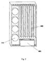
- Fig. 1 is a schematic view showing a non-closed type forced cooling frequency converter in the prior art.
- the conventional frequency converter of motor blows the cooling air to a heat sink 202 using a fan 201, and it also blows the cooling air to each elements in the circuit board simultaneously, resulting in the impurities in the air blown into the circuit board and contaminating internal devices, pins and pads, so that each elements in the circuit board has a potential risk to be short-circuit or damaged.
- the safety distance between respective elements in the circuit board depends on the contamination degree that the circuit board might suffer, i.e., the more contamination, the greater safety distance is required, which adversely affect the size reduction of the frequency converter.
- Fig. 2 is a schematic view showing a frequency converter in which main heat-generating element and a part of secondary heat-generating elements are forced cooled while the other secondary heat-generating elements are natural cooled.
- the conventional frequency converter of motor usually employs a combination cooling method of the fan forced cooling and the natural cooling through heat-dissipating holes, i.e. the power element such as the Insulating Gate Bipolar Transistor (IGBT) is forced cooled by the heat sink 202 and the fan 201, while the secondary heat-generating elements are natural cooled or a small amount of wind is blown to capacitors 111 and coils etc..
- the power element such as the Insulating Gate Bipolar Transistor (IGBT)
- the secondary heat-generating elements are natural cooled or a small amount of wind is blown to capacitors 111 and coils etc.
- aligning connection is performed between IGBT and the heat sink and between IGBT and the circuit board, which is generally achieved via aligning holes on the circuit board, the heat sink and IGBT.
- IGBT is usually adhered to the backboard of the heat sink by heat conductive silica gel, and then pressed on the circuit board.
- adhering IGBT on the heat sink may cause position deflection and rotation, thereby influencing the alignment between IGBT, the heat sink and the circuit board.
- each heat-generating elements of the frequency converter of motor is effectively heat-dissipated, and the heat-generating elements are heat insulated with other elements on the circuit board, so as to improve operation quality and lifetime of the product. Also, the problem of aligning positioning between IGBT and the heat sink and the circuit board need be solved.
- EP 0 356 991 A2 shows an inverter device comprising a circuit board having one first heat generating element (logical circuit section) mounted thereon. Second heat generating elements (main circuit section) are connected to the first heat generating element through a cable. Between the first heat generating element with the circuit board and the second heat generating element is arranged a separating member.
- the separating member comprises a heat sink for the first heat generating element.
- An air flow guiding member is placed between a fan and the heat sink for guiding cooling air from the fan to the heat sink and the second heat generating element respectively.
- US 2004/0061992 A1 shows an electronic device formed as a power control.
- Heat generating elements like a switching device, bus bars and connectors are mounted on a base of a heat sink.
- An air flow guiding member is arranged at the base for guiding cooling air from a fan to the heat sink and the heat generating elements.
- the base thereby serves as a separating member.
- the electronic device may further comprise a heat insulation member for thermally insulating said heat sink from said circuit board, wherein said heat insulation member is disposed in parallel with the backboard of said heat sink, and spaced in a predetermined distance, a heat insulation film comprising insulating materials is provide on a portion of backboard of said heat sink corresponding to said heat insulation member.
- the heat sink may further define a first airflow passage
- the separating member defines a second airflow passage in which said main body of said at least one second heat-generating element is resided, so that the cooling air guided to said at least one second heat-generating element flows along said second airflow passage, and cools said main body of said at least one second heat-generating element.
- said airflow guiding member and said second airflow passage may be configured as a streamline shape to eliminate vortex.
- said airflow guiding member, said separating member, said heat insulation member and said bracket may be integrally formed of the same insulating materials.
- a conductive member may be provided on said separating member to eliminate electromagnetic interference, wherein said conductive member may be formed of a metal material different from the material for the heat sink, or said conductive member may be formed of a conductive film layer formed on at least one portion of said separating member.
- said heat sink may be a fin-like shape, and comprises a plurality of fin plates substantially extending in parallel, so as to define a first airflow passage between each fin plates, said first airflow passage comprises an inlet end adjacent to said fan and an outlet end for guiding the airflow out of the electronic device.
- said heat sink may be provided with an inlet hole on the backboard of said inlet end, and an outlet hole on the backboard of said outlet end; alternatively the backboard of the inlet end of said heat sink could be spaced apart from said heat insulation member by a predetermined distance so as to form an inlet gap, and the backboard of the outlet end of said heat sink could be spaced apart from said heat insulation member by a predetermined distance so as to form a outlet gap, thereby cool the space between said heat sink and said heat insulation member.
- said fan may be spaced apart from said inlet end by a predetermined distance to reduce the wind resistance.
- the electronic device may further comprise a metal sheet matching with said separating member, which on one hand functions as an electromagnetic proof member, and on the other hand defines a second airflow passage together with the separating member, so as to position said main body of said at least one second heat-generating element in the second airflow passage, so that the cooling air guided to said at least one second heat-generating element flows along said airflow passage.
- the electronic device may further comprise a flow-guiding gate disposed between said fan and said heat sink for guiding the airflow from said fan to said heat sink, and dispensing more airflow to flow through a region corresponding to said at least first heat-generating element in said first airflow passage, so as to improve the heat dissipation effect of said heat sink.
- said electronic device may be a frequency converter for driving a motor
- said at least one first heat-generating element may comprise an insulating gate bipolar transistor, and may further comprise metal oxide semiconductor field effect transistor
- said at least one second heat-generating element may comprise at least one capacitor, and may comprise a coil.
- said heat sink may be formed by aluminum extrusion.
- FIG. 3 is a schematic view showing an electronic device according to the first embodiment of the present invention.
- at least one first heat-generating element 110 such as Insulating Gate Bipolar transistor (IGBT) module consisted of a plurality of IGBT and metal oxide semiconductor field effect transistor, are mounted on the circuit board 100.
- the IGBT module may have single IGBT or a plurality of IGBTs separately packaged, or may further comprise other functional elements, such as a metal oxide semiconductor field effect transistor etc.
- the at least one first heat-generating element 110 is connected to a heat sink 202 so as to be cooled.
- the heat sink 202 can be formed by aluminum extrusion or aluminum casting.
- Second heat-generating elements such as a plurality of capacitors 111a, 111b and a coil 112 shown in Fig. 3 , are mounted on the circuit board 100.
- the capacitors could be electrolytic capacitor with cylinder shape for example.
- a sub circuit board 101 may further be amounted on the circuit board 100, and the coil 112 may be amounted on the sub circuit board 101.
- the present invention is not limited thereto, and the coil 112 may also be amounted on the circuit board 100.
- a fan 201 is amounted on a side adjacent to the heat sink 202 to provide cooling air to the heat sink 202, so as to cool the IGBT module 110 connected to the heat sink 202.
- the electronic device of the present invention has airflow guiding members 211 a, 211 b and 211 c, through which the airflow from the fan 201 is blown to the heat sink 202, the capacitors 111 a, 111 b and the coil 112 respectively.
- IGBT module 110 is the main heat-generating element (hereafter called the first heat-generating element), while capacitors 111a, 111b and coil 112 are the secondary heat-generating elements (hereafter called the second heat-generating element), thereby the airflow guiding members 211a, 211 b and 211c dispenses most of the airflow to the heat sink 202, and dispenses the rest to the capacitors 111 a, 111 b and coil 112.
- the airflow dispensed to the heat sink 202 enters into the heat sink 202 from the inlet end 203a of the heat sink, and discharges out of the heat sink through the outlet end of the heat sink 202.
- the airflow dispensed to capacitors 111a, 111b and coil 112 flows to the capacitors 111a, 111b and coil 112 through the inlet hole 212a, and discharges out of the electronic device through the outlet hole 212b.
- the gap D there is a gap D between the fan 201 and the inlet end 203a of the heat sink 202, which can reduce the wind resistance of the airflow from the fan 201 effectively. Also, the gap D make it easier for the airflow guiding members 211 a, 211 b and 211 c to be disposed between the fan 201 and the inlet end 203a of the heat sink 202, and also allow the airflow guiding members 211 a, 211 b and 211 c to guide and dispense the airflow effectively.
- Fig. 4 is an exploded perspective view showing a frequency converter 200 according to the first embodiment
- Fig. 5 is an assembly view showing a frequency converter 200 according to the first embodiment.
- the frequency converter 200 will be described in details by referring to Fig 4 and Fig. 5 .
- the frequency converter 200 comprises: a fan 201 for supplying cool air to the frequency converter 200; a second airflow passage 210 for cooling the at least one second heat-generating element; a first airflow passage 240 for cooling the at least one first heat-generating element; and airflow guiding members 211 a, 211 b and 211 c placed between the fan 201 and the second airflow passage 210 and the first airflow passage 240 for dispensing the cooling air from the fan 201 to the second airflow passage 210 and the first airflow passage 240.
- the fan 201 has a box shape with a substantially square cross-section, and is detachably mounted on the case (not shown) of the frequency converter, so as to facilitate the replacement of the fan when it is required, thereby insuring the frequency converter being forced cooled effectively, and the lifetime of the fan can not influence the lifetime of the frequency converter, since replacing the fan is equivalent to extend the lifetime of the frequency converter accordingly.
- the air discharging capacity of the fan 201 may be larger than or not less than that needed to dissipate heat generated from the at least one first heat-generating element 110 and the at least one second heat-generating elements 111 a, 111 b and 112.
- the second airflow passage 210 is preferably formed of two portions.
- One is a lower body 220 formed of insulating materials, such as a polymer, which is a part of the separating member of a frequency converter for driving a motor so as to separate a main body of the second heat-generating element 111 a, 111 b and 112 or at least one part of it from said circuit board in a closed manner; and the other is an upper body 230 formed of, for example, a metal sheet, which also functions as a conductive member of the frequency converter for driving a motor so as to ground the frequency converter, thereby eliminating electromagnetic interference.
- the upper body 230 has a metal sheet with substantially “L"-shaped cross-section formed by pressing.
- a substantial box shape case is formed by assembling the upper body 230 having "L"-shaped cross-section with the lower body 220, and which are joined together by a connecting member, such as a clip and a buckle formed on the lower body 220 and the upper body 230 respectively.
- the inner surface of the second airflow passage 210 may be designed as a curve shape, such as streamline shape from the inlet hole 212a to the outlet hole 212b, so as to reduce airflow resistance to increase the efficiency of heat dissipation.
- an inlet hole 212a is formed on the side of the second airflow 210 corresponding to the outlet end of the secondary air passage 354.
- the airflow blown to the secondary air passage 354 by the fan 201 enters into the second airflow passage 210 through the inlet hole 212a.
- An outlet hole 212b is formed at the other end on the side of the second airflow passage 210 on which the inlet hole 212a is positioned.
- the outlet hole 212b gathers the airflow flowing through the second airflow passage 210 and the airflow flowing through the heat sink 202 together to discharge it to the outside through the outlet hole on the case.
- the outlet hole may also be disposed on the other side of the second airflow passage 210 to discharge the airflow flowing through the second airflow passage 210 and the airflow flowing through the heat sink 202 to the outside respectively.
- openings 221a and 230a, and 221b and 230b corresponding to each other are formed on the lower body 220 and the upper body 230 of the second airflow passage 210 at the position corresponding to the upper and lower plates of capacitors 111a and 111b, the shape and size of the openings 221 a and 230a, and 221 b and 230b correspond to the cross-section shape and size of the capacitors 111 a and 111 b, so that a part of the capacitors 111a and 111 b protrude into the second airflow passage through the openings 221a and 230a, and 221 b and 230b.
- the height of the part of the capacitors 111a and 111b protruding into the second airflow passage is preferably larger than or as least equal to 50% of the total height of the capacitors 111 a and 111 b.
- the height of the second airflow passage 210 is preferably larger than 50% of the height of the capacitors 111 a and 111 b, and the top surface of the second airflow passage 210 and the top surface of the capacitors 111 a and 111b are disposed at the same level, in order to insure more than 50% of the side surface of the capacitors positioned in the effective cooling region of the second airflow 210.
- a sealing process such as using a seal gasket, can be carried out between the lower body 220 and the capacitors 111a and 111b, in order to prevent impurities in the second airflow passage 210 from flowing in the circuit board on which the capacitors 111a and 111b are mounted, thereby preventing the other elements on the circuit board from being contaminated or damaged.
- the capacitors 111a and 111b protrude through the openings 230a and 230b to a level at which the top surface of the upper body 230 is positioned, and are fixed on the top surface of the upper body 230 by insulating adhesive, such as epoxy resin, to prevent short circuit between The capacitors 111a and 111b and the top surface.
- the capacitors 111a and 111b may not protrude to the top surface of the upper body 230, in this case, the part protruding above the lower body 220 is completely accommodated in the second airflow passage 210, and it is not necessary to dispose openings on the upper body 230 at the position corresponding to the capacitors 111a and 111b.
- a good heat dissipating effect can be achieved even when only the top surface of the capacitors can protrude into the second airflow passage 210.
- an opening 222 is formed on the sidewall of the second airflow passage 210 at the position corresponding to the coil 112.
- the coil 112 is accommodated in a coil cover 375, and is mechanically/electrically connected to the circuit board with the coil cover 375 serving as an insulating layer therebetween.
- the coil cover 375 has a sidewall, so as to form a coil cover with one opening end. Because the shape and size of the opening 222 can correspond to the shape and size of the opening end of the coil cover 375, the inner space of the coil cover 375 becomes a part of the second airflow passage 210 after the coil cover 375 is air-tightly connected to the opening 222 of the second airflow passage 210.
- the heat generated from the coil 112 is exchanged with the airflow flowing in the second airflow passage 210 through the opening 222, and discharges to the outside through an outlet 212b.
- the present invention is not limited thereto, for example, the coil 112 can protrude into the second airflow passage 210 from the sub circuit board 101, so as to eliminating the pieces such as the coil cover 375.
- the coil 112 may also be disposed on the circuit board 100, and protrudes into the second airflow passage 210 through the opening on the lower body 220 at the position corresponding to the coil 112.
- a plurality of side arms 223a extending from the upper body 230 of the second airflow passage 210 formed of a metal at a proper position, as a conductive member of the frequency converter, is electrically connected with the heat sink 202 and a plurality of ground ends of the circuit board to achieve the grounding of the whole frequency converter to eliminate electromagnetic interference.
- a plurality of side arms 223b are formed on the lower body 220 of the second airflow passage 210 formed of a polymer, and they correspond to the plurality of side arms 223a on the upper body 230 of the second airflow passage 210 formed of a metal. After the lower body and the upper body 220 and 230 are assembled together, the side arms 223a and 223b are bonded to each other to increase the mechanical strength of the plurality of the side arms for grounding.
- an airflow guiding member 211 is disposed adjacent to the outlet of the fan 201.
- the airflow guiding member 211 comprises side airflow guiding members 211 a and 211c and a main airflow guiding member 211b.
- An inlet of a substantial trapezoid airflow passage surrounded by the side airflow guiding members 211 a and 211 c corresponds to the outlet of the fan 201
- an outlet of a main airflow passage 355 surrounded by the side guiding member 211 a and the main airflow guiding member 211 b corresponds to the inlet of the heat sink 202
- an outlet of a secondary airflow passage 354 surrounded by the side airflow guiding member 211c and the main airflow guiding member 211b corresponds to the inlet hole 212a of the second airflow passage 210.
- the airflow guiding member 211a, 211b and 211c at least has the following effects: forming the main airflow passage 355 from the fan 201 to the heat sink 202; forming the secondary airflow passage 354 from the fan 201 to The second airflow passage 210; forming a streamline smoothing surfaces of the main airflow passage 355 and the secondary airflow passage 354 with different sizes, in order to reduce powder consumption due to air vortex.
- the position and angle of the main airflow guiding member 211b being disposed directly influent an amount of the airflow dispensed to the main airflow passage 355 and the secondary airflow passage 354 and the direction of the airflow flowing in the secondary airflow passage 354.
- the inlet of the main airflow guiding member 211 b is disposed to closely contact with the outlet of the fan 201, and a contact line (or stripe-like plane) thereof divides the outlet of the fan 201 into a region corresponding to the main airflow passage 355 and a region corresponding to the secondary airflow passage 354, and the area ratio of the region corresponding to the main airflow passage 355 to the region corresponding to the secondary airflow passage 354 is substantially equal to the air throughput ratio of the main airflow passage 355 to the secondary airflow passage 354.
- the outlet end of the main airflow guiding member 211b is disposed to correspond to an end surface of a side fin of the heat sink 202 adjacent to at least one second heat-generating element, and the secondary airflow passage 354 substantially corresponds to the at least one second heat-generating element 111a and 111b.
- the main airflow guiding member 211b is formed with a streamline cross-section, and its two side surfaces are fluid-like smoothing surface.
- the main airflow guiding member 211 b and the side airflow guiding members 211 a and 211 c are integrally formed of a polymer.
- the airflow guiding members 211 a, 211 b and 211 c and the lower body 220 of the second airflow passage 210 may integrally be ;forme of the same materials.
- the airflow guiding members 211a, 211b and 211c may also be formed separately, or the main airflow guiding member 211b in the airflow guiding members 211a, 211b and 211 c may be formed separately and then is adhered to the side airflow guiding members 211 a and 211 c or an end face of a side wall of the heat sink 202 by such as adhesive.
- the first airflow passage 240 is a closed airflow passage formed by the heat sink 202 and the case (not shown).
- the heat sink 240 may be fin-shaped formed by aluminum extrusion or aluminum casting. However, the present invention is not limited thereto, for example, the heat sink may be formed into any kind of shapes adapted to form an airflow passage for forced cooling.
- the heat sink comprises a plurality of fin plates extending substantially in parallel with each other , so as to define the first airflow passage 240 between each fin plates.
- the first airflow passage 240 comprises an inlet end 203a adjacent to the fan and an outlet end 203b for guiding the airflow out of the electronic device.
- the at least one first heat-generating element of the frequency converter such as an IGBT model, is disposed to contact the backboard of the heat sink 202 tightly by such as heat conductive silica gel, so that the heat from the at least one first heat-generating element may be insured to be dissipated by the heat sink 202 under forced cooling of the fan 201.
- the second embodiment not according to the present invention but useful for illustrative purposes has substantially the same structure as that of the first embodiment except the separating member 220 and the conductive member 230. Therefore, the separating member 220 and the conductive member 230 of the second embodiment will mostly be described hereafter, and thereby omitting the same description with the first embodiment.
- Fig. 6 is a schematic view showing an electronic device according to the second embodiment.
- the separating member 220 is formed with a rectangle box shape, which is substantially the same as that of the second airflow passage of the first embodiment. Therefore, the separating member 220 has two functions: one is to separate a main body of the at least one second heat-generating element on the circuit boards 100 and 101 or at least one portion of the main body from the other elements on the circuit board; the other is to define a second airflow passage of the electronic device, instead of defining the second airflow passage by both the separating member 220 and the conductive member 230 in the first embodiment, so that at least one second heat-generating member, such as capacitors 111a and 111b and coil 112, in the electronic device or at least a portion thereof protrude into the second airflow passage.
- at least one second heat-generating member such as capacitors 111a and 111b and coil 112
- the purpose for cooling the at least one second heat-generating element is achieved while insuring that the cooling air can not enter into the circuit boards 100 and 101, thereby preventing the impurities in the cooling air from contaminating the other elements on the circuit boards 100 and 101 and short circuit malfunction therefrom.
- the conductive member 230 may be formed of a metal sheet on the separating member 220 with a shape adapted to ground the frequency converter.
- the conductive member 230 may be formed, for example, by coating a metal film on at least one part of the separating member 220.
- the third embodiment which is according to the present invention has the same structure as that of the first embodiment and the second embodiment except the bracket of the at least one first heat generating element and the separating member. Therefore, the bracket of the third embodiment will be described hereafter, and thereby omitting the same description with the first embodiment and the second embodiment.
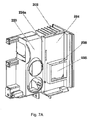
- Fig. 7A is a bottom view of the bracket 226 and the heat insulation member 224 of the frequency converter according to the third embodiment of the present invention
- Fig. 7B is a top view of the bracket 226 and the heat insulation member 224 of the frequency converter according to the third embodiment of the present invention.
- the heat insulation member 224 may integrally be formed with the separating member 220, i.e. the separating member 220 may be bent downward and extends on a side of the heat sink 202 to form a sidewall 224a of the heat insulation member 224 and then continuously extends horizontally.
- the heat insulation member 224 is disposed between the heat sink 202 and circuit board 100 to form heat insulation between the heat sink 202 and circuit 100, so as to prevent the heat of the heat sink 202 from transferring to circuit board 100, thereby further protecting the circuit board 100.
- an opening 225 is formed in the heat insulation member 224 at a position corresponding to the at least one first heat-generating element 110, such as IGBT.
- the shape of the opening 225 corresponds to the shape of the at least one heat-generating element 110 with cross-section area of the opening slightly larger than that of the at least one heat-generating element 110, so that the at least one heat-generating element 110 make contact with the heat sink 202 through the opening.
- a bracket 226 is formed around the opening 225, protruding down from the heat insulation member 224 by a height which is equal to the thickness of the at least one first heat-generating element 100.
- the bracket 226 has a square cross-section corresponding to the at least one first heat-generating element 110, however, the present invention is not limited thereto, which can have a cross-section with a shape such as circle or polygon.
- the bracket 226 is bonded to the backboard of the heat sink 202 to define the mounting position of the at least one first heat-generating element 110, which is instrumental in the positioning of the at least one first heat-generating element 110 during the assembly process.
- bracket 226 thermally insulates the first heat-generating element 110, such as IGBT model, from the other elements on the circuit board 100, in particular heat sensitivity elements, so as further to protect the other elements on the circuit board around the first heat-generating element 110.
- the disposition of bracket 226 can also prevent the influence to the other elements around the first heat-generating element 110 even if the first heat-generating element 110 is shorted or exploded.
- the bracket 226 may also formed in an incomplete isolating form, depending on different structure of the circuit board 100, i.e. sidewalls of the bracket 226 may be provided at the sides corresponding to the heat sensitivity elements while sidewall of the bracket 226 is not provided at the other sides.
- the bracket 226 may be formed separately or may integrally be formed with the heat insulation member 224, even may integrally formed with the bracket 226, the heat insulation member 224 and the separating member 220, depending on the practical needs of the heat insulation of the electronic device.
- bracket 226 is formed without the heat insulation member 224.
- the bracket 226 may be formed separately or may integrally be formed with the separating member 220.
- the bracket 226 may comprise sidewall pates around the IGBT model 100 to have functions as follows: thermally insulating from the other elements therearound; positioning of the IGBT model; preventing the other elements from damage duet to the explosion of IGBT model.
- only the heat insulation member 224 is formed without the bracket 226.
- the heat insulation member 224 has a structure which extends in parallel with the backboard of the heat sink 202, and an opening is disposed at the position corresponding to the IGBT model 110, so that the IGBT model 110 makes thermal contact with the heat sink 202 through the opening.
- the fourth embodiment also according to the present invention has the same structure as that of the third embodiment except the arrangement of the heat insulation member 224. Therefore, the arrangement of the heat insulation member 224 and the associated structural change thereof of the fourth embodiment will be described hereafter, and thereby omitting the same description as the third embodiment.
- Fig. 8A is an exploded perspective view illustrating the relationship between the heat sink 202 and the heat insulation member 224 of the frequency converter according to the fourth embodiment of the present invention
- Fig. 8B is a side view of the frequency converter according to the fourth embodiment of the present invention.
- the heat sink 202 and the heat insulation member 224 are disposed substantially in parallel with each other with a predetermine distance therebetween. Therefore, a space is defined between the backboard of the heat sink 202 and the heat insulation member 224.
- the space is an excellent heat insulation layer, i.e. another heat insulation layer is formed between the heat sink 202 and circuit board 100, so as to prevent the heat of the heat sink from transferring to the elements sensitive to heat on the circuit board 100, and thereby protecting the circuit board 100.
- the heat-insulation effect of the space can not eventually be obtained unless heat is exchanged between the air in the space and the air out of the frequency converter in time.
- the heat sink 202 has an inlet hole 204a at the inlet end 203a and an outlet hole 204b at the outlet end 203b.
- the airflow from the fan 201 is partially introduced into the heat-insulation space through the inlet hole 204a, and then is discharged out of the frequency converter through the outlet hole 204b. after heat exchange therein, thereby an airflow passage is formed by the inlet hole 204a, the space between the heat sink 202 and the heat insulation member, and the outlet hole 204b.
- the inlet hole 204a and the outlet hole 204b can be replaced respectively by a gap formed between the backboard of the heat sink 202 at the inlet end 203a and the heat insulation member 224 and a gap formed between the backboard of the heat sink 202 at the outlet end 203b and the heat insulation member 224. That is, the present invention do not limit the structure of the above mentioned inlet hole 204a and outlet hole 204b, as long as they can functions as an air inlet and an air outlet respectively.
- a heat insulation film (not shown) is disposed on the backboard of the heat sink 202 at the position corresponding to the heat insulation member 224, thereby further reducing the heat transferring from the heat sink 202 to circuit board 100.
- the heat insulation film comprises insulating materials for example.
- the fifth embodiment also according to the present invention has the same structure as that of the first to fourth embodiments except adding a flow-guiding gate. Therefore, the flow-guiding gate of the fifth embodiment will mostly be described hereafter, and thereby omitting the same description with the first to fourth embodiment.
- Fig. 9 is a side view of the structure of the frequency converter with flow-guiding gate according to the fifth embodiment of the present invention.
- the flow-guiding gate 250 is provided between the fan 201 and the heat sink 202.
- the flow-guiding gate 250 comprises a gate plate disposed thereon for guiding the airflow from the fan 201 to the heat sink 202.
- the direction of the airflow through the gate plate can be adjusted by changing the angle of the gate plate, and thereby dispensing more airflow flowing through a heat concentration region in the first airflow passage, i.e. a region corresponding to IGBT model.
- the flow-guiding gate 250 may be made of insulating materials, and is preferably made of the same materials as that of the airflow guiding members 211 a, 211 b and 211 c, and further preferably is integrally formed of the same materials as the airflow guiding member 211 a, 211 b and 211 c.
- the flow-guiding gate 250 may be disposed between the fins of the heat sink 202 between the fan 201 and the IGBT model, and an insertion-type flow-guiding gate is plugged into the space between the fins of the heat sink 202, so that the airflow flowing through the flow-guiding plates correspond to the position of the IGBT model located.
- the sixth embodiment also according to the present invention has main features as those of the first to fifth embodiments. Therefore, the combination of these main features will be described hereafter, and thereby omitting the description to the other parts.
- Fig. 10A is an exploded perspective view of the structure of the frequency converter with the airflow guiding member 211, the separating member 220, the heat insulation member 224, bracket 226 and flow-guiding gate 250 according to the sixth embodiment of the present invention
- Fig. 10B is an upside-down rear exploded perspective view of Fig. 10A .
- the frequency converter according to the sixth embodiment of the present invention comprises: a circuit board 100, which has a IGBT model 110 as a main heat-generating element and a capacitor 111 as a secondary heat-generating element; sub circuit board 101, which has a coil 112 as another secondary heat-generating element, and the sub circuit board 101 and the circuit board 100 are disposed as substantially perpendicular to each other; a heat sink 202, which is disposed on the IGBT model 110; a fan 201, which is disposed on the case (not shown) of the frequency converter corresponding to the inlet end of the heat sink 202; an airflow guiding member 211, a separating member 220, a heat insulation member 224 and a bracket 226, which may integrally formed of the same insulating materials by injection molding for example; and flow-guiding gate 250, which guides more airflow from the fan 201 to a region of the heat sink corresponding to the IGBT model.
- the airflow-guiding member 211 is disposed between the fan 201 and the heat sink 202 at the side adjacent to the capacitor 111, and dispenses the airflow from the fan 201 to the heat sink 202 and the capacitor 111 and the coil 112 respectively;
- the separating member 220 is disposed over the circuit board 100 for separating the main body of the capacitor 111 from the other elements on the circuit board;
- the heat insulation member 224 is disposed between the circuit board 100 and heat sink 202 to thermally insulate the circuit board 100 and the heat sink 202;
- the bracket 226 is disposed between the circuit board 100 and the heat sink 202 at the position corresponding to the IGBT model 110, for defining a mounting position of the IGBT model, thus thermally insulate the IGBT and the other elements on the circuit board 100, and preventing the other elements on the circuit board from damage due to the explosion of the IGBT 110.
- the frequency converter of the present embodiment further comprises a conductive member 230 formed of metal materials, which is jointed with the separating member 220 to form a closed second airflow passage as described above, and the conductive member 230 further serves as a ground member of the frequency converter to eliminate electromagnetic interference.
- the frequency converter further comprises a coil cover 375 accommodating the coil 112 is fixed on the sub circuit board 101 for separating the sub circuit board 101 and the coil 112.
- the coil cover 375 is connected to the second airflow passage describe above to become a part of the second airflow passage, so that the coil 112 is positioned in the second airflow passage to be cooled.
- a heat insulation film (not shown) is disposed on the backboard of the heat sink 202 at the position corresponding to the heat insulation member 224, with a predetermined distance between the heat sink 202 and the heat insulation member 224.
- An inlet hole 204a and an outlet hole 204b are disposed at the both ends of the heat sink respectively.
- the airflow from the fan 201 is introduced into the space between the heat sink 202 and the heat insulation member 224 through the inlet hole 204a, and discharged out of the frequency converter through the outlet hole 204b.
- a cooling airflow passage is formed in the space between the heat sink 202 and the heat insulation member 224, to prevent the heat of the heat sink from transferring to the circuit board.
- the separating member and cooling device of the frequency converter according to the present invention may adapt not only to the frequency converter but also to any electronic device with two or more heat-generating elements.
Landscapes
- Engineering & Computer Science (AREA)
- Microelectronics & Electronic Packaging (AREA)
- Physics & Mathematics (AREA)
- Thermal Sciences (AREA)
- Cooling Or The Like Of Electrical Apparatus (AREA)
- Cooling Or The Like Of Semiconductors Or Solid State Devices (AREA)
Claims (14)
- Dispositif électronique, comportant:une carte (100) à circuits sur laquelle sont montés au moins un premier élément (110) générateur de chaleur et au moins un deuxième élément (111a, 111b, 112) générateur de chaleur;un dissipateur thermique (202) relié audit ou auxdits premiers éléments (110) générateurs de chaleur; etun ventilateur (201) faisant face au dissipateur thermique (202),le dispositif électronique comportant en outre un organe (211a, 211b, 211c) de guidage d'écoulement d'air placé entre le ventilateur (201) et le dissipateur thermique (202) pour guider l'air de refroidissement en provenance du ventilateur (201) respectivement vers le dissipateur thermique (202) et le ou les deuxièmes éléments (111a, 111b, 112) générateurs de chaleur, comportant en outre un organe séparateur (220) servant à séparer un corps principal du ou des deuxièmes éléments (111a, 111b, 112) générateurs de chaleur par rapport à la carte (100) à circuits, de façon à empêcher l'air de refroidissement guidé vers le ou les deuxièmes éléments (111a, 111b, 112) générateurs de chaleur de s'écouler vers la carte (100) à circuits, caractérisé en ce que le dispositif électronique comporte en outre une monture (226) du ou des premiers éléments (110) générateurs de chaleur, en ce que la monture comporte des parois latérales et isole thermiquement le premier élément (110) générateur de chaleur par rapport à d'autres éléments sur la carte (100) à circuits.
- Dispositif électronique selon la revendication 1, le dissipateur thermique (202) étant formé par extrusion d'aluminium.
- Dispositif électronique selon la revendication 1, ledit organe séparateur (220) étant formé de matériaux isolants et l'organe (211a, 211b, 211c) de guidage d'écoulement d'air et l'organe séparateur (220) étant de préférence formés d'un seul tenant des mêmes matériaux isolants.
- Dispositif électronique selon la revendication 1, comportant en outre un organe (224) d'isolation thermique servant à isoler thermiquement le dissipateur thermique (202) par rapport à la carte (100) à circuits, qui est disposé parallèlement au panneau-support du dissipateur thermique (202) et espacé d'une distance prédéterminée, le panneau-support du dissipateur thermique (202) étant de préférence muni d'un film d'isolation thermique sur la surface correspondant à l'organe (224) d'isolation thermique, ledit film d'isolation thermique comportant de préférence des matériaux isolants.
- Dispositif électronique selon la revendication 1, le dissipateur thermique (202) définissant un premier passage (240) d'écoulement d'air, et l'organe séparateur (220) définissant un deuxième passage (210) d'écoulement d'air dans lequel est positionné le corps principal du ou des deuxièmes éléments (111a, 111b, 112) générateurs de chaleur, de telle sorte que l'air de refroidissement guidé vers le ou les deuxièmes éléments (111a, 111b, 112) générateurs de chaleur s'écoule le long du deuxième passage (210) d'écoulement d'air et refroidit le corps principal du ou des deuxièmes éléments (111a, 111b, 112) générateurs de chaleur, le deuxième passage (210) d'écoulement d'air présentant de préférence un trou (212a) d'entrée adjacent à l'organe (211a, 211b, 211c) de guidage d'écoulement d'air et un trou (212b) de sortie servant à guider l'écoulement d'air hors du dispositif électronique.
- Dispositif électronique selon la revendication 1, l'organe (211a, 211b, 211c) de guidage d'écoulement d'air et le deuxième passage (210) d'écoulement d'air étant configurés sous une forme profilée pour éliminer les tourbillons.
- Dispositif électronique selon la revendication 1, l'organe (211a, 211b, 211c) de guidage d'écoulement d'air, l'organe séparateur (220), l'organe (224) d'isolation thermique et la monture (226) étant formés d'un seul tenant des mêmes matériaux isolants.
- Dispositif électronique selon la revendication 1, un organe conducteur (230) étant mis en place sur l'organe séparateur (220) pour éliminer le brouillage électromagnétique, qui est de préférence formé d'un matériau métallique différent du matériau du dissipateur thermique (202) et de façon plus préférable formé d'une couche de film conducteur formée sur au moins une partie de l'organe séparateur (220).
- Dispositif électronique selon la revendication 1, le dissipateur thermique (202) présentant une forme en ailettes et comportant une pluralité de plaques d'ailettes s'étendant sensiblement en parallèle pour définir un premier passage (240) d'écoulement d'air entre chacune des plaques d'ailettes, le premier passage (240) d'écoulement d'air comportant une extrémité (203a) d'entrée adjacente au ventilateur et une extrémité (203b) de sortie servant à guider l'écoulement d'air hors du dispositif électronique, le ventilateur (201) étant de préférence espacé d'une distance prédéterminée par rapport à l'extrémité (203a) d'entrée pour réduire la résistance aérodynamique.
- Dispositif électronique selon la revendication 4, le dissipateur thermique (202) étant muni d'un trou (204a) d'entrée sur le panneau-support de l'extrémité (203a) d'entrée, et d'un trou (204b) de sortie sur le panneau-support de l'extrémité (203b) de sortie, de façon à former un passage d'écoulement d'air dans l'espace compris entre le dissipateur thermique (202) et l'organe (224) d'isolation thermique.
- Dispositif électronique selon la revendication 4, un interstice d'entrée étant disposé entre le panneau-support de l'extrémité (203a) d'entrée du dissipateur thermique (202) et l'organe (224) d'isolation thermique, et un interstice de sortie étant disposé entre le panneau-support de l'extrémité (203b) de sortie et l'organe (224) d'isolation thermique, de façon à former un passage d'écoulement d'air dans l'espace compris entre le dissipateur thermique (202) et l'organe (224) d'isolation thermique.
- Dispositif électronique selon la revendication 1, comportant en outre une feuille métallique s'adaptant à l'organe séparateur (220), qui d'une part fait fonction d'organe de protection électromagnétique et d'autre part définit un deuxième passage (210) d'écoulement d'air conjointement avec l'organe séparateur (220), de façon à positionner le corps principal du ou des deuxièmes éléments (111a, 111b, 112) générateurs de chaleur dans le deuxième passage (210) d'écoulement d'air, de telle sorte que l'air de refroidissement guidé vers le ou les deuxièmes éléments (111a, 111b, 112) générateurs de chaleur s'écoule à travers le passage d'écoulement d'air, le deuxième passage (210) d'écoulement d'air présentant un trou (212a) d'entrée adjacent à l'organe (211a, 211b, 211c) de guidage d'écoulement d'air et un trou (212b) de sortie servant à guider l'écoulement d'air hors du dispositif électronique.
- Dispositif électronique selon la revendication 1, comportant en outre une grille (250) de guidage d'écoulement disposée entre le ventilateur (201) et le dissipateur thermique (202), guidant l'écoulement d'air en provenance du ventilateur (201) vers le dissipateur thermique (202), et distribuant un débit d'air plus important appelé à s'écouler à travers une région du premier passage (240) d'écoulement d'air correspondant audit ou auxdits premiers éléments (110) générateurs de chaleur.
- Dispositif électronique selon l'une quelconque des revendications 1 à 12, le dispositif électronique étant un convertisseur de fréquence servant à commander un moteur, le ou les premiers éléments (110) générateurs de chaleur comportant au moins un transistor bipolaire à grille isolée, et le ou les deuxièmes éléments (111a, 111b, 112) générateurs de chaleur comportant au moins un condensateur (111), le ou les premiers éléments (110) générateurs de chaleur comportant en outre de préférence un transistor à effet de champ à semiconducteur à oxyde métallique; et le ou les deuxièmes éléments générateurs de chaleur comportant en outre une bobine (112).
Applications Claiming Priority (2)
| Application Number | Priority Date | Filing Date | Title |
|---|---|---|---|
| CNA2006101659416A CN101202529A (zh) | 2006-12-11 | 2006-12-11 | 电子装置及电动机变频器 |
| PCT/DK2007/000539 WO2008071190A1 (fr) | 2006-12-11 | 2007-12-10 | Dispositif électronique et convertisseur de fréquence de moteur |
Publications (2)
| Publication Number | Publication Date |
|---|---|
| EP2090146A1 EP2090146A1 (fr) | 2009-08-19 |
| EP2090146B1 true EP2090146B1 (fr) | 2014-07-09 |
Family
ID=39323812
Family Applications (1)
| Application Number | Title | Priority Date | Filing Date |
|---|---|---|---|
| EP07846409.6A Active EP2090146B1 (fr) | 2006-12-11 | 2007-12-10 | Dispositif électronique et convertisseur de fréquence de moteur |
Country Status (4)
| Country | Link |
|---|---|
| US (1) | US8363408B2 (fr) |
| EP (1) | EP2090146B1 (fr) |
| CN (1) | CN101202529A (fr) |
| WO (1) | WO2008071190A1 (fr) |
Cited By (2)
| Publication number | Priority date | Publication date | Assignee | Title |
|---|---|---|---|---|
| DE102017214779A1 (de) | 2017-08-23 | 2019-04-04 | Lenze Automation Gmbh | Elektrisches Steuergerät |
| EP3251882B1 (fr) | 2016-05-30 | 2019-04-17 | Magneti Marelli S.p.A. | Machine électrique présentant une architecture tangentielle ayant un refroidissement par air amélioré |
Families Citing this family (48)
| Publication number | Priority date | Publication date | Assignee | Title |
|---|---|---|---|---|
| FI20095436A7 (fi) * | 2009-04-21 | 2010-10-22 | Abb Oy | Sähkökäyttö |
| WO2011068151A1 (fr) * | 2009-12-04 | 2011-06-09 | 三洋電機株式会社 | Unité d'accumulation d'électricité et système de production d'énergie |
| JP5344182B2 (ja) * | 2010-02-02 | 2013-11-20 | 株式会社安川電機 | 電力変換装置 |
| KR20120055307A (ko) * | 2010-11-23 | 2012-05-31 | 삼성전기주식회사 | 방열기판 및 그 제조방법 |
| DE102012014011A1 (de) | 2011-08-02 | 2013-02-07 | Sew-Eurodrive Gmbh & Co. Kg | Elektrogerät |
| TW201323817A (zh) * | 2011-12-13 | 2013-06-16 | 鴻海精密工業股份有限公司 | 散熱器 |
| US9530714B2 (en) * | 2012-12-13 | 2016-12-27 | Nvidia Corporation | Low-profile chip package with modified heat spreader |
| JP5657716B2 (ja) * | 2013-01-15 | 2015-01-21 | ファナック株式会社 | 放熱器を備えたモータ駆動装置 |
| EP2879476B1 (fr) * | 2013-11-29 | 2016-06-29 | ABB Technology Oy | Appareil électrique |
| US9825437B2 (en) * | 2014-06-04 | 2017-11-21 | Hamilton Sundstrand Corporation | Three-dimensional power distribution interconnect structure |
| JP6559771B2 (ja) | 2014-09-16 | 2019-08-14 | エスゼット ディージェイアイ テクノロジー カンパニー リミテッドSz Dji Technology Co.,Ltd | 放熱装置及びこの放熱装置を用いるuav |
| DE102015202197A1 (de) * | 2015-02-06 | 2016-08-11 | Schmidhauser Ag | Frequenzumrichter und Verfahren zur Herstellung eines Frequenzumrichters |
| WO2016139763A1 (fr) * | 2015-03-04 | 2016-09-09 | 株式会社日立製作所 | Unité et dispositif de conversion d'énergie électrique |
| CN106332507B (zh) * | 2015-06-15 | 2019-04-02 | 上海三菱电梯有限公司 | 功率器件散热装置 |
| EP3365915B1 (fr) * | 2016-02-16 | 2025-06-11 | Siemens Aktiengesellschaft | Radiateur et dispositif électrique |
| JP2016166000A (ja) * | 2016-04-06 | 2016-09-15 | 株式会社東芝 | 車両用電力変換装置 |
| WO2017218614A1 (fr) | 2016-06-15 | 2017-12-21 | Hunter Fan Company | Système de ventilateur de plafond et boîtier de composants électroniques |
| CN107924746B (zh) * | 2016-06-16 | 2019-06-04 | 富士电机株式会社 | 电子设备和电力变换装置 |
| DE102016221404A1 (de) * | 2016-10-31 | 2018-05-03 | Siemens Aktiengesellschaft | Luftkühlung eines Wechselrichters |
| CN106602884B (zh) * | 2016-12-13 | 2023-06-09 | 华远电气股份有限公司 | 一种独立风道结构的变频器及其装配工艺 |
| KR102378474B1 (ko) * | 2017-08-09 | 2022-03-25 | 엘지전자 주식회사 | 의류처리장치 |
| EP3490351B1 (fr) * | 2017-11-24 | 2020-11-11 | Siemens Aktiengesellschaft | Appareil de commutation basse tension doté d'un dispositif de refroidissement défini |
| EP3490353A1 (fr) * | 2017-11-27 | 2019-05-29 | Siemens Aktiengesellschaft | Système de refroidissement à canaux de refroidissement parallèles |
| DE112018006234T5 (de) * | 2017-12-07 | 2020-09-17 | Mitsubishi Electric Corporation | Halbleitereinheit |
| CN208227548U (zh) * | 2018-04-18 | 2018-12-11 | 哈曼国际工业有限公司 | 电子装置和用于电子装置的散热装置 |
| CN110932526A (zh) * | 2018-09-18 | 2020-03-27 | 致茂电子(苏州)有限公司 | 电源供应装置 |
| WO2020118629A1 (fr) * | 2018-12-13 | 2020-06-18 | 深圳市大疆创新科技有限公司 | Dispositif électronique |
| IT201800020599A1 (it) * | 2018-12-20 | 2020-06-20 | Eldor Corp Spa | Elemento di connessione per un inverter ed inverter comprendente detto elemento di connessione |
| CN119095336A (zh) * | 2019-01-18 | 2024-12-06 | 比泽尔电子股份公司 | 电子功率设备和冷却回路 |
| CN109768739B (zh) * | 2019-01-30 | 2020-10-30 | 江苏博德纳系统工程股份有限公司 | 一种电机调速控制器及其控制系统 |
| USD944204S1 (en) | 2019-07-01 | 2022-02-22 | Nidec Motor Corporation | Motor controller housing |
| USD920914S1 (en) | 2019-07-01 | 2021-06-01 | Nidec Motor Corporation | Motor air scoop |
| EP4307850B1 (fr) * | 2019-11-18 | 2026-01-14 | Huawei Digital Power Technologies Co., Ltd. | Composant électronique avec cadre de boîtier, carte de circuit imprimé avec composant électronique et dispositif électronique |
| CN110912378B (zh) * | 2019-12-03 | 2022-10-04 | 西安中车永电电气有限公司 | 一种基于电气隔离悬挂框架的内燃机车嵌套式热管散热器 |
| CN113038776B (zh) * | 2019-12-24 | 2025-01-24 | 中科寒武纪科技股份有限公司 | 用于电子设备的机架及使用该机架的电子设备 |
| CN113133261B (zh) * | 2019-12-30 | 2022-07-22 | 华为数字能源技术有限公司 | 一种散热装置、电路板组件及电子设备 |
| CN112004387B (zh) * | 2020-09-10 | 2022-09-06 | 科华恒盛股份有限公司 | 一种模块散热结构 |
| CN112311206B (zh) * | 2020-11-12 | 2022-04-26 | 苏州汇川技术有限公司 | 换热系统及变频器 |
| CN113056179B (zh) * | 2021-03-31 | 2023-05-02 | 联想(北京)有限公司 | 一种电子设备 |
| JP7611051B2 (ja) | 2021-03-31 | 2025-01-09 | ニデックインスツルメンツ株式会社 | モータ制御装置 |
| CN113851973B (zh) * | 2021-09-08 | 2024-11-08 | 上海卡邦电气东台有限公司 | 便于变频器散热的控制机柜 |
| CN116266982B (zh) * | 2021-12-16 | 2026-03-20 | 台达电子企业管理(上海)有限公司 | 电源装置 |
| CN115103578B (zh) * | 2022-07-27 | 2022-11-11 | 深圳市德兰明海科技有限公司 | 一种外置内循环风道组件以及应用该组件的逆变器 |
| CN114980709B (zh) * | 2022-07-28 | 2022-09-30 | 深圳市德兰明海科技有限公司 | 一种双风道散热组件以及应用该组件的逆变器 |
| CN115665970B (zh) * | 2022-10-08 | 2023-11-21 | 江苏东海半导体股份有限公司 | 一种igbt驱动保护电路板 |
| US20240247787A1 (en) * | 2023-01-23 | 2024-07-25 | Musco Corporation | Extended knuckle, snout, and aiming device for retrofitting a lighting system with led lights |
| CN119383933B (zh) * | 2024-12-30 | 2025-04-25 | 乐山希尔电子股份有限公司 | 一种逆变电源及供电方法 |
| CN119403100B (zh) * | 2024-12-31 | 2025-04-18 | 深圳科士达科技股份有限公司 | 充电模块 |
Family Cites Families (28)
| Publication number | Priority date | Publication date | Assignee | Title |
|---|---|---|---|---|
| KR920005988B1 (ko) * | 1988-08-31 | 1992-07-25 | 가부시기가이샤 히다찌세이사꾸쇼 | 인버터장치 |
| DE9320825U1 (de) | 1993-11-26 | 1995-02-23 | Siemens AG, 80333 München | Gehäuse |
| EP0655881A1 (fr) * | 1993-11-26 | 1995-05-31 | Siemens Aktiengesellschaft | Boîtier |
| US5694294A (en) * | 1995-01-27 | 1997-12-02 | Hitachi, Ltd. | Portable computer with fan moving air from a first space created between a keyboard and a first circuit board and a second space created between the first circuit board and a second circuit board |
| US5793608A (en) * | 1996-06-11 | 1998-08-11 | Sun Microsystems, Inc. | Cooling system for enclosed electronic components |
| US5757638A (en) * | 1996-12-31 | 1998-05-26 | Sansha Electric Manufacturing Company, Limited | Power supply apparatus |
| DE19813639A1 (de) * | 1998-03-27 | 1999-11-25 | Danfoss As | Leistungsmodul für einen Stromrichter |
| JPH11299285A (ja) * | 1998-04-16 | 1999-10-29 | Fanuc Ltd | サーボアンプ |
| DE19983152T1 (de) * | 1999-02-24 | 2001-05-31 | Mitsubishi Electric Corp | Leistungstreibervorrichtung |
| DE60137843D1 (de) * | 2000-06-06 | 2009-04-16 | Panasonic Corp | Tragbares informationsgerät |
| DE10058574B4 (de) * | 2000-11-24 | 2005-09-15 | Danfoss Drives A/S | Kühlgerät für Leistungshalbleiter |
| JP4269535B2 (ja) | 2001-04-20 | 2009-05-27 | 株式会社デンソー | パワーモジュール型インバータ装置 |
| DE10153748A1 (de) | 2001-10-31 | 2003-05-22 | Siemens Ag | Stromrichtereinheit in Modulbauweise |
| JP4108348B2 (ja) * | 2002-02-19 | 2008-06-25 | 株式会社三社電機製作所 | 電源装置 |
| US6826035B2 (en) | 2002-09-26 | 2004-11-30 | Chromalox, Inc. | Silicon controlled rectifier power controller |
| TW566830U (en) * | 2003-04-11 | 2003-12-11 | Via Tech Inc | Side blowing type heat sink fin combination for electronic components |
| TWI260484B (en) * | 2003-08-12 | 2006-08-21 | Asustek Comp Inc | Heat sink for power device on computer motherboard |
| WO2005091692A1 (fr) * | 2004-03-18 | 2005-09-29 | Mitsubishi Denki Kabushiki Kaisha | Structure de radiation thermique pour module et dispositif de contrôle utilisant ladite structure |
| US7405932B2 (en) * | 2004-07-19 | 2008-07-29 | Hewlett-Packard Development Company, L.P. | System and method for cooling electronic devices |
| US7218516B2 (en) * | 2004-09-24 | 2007-05-15 | Shuttle, Inc. | Inlet airflow guiding structure for computers |
| US7180740B2 (en) * | 2004-09-30 | 2007-02-20 | Datech Technology Co., Ltd. | Method and apparatus for side-type heat dissipation |
| US7312992B2 (en) * | 2004-11-30 | 2007-12-25 | General Electric Company | Apparatus and method for transferring heat from processors |
| WO2006069570A1 (fr) | 2004-12-29 | 2006-07-06 | Danfoss Drives A/S | Plaque a fonctions multiples |
| US20080041562A1 (en) * | 2006-08-18 | 2008-02-21 | Sun Microsystems, Inc. | Airflow bypass and cooling of processors in series |
| US7663882B2 (en) * | 2007-12-18 | 2010-02-16 | Fu Zhun Precision Industry (Shen Zhen) Co., Ltd. | Heat dissipating assembly having a fan duct |
| CN101605442B (zh) * | 2008-06-13 | 2013-01-23 | 富准精密工业(深圳)有限公司 | 散热装置 |
| US7898810B2 (en) * | 2008-12-19 | 2011-03-01 | Raytheon Company | Air cooling for a phased array radar |
| CN101872225A (zh) * | 2009-04-27 | 2010-10-27 | 鸿富锦精密工业(深圳)有限公司 | 粘贴式导流件及使用该导流件的主板 |
-
2006
- 2006-12-11 CN CNA2006101659416A patent/CN101202529A/zh active Pending
-
2007
- 2007-12-10 US US12/518,571 patent/US8363408B2/en not_active Expired - Fee Related
- 2007-12-10 EP EP07846409.6A patent/EP2090146B1/fr active Active
- 2007-12-10 WO PCT/DK2007/000539 patent/WO2008071190A1/fr not_active Ceased
Cited By (3)
| Publication number | Priority date | Publication date | Assignee | Title |
|---|---|---|---|---|
| EP3251882B1 (fr) | 2016-05-30 | 2019-04-17 | Magneti Marelli S.p.A. | Machine électrique présentant une architecture tangentielle ayant un refroidissement par air amélioré |
| DE102017214779A1 (de) | 2017-08-23 | 2019-04-04 | Lenze Automation Gmbh | Elektrisches Steuergerät |
| DE102017214779B4 (de) * | 2017-08-23 | 2025-09-18 | Lenze Se | Elektrisches Steuergerät |
Also Published As
| Publication number | Publication date |
|---|---|
| EP2090146A1 (fr) | 2009-08-19 |
| CN101202529A (zh) | 2008-06-18 |
| US8363408B2 (en) | 2013-01-29 |
| WO2008071190A1 (fr) | 2008-06-19 |
| US20100195284A1 (en) | 2010-08-05 |
Similar Documents
| Publication | Publication Date | Title |
|---|---|---|
| EP2090146B1 (fr) | Dispositif électronique et convertisseur de fréquence de moteur | |
| EP2089962B1 (fr) | Dispositif électronique et convertisseur de fréquence de moteur | |
| KR101488591B1 (ko) | 반도체 유닛 | |
| US10319665B2 (en) | Cooler and cooler fixing method | |
| JP7800374B2 (ja) | 電力変換装置 | |
| JP4450632B2 (ja) | 電力変換装置 | |
| CN118399773A (zh) | 逆变砖结构、电机控制器、动力总成和具有其的车辆 | |
| CN205655353U (zh) | 一种高效散热的电磁加热装置 | |
| CN110400677A (zh) | 变压器及其散热装置 | |
| CN119451026A (zh) | 对逆变器的功率模块进行集成双侧冷却的系统和方法 | |
| JP7243892B1 (ja) | 昇圧コンバータ装置 | |
| CN217308121U (zh) | 液冷盒体式散热器 | |
| CN113068377A (zh) | 一种发热器件散热结构、散热组件及电气设备 | |
| JP7718540B2 (ja) | 昇圧コンバータ装置 | |
| CN223528358U (zh) | 功率变换设备 | |
| JP7318765B2 (ja) | 電力変換装置 | |
| CN217596133U (zh) | 具有独立风道的焊机 | |
| JP7477012B2 (ja) | 直流直流コンバータ装置 | |
| CN223007793U (zh) | 用于域控制器的散热器和域控制器 | |
| CN222803289U (zh) | 散热组件和功率单元柜 | |
| CN217656905U (zh) | 一种多功能散热微波电源 | |
| JP3735165B2 (ja) | 電力変換装置 | |
| WO2023135310A1 (fr) | Ensemble onduleur | |
| CN119545760A (zh) | 一种带冷却流道的车载模组 | |
| CN104242781A (zh) | 电子装置及电动机变频器 |
Legal Events
| Date | Code | Title | Description |
|---|---|---|---|
| PUAI | Public reference made under article 153(3) epc to a published international application that has entered the european phase |
Free format text: ORIGINAL CODE: 0009012 |
|
| 17P | Request for examination filed |
Effective date: 20090610 |
|
| AK | Designated contracting states |
Kind code of ref document: A1 Designated state(s): AT BE BG CH CY CZ DE DK EE ES FI FR GB GR HU IE IS IT LI LT LU LV MC MT NL PL PT RO SE SI SK TR |
|
| DAX | Request for extension of the european patent (deleted) | ||
| 17Q | First examination report despatched |
Effective date: 20101123 |
|
| GRAP | Despatch of communication of intention to grant a patent |
Free format text: ORIGINAL CODE: EPIDOSNIGR1 |
|
| INTG | Intention to grant announced |
Effective date: 20140203 |
|
| GRAS | Grant fee paid |
Free format text: ORIGINAL CODE: EPIDOSNIGR3 |
|
| GRAA | (expected) grant |
Free format text: ORIGINAL CODE: 0009210 |
|
| AK | Designated contracting states |
Kind code of ref document: B1 Designated state(s): AT BE BG CH CY CZ DE DK EE ES FI FR GB GR HU IE IS IT LI LT LU LV MC MT NL PL PT RO SE SI SK TR |
|
| REG | Reference to a national code |
Ref country code: GB Ref legal event code: FG4D |
|
| REG | Reference to a national code |
Ref country code: AT Ref legal event code: REF Ref document number: 676949 Country of ref document: AT Kind code of ref document: T Effective date: 20140715 Ref country code: CH Ref legal event code: EP |
|
| REG | Reference to a national code |
Ref country code: IE Ref legal event code: FG4D |
|
| REG | Reference to a national code |
Ref country code: DE Ref legal event code: R096 Ref document number: 602007037590 Country of ref document: DE Effective date: 20140814 |
|
| REG | Reference to a national code |
Ref country code: AT Ref legal event code: MK05 Ref document number: 676949 Country of ref document: AT Kind code of ref document: T Effective date: 20140709 |
|
| REG | Reference to a national code |
Ref country code: NL Ref legal event code: VDEP Effective date: 20140709 |
|
| REG | Reference to a national code |
Ref country code: LT Ref legal event code: MG4D |
|
| PG25 | Lapsed in a contracting state [announced via postgrant information from national office to epo] |
Ref country code: BG Free format text: LAPSE BECAUSE OF FAILURE TO SUBMIT A TRANSLATION OF THE DESCRIPTION OR TO PAY THE FEE WITHIN THE PRESCRIBED TIME-LIMIT Effective date: 20141009 Ref country code: FI Free format text: LAPSE BECAUSE OF FAILURE TO SUBMIT A TRANSLATION OF THE DESCRIPTION OR TO PAY THE FEE WITHIN THE PRESCRIBED TIME-LIMIT Effective date: 20140709 Ref country code: LT Free format text: LAPSE BECAUSE OF FAILURE TO SUBMIT A TRANSLATION OF THE DESCRIPTION OR TO PAY THE FEE WITHIN THE PRESCRIBED TIME-LIMIT Effective date: 20140709 Ref country code: SE Free format text: LAPSE BECAUSE OF FAILURE TO SUBMIT A TRANSLATION OF THE DESCRIPTION OR TO PAY THE FEE WITHIN THE PRESCRIBED TIME-LIMIT Effective date: 20140709 Ref country code: ES Free format text: LAPSE BECAUSE OF FAILURE TO SUBMIT A TRANSLATION OF THE DESCRIPTION OR TO PAY THE FEE WITHIN THE PRESCRIBED TIME-LIMIT Effective date: 20140709 Ref country code: PT Free format text: LAPSE BECAUSE OF FAILURE TO SUBMIT A TRANSLATION OF THE DESCRIPTION OR TO PAY THE FEE WITHIN THE PRESCRIBED TIME-LIMIT Effective date: 20141110 Ref country code: GR Free format text: LAPSE BECAUSE OF FAILURE TO SUBMIT A TRANSLATION OF THE DESCRIPTION OR TO PAY THE FEE WITHIN THE PRESCRIBED TIME-LIMIT Effective date: 20141010 |
|
| PG25 | Lapsed in a contracting state [announced via postgrant information from national office to epo] |
Ref country code: PL Free format text: LAPSE BECAUSE OF FAILURE TO SUBMIT A TRANSLATION OF THE DESCRIPTION OR TO PAY THE FEE WITHIN THE PRESCRIBED TIME-LIMIT Effective date: 20140709 Ref country code: LV Free format text: LAPSE BECAUSE OF FAILURE TO SUBMIT A TRANSLATION OF THE DESCRIPTION OR TO PAY THE FEE WITHIN THE PRESCRIBED TIME-LIMIT Effective date: 20140709 Ref country code: CY Free format text: LAPSE BECAUSE OF FAILURE TO SUBMIT A TRANSLATION OF THE DESCRIPTION OR TO PAY THE FEE WITHIN THE PRESCRIBED TIME-LIMIT Effective date: 20140709 Ref country code: AT Free format text: LAPSE BECAUSE OF FAILURE TO SUBMIT A TRANSLATION OF THE DESCRIPTION OR TO PAY THE FEE WITHIN THE PRESCRIBED TIME-LIMIT Effective date: 20140709 Ref country code: IS Free format text: LAPSE BECAUSE OF FAILURE TO SUBMIT A TRANSLATION OF THE DESCRIPTION OR TO PAY THE FEE WITHIN THE PRESCRIBED TIME-LIMIT Effective date: 20141109 Ref country code: NL Free format text: LAPSE BECAUSE OF FAILURE TO SUBMIT A TRANSLATION OF THE DESCRIPTION OR TO PAY THE FEE WITHIN THE PRESCRIBED TIME-LIMIT Effective date: 20140709 |
|
| REG | Reference to a national code |
Ref country code: DE Ref legal event code: R026 Ref document number: 602007037590 Country of ref document: DE |
|
| PLBI | Opposition filed |
Free format text: ORIGINAL CODE: 0009260 |
|
| PG25 | Lapsed in a contracting state [announced via postgrant information from national office to epo] |
Ref country code: DK Free format text: LAPSE BECAUSE OF FAILURE TO SUBMIT A TRANSLATION OF THE DESCRIPTION OR TO PAY THE FEE WITHIN THE PRESCRIBED TIME-LIMIT Effective date: 20140709 Ref country code: CZ Free format text: LAPSE BECAUSE OF FAILURE TO SUBMIT A TRANSLATION OF THE DESCRIPTION OR TO PAY THE FEE WITHIN THE PRESCRIBED TIME-LIMIT Effective date: 20140709 Ref country code: RO Free format text: LAPSE BECAUSE OF FAILURE TO SUBMIT A TRANSLATION OF THE DESCRIPTION OR TO PAY THE FEE WITHIN THE PRESCRIBED TIME-LIMIT Effective date: 20140709 Ref country code: EE Free format text: LAPSE BECAUSE OF FAILURE TO SUBMIT A TRANSLATION OF THE DESCRIPTION OR TO PAY THE FEE WITHIN THE PRESCRIBED TIME-LIMIT Effective date: 20140709 Ref country code: SK Free format text: LAPSE BECAUSE OF FAILURE TO SUBMIT A TRANSLATION OF THE DESCRIPTION OR TO PAY THE FEE WITHIN THE PRESCRIBED TIME-LIMIT Effective date: 20140709 Ref country code: IT Free format text: LAPSE BECAUSE OF FAILURE TO SUBMIT A TRANSLATION OF THE DESCRIPTION OR TO PAY THE FEE WITHIN THE PRESCRIBED TIME-LIMIT Effective date: 20140709 |
|
| 26 | Opposition filed |
Opponent name: SEW-EURODRIVE GMBH & CO. KG Effective date: 20150402 |
|
| PLAN | Information deleted related to communication of a notice of opposition and request to file observations + time limit |
Free format text: ORIGINAL CODE: EPIDOSDOBS2 |
|
| PLAX | Notice of opposition and request to file observation + time limit sent |
Free format text: ORIGINAL CODE: EPIDOSNOBS2 |
|
| PLAX | Notice of opposition and request to file observation + time limit sent |
Free format text: ORIGINAL CODE: EPIDOSNOBS2 |
|
| REG | Reference to a national code |
Ref country code: DE Ref legal event code: R026 Ref document number: 602007037590 Country of ref document: DE Effective date: 20150402 |
|
| PG25 | Lapsed in a contracting state [announced via postgrant information from national office to epo] |
Ref country code: BE Free format text: LAPSE BECAUSE OF NON-PAYMENT OF DUE FEES Effective date: 20141231 |
|
| PG25 | Lapsed in a contracting state [announced via postgrant information from national office to epo] |
Ref country code: LU Free format text: LAPSE BECAUSE OF FAILURE TO SUBMIT A TRANSLATION OF THE DESCRIPTION OR TO PAY THE FEE WITHIN THE PRESCRIBED TIME-LIMIT Effective date: 20141210 |
|
| REG | Reference to a national code |
Ref country code: CH Ref legal event code: PL |
|
| GBPC | Gb: european patent ceased through non-payment of renewal fee |
Effective date: 20141210 |
|
| REG | Reference to a national code |
Ref country code: IE Ref legal event code: MM4A |
|
| REG | Reference to a national code |
Ref country code: FR Ref legal event code: ST Effective date: 20150831 |
|
| PLBB | Reply of patent proprietor to notice(s) of opposition received |
Free format text: ORIGINAL CODE: EPIDOSNOBS3 |
|
| PG25 | Lapsed in a contracting state [announced via postgrant information from national office to epo] |
Ref country code: CH Free format text: LAPSE BECAUSE OF NON-PAYMENT OF DUE FEES Effective date: 20141231 Ref country code: GB Free format text: LAPSE BECAUSE OF NON-PAYMENT OF DUE FEES Effective date: 20141210 Ref country code: IE Free format text: LAPSE BECAUSE OF NON-PAYMENT OF DUE FEES Effective date: 20141210 Ref country code: LI Free format text: LAPSE BECAUSE OF NON-PAYMENT OF DUE FEES Effective date: 20141231 |
|
| PG25 | Lapsed in a contracting state [announced via postgrant information from national office to epo] |
Ref country code: SI Free format text: LAPSE BECAUSE OF FAILURE TO SUBMIT A TRANSLATION OF THE DESCRIPTION OR TO PAY THE FEE WITHIN THE PRESCRIBED TIME-LIMIT Effective date: 20140709 Ref country code: FR Free format text: LAPSE BECAUSE OF NON-PAYMENT OF DUE FEES Effective date: 20141231 |
|
| PG25 | Lapsed in a contracting state [announced via postgrant information from national office to epo] |
Ref country code: MC Free format text: LAPSE BECAUSE OF FAILURE TO SUBMIT A TRANSLATION OF THE DESCRIPTION OR TO PAY THE FEE WITHIN THE PRESCRIBED TIME-LIMIT Effective date: 20140709 |
|
| PG25 | Lapsed in a contracting state [announced via postgrant information from national office to epo] |
Ref country code: TR Free format text: LAPSE BECAUSE OF FAILURE TO SUBMIT A TRANSLATION OF THE DESCRIPTION OR TO PAY THE FEE WITHIN THE PRESCRIBED TIME-LIMIT Effective date: 20140709 Ref country code: BE Free format text: LAPSE BECAUSE OF FAILURE TO SUBMIT A TRANSLATION OF THE DESCRIPTION OR TO PAY THE FEE WITHIN THE PRESCRIBED TIME-LIMIT Effective date: 20140709 Ref country code: MT Free format text: LAPSE BECAUSE OF FAILURE TO SUBMIT A TRANSLATION OF THE DESCRIPTION OR TO PAY THE FEE WITHIN THE PRESCRIBED TIME-LIMIT Effective date: 20140709 Ref country code: HU Free format text: LAPSE BECAUSE OF FAILURE TO SUBMIT A TRANSLATION OF THE DESCRIPTION OR TO PAY THE FEE WITHIN THE PRESCRIBED TIME-LIMIT; INVALID AB INITIO Effective date: 20071210 |
|
| PLCK | Communication despatched that opposition was rejected |
Free format text: ORIGINAL CODE: EPIDOSNREJ1 |
|
| STAA | Information on the status of an ep patent application or granted ep patent |
Free format text: STATUS: THE PATENT HAS BEEN GRANTED |
|
| APBM | Appeal reference recorded |
Free format text: ORIGINAL CODE: EPIDOSNREFNO |
|
| APBP | Date of receipt of notice of appeal recorded |
Free format text: ORIGINAL CODE: EPIDOSNNOA2O |
|
| APAH | Appeal reference modified |
Free format text: ORIGINAL CODE: EPIDOSCREFNO |
|
| APBQ | Date of receipt of statement of grounds of appeal recorded |
Free format text: ORIGINAL CODE: EPIDOSNNOA3O |
|
| REG | Reference to a national code |
Ref country code: DE Ref legal event code: R082 Ref document number: 602007037590 Country of ref document: DE Representative=s name: KILBURN & STRODE LLP, NL |
|
| REG | Reference to a national code |
Ref country code: DE Ref legal event code: R100 Ref document number: 602007037590 Country of ref document: DE |
|
| APBU | Appeal procedure closed |
Free format text: ORIGINAL CODE: EPIDOSNNOA9O |
|
| PLBN | Opposition rejected |
Free format text: ORIGINAL CODE: 0009273 |
|
| STAA | Information on the status of an ep patent application or granted ep patent |
Free format text: STATUS: OPPOSITION REJECTED |
|
| 27O | Opposition rejected |
Effective date: 20210622 |
|
| P01 | Opt-out of the competence of the unified patent court (upc) registered |
Effective date: 20230617 |
|
| PGFP | Annual fee paid to national office [announced via postgrant information from national office to epo] |
Ref country code: DE Payment date: 20251104 Year of fee payment: 19 |