EP2090197A1 - Trägersystem - Google Patents
Trägersystem Download PDFInfo
- Publication number
- EP2090197A1 EP2090197A1 EP08101711A EP08101711A EP2090197A1 EP 2090197 A1 EP2090197 A1 EP 2090197A1 EP 08101711 A EP08101711 A EP 08101711A EP 08101711 A EP08101711 A EP 08101711A EP 2090197 A1 EP2090197 A1 EP 2090197A1
- Authority
- EP
- European Patent Office
- Prior art keywords
- carrier system
- horizontal profile
- vertical columns
- profile part
- elements
- Prior art date
- Legal status (The legal status is an assumption and is not a legal conclusion. Google has not performed a legal analysis and makes no representation as to the accuracy of the status listed.)
- Withdrawn
Links
Images



Classifications
-
- A—HUMAN NECESSITIES
- A47—FURNITURE; DOMESTIC ARTICLES OR APPLIANCES; COFFEE MILLS; SPICE MILLS; SUCTION CLEANERS IN GENERAL
- A47F—SPECIAL FURNITURE, FITTINGS, OR ACCESSORIES FOR SHOPS, STOREHOUSES, BARS, RESTAURANTS OR THE LIKE; PAYING COUNTERS
- A47F5/00—Show stands, hangers, or shelves characterised by their constructional features
- A47F5/10—Adjustable or foldable or dismountable display stands
- A47F5/101—Display racks with slotted uprights
- A47F5/103—Display shelving racks with the uprights aligned in only one plane
-
- A—HUMAN NECESSITIES
- A47—FURNITURE; DOMESTIC ARTICLES OR APPLIANCES; COFFEE MILLS; SPICE MILLS; SUCTION CLEANERS IN GENERAL
- A47F—SPECIAL FURNITURE, FITTINGS, OR ACCESSORIES FOR SHOPS, STOREHOUSES, BARS, RESTAURANTS OR THE LIKE; PAYING COUNTERS
- A47F5/00—Show stands, hangers, or shelves characterised by their constructional features
- A47F5/08—Show stands, hangers, or shelves characterised by their constructional features secured to the wall, ceiling, or the like; Wall-bracket display devices
- A47F5/0807—Display panels, grids or rods used for suspending merchandise or cards supporting articles; Movable brackets therefor
- A47F5/0846—Display panels or rails with elongated channels; Sliders, brackets, shelves, or the like, slidably attached therein
Definitions
- the invention relates to a carrier system with at least two vertical columns, in which wall elements, support elements or the like can be suspended, for example for the purpose of merchandise presentation.
- German utility model DE 20 2005 002 395 U1 describes a carrier system for adjustable goods display surfaces consisting of a vertical surface with horizontal slots, in which horizontally arranged goods presentation shelves can be suspended
- the WO 93/11317 describes a modular Wandpaneelgestell of vertical and horizontal columns, which vertical supports vertically spaced mounting slots, in which horizontally extending wall or panel parts are suspended.
- the present invention is therefore based on the object, a carrier system with at least two, each mounting slots having To propose vertical columns, which allows flexible mounting of both wall elements and supporting elements and provides an aesthetically pleasing design of the lateral end faces.
- a support system comprising at least two vertical columns with a plurality of vertically spaced mounting slots, at least one horizontal profile part, which has on its front a horizontally extending groove for suspending supporting elements or the like, and at least two insertion parts which laterally as closure elements on both Ends of the horizontal profile part attachable and can be suspended by means of a hook member in one of the mounting slots of the vertical columns.
- the running in the horizontal profile part horizontal groove allows flexible suspension of support elements, shelves or the like.
- the lateral insertion parts ensure a secure attachment of the horizontal profile part to the vertical columns and at the same time offer an aesthetically pleasing design of the lateral end faces of the support system.
- the male member preferably has two cylindrical pins for insertion into an upper and lower cavity of the horizontal profile part.
- the male part for attachment to the vertical column also have two superimposed hook elements for hanging in adjacent mounting slots.
- the plug-in part preferably has flat surfaces for support on an adjacent plug-in part.
- a bore can be provided for receiving a fastening pin of an adjacent wall element or the like.
- a carrier system comprising at least two vertical columns with a plurality of vertically spaced mounting slots, at least one horizontal profile part, which has on its front a horizontally extending groove for suspending supporting elements or the like and on the back of a rail for insertion of Fasteners or the like, and at least two fastening elements, which are inserted into the rail formed on the back of the horizontal profile part and inserted into one of the mounting slots of the vertical columns.
- the insertable into the rail formed on the back of the horizontal profile part fasteners allow secure attachment of the horizontal profile part to the vertical rails regardless of their distance.
- the carrier system according to the invention is therefore flexible adaptable to different spatial conditions.
- the rear rail is formed by two opposing horizontal grooves.
- the fastening element may be formed as an L-shaped angle part
- the horizontally extending groove formed in the horizontal profile part may have an L-shaped, upwardly pointing cross-section, which allows a flexible and stable attachment of shelves, support elements, etc. and provides an aesthetically pleasing design, which is particularly important for the presentation of goods.
- the horizontal profile part on its top and / or bottom holding and positioning means for positioning and holding wall or panel elements.
- the horizontal profile parts serve as a support structure for a wall structure that is stable and easy to install and a smooth surface.
- the holding and positioning means may be formed, for example, as holes in which formed in a panel or wall element retaining pins are inserted.
- the vertical columns may have a round or square cross section, the latter offering an additional angular stabilization of the horizontal elements
- the vertical columns may either have fastening means for attachment to a wall or be formed freestanding by means of a foot part.
- Figure 1A shows a perspective view of a horizontal profile part with two associated plug-in parts according to a first embodiment of the invention.
- Figure 1 B shows a perspective view of a horizontal profile part with two associated fastening elements according to a second embodiment of the invention.
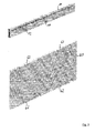
- Figure 1C shows a perspective view of a horizontal profile part according to an embodiment of the invention the sole representation.
- FIG. 2 shows a horizontal profile part according to an embodiment of the invention in connection with a wall element.
- FIG. 3A shows a perspective view of a horizontal profile part with lateral insertion part for attachment to a vertical column according to a first embodiment of the invention.
- FIG. 3B shows a perspective view of an attached to the vertical column horizontal profile part according to the first embodiment of the invention.
- FIG. 4 shows a perspective view of a horizontal profile part with fastening element for hanging on a vertical column according to a second embodiment of the invention.
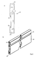
- FIG. 5A shows in cross-sectional view and FIG. 5B in perspective view a horizontal profile part according to an embodiment of the invention.
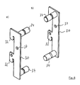
- FIG. 6 shows in perspective detail view insertion according to a first embodiment of the carrier system according to the invention.
- FIG. 7 shows a perspective detail view of a fastener according to a second embodiment of the carrier system according to the invention.
- the carrier system according to the invention consists of the three basic elements vertical columns, horizontal profile parts and male parts or fasteners for securing the horizontal profile parts to the vertical columns.
- Figure 1A shows a horizontal profile part with double-sided insertion for attachment to two vertical columns according to a first embodiment and Figure 1 B according to a second embodiment of the invention in disassembled state and Figure 1C an example of a horizontal profile part according to the invention in isolation and FIG. 2 in conjunction with a wall panel element.
- FIGS. 3 and 4 schematically show the attachment of a horizontal profile part to a vertical column according to the first and second embodiment of the invention
- FIG. 5A shows the horizontal profile part in cross-sectional view and FIG. 5B in perspective view.
- horizontal profile part has a preferably over the entire width of the horizontal profile part extending horizontal groove 12, which is particularly suitable for hanging boards, shelves, glass shelves, support elements, brackets and brackets of all kinds.
- the horizontal groove 12 has an upwardly facing L-shaped cross section, as in particular FIG. 5 easy to recognize.
- the horizontal profile part 10 is formed as a profile part, wherein in the upper region and in the lower region cavity openings 18 and 19 are formed, in which on both sides plug-in parts 30 can be inserted.
- the plug-in parts 30 also have hook elements 32, which can be suspended in fastening slots 22, which are formed in the vertical columns 20, as will be explained in detail later.
- the horizontal profile part 10 according to the invention is clearly visible, formed on its rear side by a pair of opposing grooves 16, 17 Insertion rail, in which fasteners 40 (see Figures 1 B, 4 and 7 ) are insertable, as will be explained in detail later.
- the horizontal profile member 10 according to a preferred variant on its top and / or on its underside holding and positioning means 14 to position a panel element or wall element 60 and hold.
- the holding and positioning means 14 are formed as bores in which in a Panedlelement 60 formed retaining pins can be inserted.
- the horizontal profile parts 10 serve as a support structure for a composite of several wall elements 60 wall structure, which has easy to install, flexibly shaped and a smooth, aesthetically pleasing surface.
- very flexible shelves, boards, hooks, fasteners or the like of various materials such as wood, glass, acrylic glass, plastic or metal can be used.
- the attachment of the horizontal profile parts 10 to the vertical columns 20 takes place alternatively either by means of two insertion parts 30, which in detail in FIG. 6 are shown or by means of at least two fasteners 40 (see detail in FIG. 7 ).
- the insertion parts 30 are provided with preferably cylindrical fastening pins 34, which are formed in the cavities 18, 19 (see FIG. 5 ) are inserted and are kept there by friction.
- the plug-in part 30 further has hook elements 32 for hooking into the vertical slots 22 formed in the horizontal columns 20.
- a right and a left side plug 30 is as in Figure 1A shown pushed as a final element in the horizontal part and this connected by simply hanging with a pair of horizontal columns 20.
- the serving as holding elements for a wall structure horizontal profile parts 10 are secured against rotation secured to the vertical columns 20.
- the lateral end faces of the plug-in parts 30 are flat and thus allow multiple elements can be juxtaposed and form a flat surface.
- In the lateral end face and a bore 37 may be formed, which in turn may serve for fastening and centering of centering pins of adjacent panel elements or the like.
- the horizontal profile part 10 can be fixed by means of at least two fastening elements 40 to a pair of horizontal columns.
- the fasteners 40 are inserted into the formed on the back of the horizontal profile part 10 rail 16, 17 and thus allow any horizontal positioning of the horizontal columns with respect to the horizontal profile part.
- a support against twisting is also given in this mounting variant.
- 50 can be attached without attachment hooks on the lateral end faces of the horizontal profile part closure elements to produce a flat, smooth lateral end face.
- Both attachment variants have in common that the horizontal columns 20 are hidden and thus a visually appealing impression can be achieved.
- the horizontal columns 20 may have a round or preferably a square cross-section and are provided with vertically spaced mounting slots 22 for hooking the horizontal profile parts.
- the vertical columns may be provided with fastening means (not shown) for attachment to a wall or may be freestanding by means of a foot portion (also not shown).
Landscapes
- Display Racks (AREA)
Abstract
Description
- Die Erfindung betrifft ein Trägersystem mit wenigstens zwei Vertikalsäulen, in welche Wandelemente, Tragelemente oder dergleichen beispielsweise zum Zwecke der Warenpräsentation einhängbar sind..
- Es sind eine große Anzahl von Trägersystemen für Warenpräsentationswände oder dergleichen bekannt, die je nach Anwendungszweck verschieden ausgestaltet sind.
- Das deutsche Gebrauchsmuster
DE 20 2005 002 395 U1 beschreibt ein Trägersystem für einstellbare Warenpräsentationsflächen bestehend aus einer senkrechten Fläche mit waagrechten Schlitzen, in welche horizontal angeordnete Warenpräsentationsborde einhängbar sind - Die
WO 93/11317 - Das aus der
WO 93/11317 - Der vorliegenden Erfindung liegt daher die Aufgabe zugrunde, ein Trägersystem mit wenigstens zwei, jeweils Befestigungsschlitze aufweisenden Vertikalsäulen vorzuschlagen, das eine flexible Montage sowohl von Wandelementen als auch von Tragelementen erlaubt und eine ästhetisch ansprechende Gestaltung auch der seitlichen Stirnflächen bietet.
- Gelöst wird die Aufgabe durch ein Trägersystem aufweisend wenigstens zwei Vertikalsäulen mit mehreren, vertikal voneinander beabstandeten Befestigungsschlitzen, wenigstens ein Horizontalprofilteil, welches auf seiner Vorderseite eine horizontal verlaufende Nut zum Einhängen von Tragelementen oder dergleichen aufweist, sowie wenigstens zwei Einsteckteile, welche seitlich als Abschlußelemente auf beide Enden des Horizontalprofilteils aufsteckbar und mittels eines Hakenelements in einen der Befestigungsschlitze der Vertikalsäulen einhängbar sind.
- Die im Horizontalprofilteil verlaufende horizontale Nut erlaubt ein flexibles Einhängen von Tragelementen, Regalbrettern oder dergleichen. Die seitlichen Einsteckteile sorgen für eine sichere Befestigung des Horizontalprofilteils an den Vertikalsäulen und bieten gleichzeitig eine ästhetisch ansprechende Gestaltung auch der seitlichen Stirnseiten des Trägersystems.
- Zur sicheren Befestigung weist das Einsteckteil vorzugsweise zwei zylinderförmige Stifte zum Einschieben in einen oberen und unteren Hohlraum des Horizontalprofilteils auf. Dabei kann das Einsteckteil zur Befestigung an der Vertikalsäule ebenfalls zwei übereinander angeordnete Hakenelemente zum Einhängen in benachbarte Befestigungsschlitze aufweisen.
- Um mehrere Wandelemente bündig nebeneinander aufstellen zu können, weist das Einsteckteil seitlich vorzugsweise ebene Flächen zur Abstützung an ein benachbartes Einsteckteil auf In der seitlich ebenen Fläche kann eine Bohrung zur Aufnahme eines Befestigungsstiftes eines benachbarten Wandelements oder dergleichen vorgesehen sein.
- Die der Erfindung zugrundeliegende Aufgabe wird ferner gelöst durch ein Trägersystem aufweisend wenigstens zwei Vertikalsäulen mit mehreren, vertikal voneinander beabstandeten Befestigungsschlitzen, wenigstens ein Horizontalprofilteil, welches auf seiner Vorderseite eine horizontal verlaufende Nut zum Einhängen von Tragelementen oder dergleichen und auf der Rückseite eine Schiene zum Einschieben von Befestigungselementen oder dergleichen aufweist, und wenigstens zwei Befestigungselemente, die in die auf der Rückseite des Horizontalprofilteils ausgebildete Schiene einschiebbar und in einen der Befestigungsschlitze der Vertikalsäulen einhängbar sind.
- Die in die auf der Rückseite des Horizontalprofilteils ausgebildeten Schiene einschiebbaren Befestigungselemente erlauben eine sichere Befestigung des Horizontalprofilteils an den Vertikalschienen unabhängig von deren Abstand. Das erfindungsgemäße Trägersystem ist daher flexibel an unterschiedliche Raumverhältnisse anpaßbar.
- Vorzugsweise wird die rückseitige Schiene durch zwei einander gegenüberliegende Horizontalnuten gebildet.
- Das Befestigungselement kann als L-förmiges Winkelteil ausgebildet sein
- Die im Horizontalprofilteil ausgebildete horizontal verlaufende Nut kann einen L-förmigen, nach oben weisenden Querschnitt aufweisen, der eine flexible und stabile Befestigung von Regalbrettern, Tragelementen etc. ermöglicht und eine ästhetisch ansprechende Gestaltung bietet, welche insbesondere für die Warenpräsentation wichtig ist.
- Vorzugsweise weist das Horizontalprofilteil auf seiner Ober- und/oder Unterseite Halte- und Positionierungsmittel zur Positionierung und zum Halten von Wand- oder Panelelementen auf. So dienen die Horizontalprofilteile als Stützstruktur für eine Wandstruktur, die stabil und einfach montierbar ist sowie eine glatte Oberfläche aufweist. Die Halte- und Positionierungsmittel können beispielsweise als Bohrungen ausgebildet sein, in welche in einem Paneel- oder Wandelement ausgebildete Haltestifte einsteckbar sind.
- Die Vertikalsäulen können einen runden oder quadratischen Querschnitt aufweisen, wobei letzterer eine zusätzliche Winkelstabilisierung der Horizontalelemente bietet
- Die Vertikalsäulen können entweder Befestigungsmittel zur Befestigung an einer Wand aufweisen oder mittels eines Fußteils freistehend ausgebildet sein.
- Die Erfindung wird im folgenden anhand von konkreten Ausführungsbeispielen unter Bezugnahme auf die beiliegenden Zeichnungen erläutert.
-
Figur 1A zeigt in perspektivischer Darstellung ein Horizontalprofilteil mit zwei zugehörigen Einsteckteilen gemäß einem ersten Ausführungsbeispiel der Erfindung. -
Figur 1 B zeigt in perspektivischer Darstellung ein Horizontalprofilteil mit zwei zugehörigen Befestigungselementen gemäß einem zweiten Ausführungsbeispiel der Erfindung. -
Figur 1C zeigt in perspektivischer Darstellung ein Horizontalprofilteil gemäß einem erfindungsgemäßen Ausführungsbeispiel der Alleindarstellung. -
Figur 2 zeigt ein Horizontalprofilteil gemäß einem Ausführungsbeispiel der Erfindung in Verbindung mit einem Wandelement. -
Figur 3A zeigt in perspektivischer Darstellung ein Horizontalprofilteil mit seitlichem Einsteckteil zum Einhängen an eine Vertikalsäule gemäß einem ersten Ausführungsbeispiel der Erfindung. -
Figur 3B zeigt in perspektivischer Darstellung ein an der Vertikalsäule eingehängtes Horizontalprofilteil gemäß dem ersten Ausführungsbeispiel der Erfindung. -
Figur 4 zeigt in perspektivischer Darstellung ein Horizontalprofilteil mit Befestigungselement zum Einhängen an eine Vertikalsäule gemäß einem zweiten Ausführungsbeispiel der Erfindung. -
Figur 5A zeigt in Querschnittsansicht undFigur 5B in perspektivischer Darstellung ein Horizontalprofilteil gemäß einem Ausführungsbeispiel der Erfindung. -
Figur 6 zeigt in perspektivischer Detailansicht Einsteckteile gemäß einem ersten Ausführungsbeispiel des erfindungsgemäßen Trägersystems. -
Figur 7 zeigt in perspektivischer Detailansicht ein Befestigungselement gemäß einem zweiten Ausführungsbeispiel des erfindungsgemäßen Trägersystems. - Die Erfindung wird im folgenden anhand von konkreten Ausführungsbeispielen im Detail erläutert.
- Das erfindungsgemäße Trägersystem besteht aus den drei Grundelementen Vertikalsäulen, Horizontalprofilteilen und Einsteckteilen bzw. Befestigungselementen zum Befestigen der Horizontalprofilteile an den Vertikalsäulen.
-
Figur 1A zeigt ein Horizontalprofilteil mit beidseitigen Einsteckteilen zur Befestigung an zwei Vertikalsäulen gemäß einem ersten Ausführungsbeispiel undFigur 1 B gemäß einem zweiten Ausführungsbeispiel der Erfindung in demontiertem Zustand undFigur 1C ein Beispiel eines erfindungsgemäßen Horizontalprofilteils in Alleindarstellung undFigur 2 in Verbindung mit einem Wandpaneelelement. - Die
Figuren 3 und 4 zeigen schematisch die Befestigung eines Horizontalprofilteils an einer Vertikalsäule gemäß erstem bzw. zweitem Ausführungsbeispiel der Erfindung -
Figur 5A zeigt das Horizontalprofilteil in Querschnittsdarstellung undFigur 5B in perspektivischer Ansicht. - Das in den
Figuren 1 bis 5 dargestellte und beispielsweise aus Aluminium gefertigte, insgesamt mit 10 bezeichnete Horizontalprofilteil weist eine sich vorzugsweise über die gesamte Breite des Horizontalprofilteils erstreckende Horizontalnut 12 auf, die sich insbesondere zum Einhängen von Brettern, Regalböden, Glasböden, Tragelementen, Bügeln und Halterungen aller Art eignet. In einer bevorzugten Variante weist die Horizontalnut 12 einen nach oben weisenden L-förmigen Querschnitt auf, wie insbesondere inFigur 5 gut zu erkennen ist. Wie aus der Bezeichnung hervorgeht ist das Horizontalprofilteil 10 als Profilteil ausgebildet, wobei im oberen Bereich und im unteren Bereich Hohlraumöffnungen 18 und 19 Ausgebildet sind, in welche an beiden Seiten Einsteckteile 30 einsteckbar sind. Die Einsteckteile 30 weisen außerdem Hakenelemente 32 auf, welche in Befestigungsschlitze 22 einhängbar sind, die in den Vertikalsäulen 20 ausgeformt sind, wie später noch im Detail erläutert werden wird. - Gemäß einem Ausführungsbeispiel weist das erfindungsgemäße Horizontalprofilteil 10, wie insbesondere in
Figur 5A gut zu erkennen ist, auf seiner Rückseite eine durch zwei einander gegenüberliegende Nuten 16, 17 gebildete Einsteckschiene auf, in welche Befestigungselemente 40 (sieheFiguren 1 B, 4 und 7 ) einschiebbar sind, wie später noch im Detail erläutert werden wird. - Ferner weist das Horizontalprofilteil 10 gemäß einer bevorzugten Variante an seiner Oberseite und/oder an seiner Unterseite Halte- und Positionierungsmittel 14 auf, um ein Paneelelement oder Wandelement 60 zu positionieren und zu halten. Vorzugsweise sind die Halte- und Positionierungsmittel 14 als Bohrungen ausgebildet, in welche in einem Panedlelement 60 ausgebildete Haltestifte einsteckbar sind. Durch diese Anordnung dienen die Horizontalprofilteile 10 als Stützstruktur für eine aus mehreren Wandelementen 60 zusammengesetzte Wandstruktur, die leicht montierbar, flexibel gestaltbar und eine glatte, ästhetisch ansprechende Oberfläche hat. In die Horizontalnut 12 können wie erwähnt ganz flexibel Regalböden, Bretter, Haken, Befestigungselemente oder ähnliches aus verschiedenen Materialien wie Holz, Glas, Acrylglas, Kunststoff oder Metall eingesetzt werden.
- Die Befestigung der Horizontalprofilteile 10 an den Vertikalsäulen 20 erfolgt alternativ entweder mittels zweier Einsteckteile 30, die im Detail in
Figur 6 dargestellt sind oder mittels wenigstens zweier Befestigungselemente 40 (siehe Detaildarstellung inFigur 7 ). - Die Einsteckteile 30 sind mit vorzugsweise zylinderförmigen Befestigungsstiften 34 versehen, die in die im Hohlprofilteil 10 ausgebildeten Hohlräume 18, 19 (siehe
Figur 5 ) einschiebbar sind und dort durch Reibung gebalten werden. Das Einsteckteil 30 weist ferner Hakenelemente 32 zum Einhängen in die in den Horizontalsäulen 20 ausgebildeten Vertikalschlitze 22 auf. Ein rechts- und ein linksseitiges Einsteckteil 30 wird wie inFigur 1A dargestellt als Abschlußelement in das Horizontalteil geschoben und dieses durch einfaches Einhängen mit einem Paar Horizontalsäulen 20 verbunden. Die als Halteelemente für eine Wandstruktur dienenden Horizontalprofilteile 10 sind so gegen Verdrehen gesichert an den Vertikalsäulen 20 angebracht. Die seitlichen Stirnflächen der Einsteckteile 30 sind eben ausgebildet und erlauben so, dass mehrere Elemente nebeneinandergestellt werden können und eine plane Oberfläche bilden. In der seitlichen Stirnfläche kann auch eine Bohrung 37 ausgebildet sein, welche wiederum zur Befestigung und Zentrierung von Zentrierstiften benachbarter Paneelelemente oder dergleichen dienen können. - Alternativ kann das Horizontalprofilteil 10 mittels wenigstens zweier Befestigungselemente 40 an einem Paar Horizontalsäulen befestigt werden. Die Befestigungselemente 40 werden in die auf der Rückseite des Horizontalprofilteils 10 ausgebildete Schiene 16, 17 eingeschoben und erlauben so eine beliebige horizontale Positionierung der Horizontalsäulen in Bezug auf das Horizontalprofilteil. Eine Abstützung gegen Verdrehen ist auch bei dieser Befestigungsvariante gegeben. Wie in
Figur 1 B gezeigt ist, können dabei an den seitlichen Stirnflächen des Horizontalprofilteils Abschlußelemente 50 ohne Befestigungshaken aufgesteckt werden, um eine ebene, glatte seitliche Stirnfläche herzustellen. - Beiden Befestigungsvarianten gemeinsam ist, dass die Horizontalsäulen 20 verdeckt werden und somit ein optisch ansprechender Eindruck erzielbar ist.
- Die Horizontalsäulen 20 können einen runden oder vorzugsweise einen quadratischen Querschnitt aufweisen und sind mit vertikal voneinander beabstandeten Befestigungsschlitzen 22 zum Einhängen der Horizontalprofilteile versehen. Die Vertikalsäulen können mit (nicht dargestellten) Befestigungsmitteln zur Befestigung an einer Wand versehen oder mittels eines (ebenfalls nicht dargestellten) Fußteils freistehend ausgebildet sein.
Claims (16)
- Trägersystem mit:- wenigstens zwei Vertikalsäulen (20) mit mehreren, vertikal voneinander beabstandeten Befestigungsschlitzen (22),- wenigstens einem Horizontalprofilteil (10), welches auf seiner Vorderseite eine horizontal verlaufende Nut (12) zum Einhängen von Tragelementen oder dgl aufweist,- wenigstens zwei Einsteckteilen (30), welche seitlich als Abschlußelemente auf beide Enden des Horizontalprofilteils (10) aufsteckbar und mittels eines Hakenelements (32) in einen der Befestigungsschlitze (22) der Vertikalsäulen (20) einhängbar sind.
- Trägersystem nach Anspruch 1, wobei das Einsteckteil (30) zwei zylinderförmige Befestigungsstifte (34) zum Einschieben in einen oberen (18) und unteren (19) Hohlraum des Horizontalprofilteils (20) aufweist.
- Trägersystem nach Anspruch 1 oder 2, wobei das Einsteckteil (30) zwei übereinander angeordnete Hakenelemente (32) zum Einhängen in benachbarte Befestigungsschlitze (22) der Vertikalsäulen (20) aufweist
- Trägersystem nach Anspruch 1, 2 oder 3, wobei das Einsteckteil (30) seitlich ebene Flächen zur Abstützung an ein benachbartes Trägersystem aufweist.
- Trägersystem nach Anspruch 4, wobei in der seitlichen ebenen Fläche eine Bohrung (37) ausgebildet ist.
- Trägersystem nach einem der Ansprüche 1 bis 5, wobei das Horizontalprofilteil (10) auf seiner Rückseite eine Schiene (16, 17) zum Einschieben von Befestigungselementen oder dgl aufweist, und welches Trägersystem ferner Befestigungselemente (40) aufweist, die in die auf der Rückseite des Horizontolprofilteils ausgebildete Schiene (16, 17) einschiebbar und in einen der Befestigungsschlitze (22) einer Vertikalsäule (20) einhängbar sind.
- Trägersystem mit:- wenigstens zwei Vertikalsäulen (20) mit mehreren, vertikal voneinander beabstandeten Befestigungsschlitzen (22),- wenigstens einem Horizontalprofilteil (10), welches auf seiner Vorderseite eine horizontal verlaufende Nut (12) zum Einhängen von Tragelementen oder dgl. und auf der Rückseite eine Schiene (16, 17) zum Einschieben von Befestigungselementen oder dgl. aufweist,- wenigstens zwei Befestigungselementen (40), die in die auf der Rückseite des Horizontalprofilteils ausgebildete Schiene (16, 17) einschiebbar und in einen der Befestigungsschlitze einer Vertikalsäule (20) einhängbar sind.
- Trägersystem nach Anspruch 6 oder 7, wobei die auf der Rückseite des Horizontolprofilteils ausgebildete Schiene durch zwei gegenüberliegende Horizontalnuten (16, 17) gebildet wird.
- Trägersystem nach Anspruch 6, 7 oder 8, wobei die Befestigungselemente (40) als L-förmige Winkelteile ausgebildet sind.
- Trägersystem nach einem der Ansprüche 1 bis 9, wobei die im Horizontalprofilteil (10) ausgebildete horizontal verlaufende Nut (12) einen L-förmigen, nach oben weisenden Querschnitt aufweist
- Trägersystem nach einem der Ansprüche 1 bis 10, wobei das Horizontalprofilteil (10) auf der Ober- und/oder Unterseite Halte- und Positionierungsmittel (14) zur Positionierung von Paneelelementen (60) oder dgl. aufweist.
- Trägersystem nach Anspruch 11, wobei die Halte- und Positionierungsmittel (14) als Bohrungen ausgebildet sind, in welche in einem Paneelelement (60) ausgebildete Haltestifte (62) einsteckbar sind.
- Trägersystem nach einem der Ansprüche 1 bis 10, wobei die Vertikalsäulen (20) einen runden Querschnitt aufweisen.
- Trägersystem nach einem der Ansprüche 1 bis 10, wobei die Vertikalsäulen (20) einen rechteckigen, insbesondere quadratischen Querschnitt aufweisen.
- Trägersystem nach einem der Ansprüche 1 bis 14, wobei die Vertikalsäulen (20) mittels eines Fußteils freistehend sind.
- Trägersystem nach einem der Ansprüche 1 bis 14, wobei die Vertikalsäulen (20) Befestigungsmittel zur Befestigung an einer Wand aufweisen.
Priority Applications (1)
| Application Number | Priority Date | Filing Date | Title |
|---|---|---|---|
| EP08101711A EP2090197A1 (de) | 2008-02-18 | 2008-02-18 | Trägersystem |
Applications Claiming Priority (1)
| Application Number | Priority Date | Filing Date | Title |
|---|---|---|---|
| EP08101711A EP2090197A1 (de) | 2008-02-18 | 2008-02-18 | Trägersystem |
Publications (1)
| Publication Number | Publication Date |
|---|---|
| EP2090197A1 true EP2090197A1 (de) | 2009-08-19 |
Family
ID=39580304
Family Applications (1)
| Application Number | Title | Priority Date | Filing Date |
|---|---|---|---|
| EP08101711A Withdrawn EP2090197A1 (de) | 2008-02-18 | 2008-02-18 | Trägersystem |
Country Status (1)
| Country | Link |
|---|---|
| EP (1) | EP2090197A1 (de) |
Cited By (7)
| Publication number | Priority date | Publication date | Assignee | Title |
|---|---|---|---|---|
| WO2019083632A1 (en) * | 2017-10-27 | 2019-05-02 | Elfa International Ab | CONFIGURABLE WALL STORAGE SYSTEM |
| US10306981B2 (en) | 2016-12-02 | 2019-06-04 | Altria Client Services Llc | Universal mounting system (UMS) and method of installing thereof |
| US10334970B2 (en) * | 2016-12-02 | 2019-07-02 | Altria Client Services Llc | Adaptive merchandising platform (AMP) mounting system and method of installing thereof |
| US11375812B2 (en) | 2018-09-12 | 2022-07-05 | Elfa International Ab | Wall-mounted, configurable storage system |
| US11717085B2 (en) | 2020-04-30 | 2023-08-08 | Elfa International Ab | Suspension system for storage components |
| US11849839B2 (en) | 2019-12-23 | 2023-12-26 | Elfa International Ab | Shelf storage system |
| US11910927B2 (en) | 2020-04-30 | 2024-02-27 | Elfa International Ab | Hang standard and storage system including the hang standard |
Citations (9)
| Publication number | Priority date | Publication date | Assignee | Title |
|---|---|---|---|---|
| US3976201A (en) * | 1975-03-12 | 1976-08-24 | Pacific Electricord Company | Supporting and displaying apparatus for merchandise items |
| FR2575052A1 (fr) * | 1984-12-21 | 1986-06-27 | Lagier Cie | Dispositif destine a equiper un presentoir, ou similaire, pour servir de support a une serie de tiges de suspension d'articles divers, et meubles presentoirs equipes d'un tel dispositif |
| GB2218898A (en) * | 1988-05-23 | 1989-11-29 | Robert P Donarte | Shop fitting structure and system |
| WO1993011317A1 (en) | 1991-12-02 | 1993-06-10 | Castillo Haucke J M Del | Modular panel wall structure |
| GB2275601A (en) * | 1993-02-15 | 1994-09-07 | Fredrick Usher | A display system |
| FR2741793A1 (fr) * | 1995-11-30 | 1997-06-06 | Benazeth Frederic | Systeme de panneaux en tole pliee servant de fond aux meubles gondoles de magasins et pouvant recevoir des crochets supports d'objets |
| GB2313293A (en) * | 1996-05-22 | 1997-11-26 | Fredrick Usher | Hook and slot connector with locking device |
| DE202005006607U1 (de) * | 2005-04-26 | 2005-06-30 | Visplay International Ag | Aufhängevorrichtung zur Warenpräsentation mit einer Vertikalstütze und darin einhängbarem Tragarm |
| DE202005002395U1 (de) | 2005-02-09 | 2005-11-17 | Hakemann, Edgar, Dipl.-Ing. | Trägersystem für einstellbare Warenpräsentationsflächen |
-
2008
- 2008-02-18 EP EP08101711A patent/EP2090197A1/de not_active Withdrawn
Patent Citations (9)
| Publication number | Priority date | Publication date | Assignee | Title |
|---|---|---|---|---|
| US3976201A (en) * | 1975-03-12 | 1976-08-24 | Pacific Electricord Company | Supporting and displaying apparatus for merchandise items |
| FR2575052A1 (fr) * | 1984-12-21 | 1986-06-27 | Lagier Cie | Dispositif destine a equiper un presentoir, ou similaire, pour servir de support a une serie de tiges de suspension d'articles divers, et meubles presentoirs equipes d'un tel dispositif |
| GB2218898A (en) * | 1988-05-23 | 1989-11-29 | Robert P Donarte | Shop fitting structure and system |
| WO1993011317A1 (en) | 1991-12-02 | 1993-06-10 | Castillo Haucke J M Del | Modular panel wall structure |
| GB2275601A (en) * | 1993-02-15 | 1994-09-07 | Fredrick Usher | A display system |
| FR2741793A1 (fr) * | 1995-11-30 | 1997-06-06 | Benazeth Frederic | Systeme de panneaux en tole pliee servant de fond aux meubles gondoles de magasins et pouvant recevoir des crochets supports d'objets |
| GB2313293A (en) * | 1996-05-22 | 1997-11-26 | Fredrick Usher | Hook and slot connector with locking device |
| DE202005002395U1 (de) | 2005-02-09 | 2005-11-17 | Hakemann, Edgar, Dipl.-Ing. | Trägersystem für einstellbare Warenpräsentationsflächen |
| DE202005006607U1 (de) * | 2005-04-26 | 2005-06-30 | Visplay International Ag | Aufhängevorrichtung zur Warenpräsentation mit einer Vertikalstütze und darin einhängbarem Tragarm |
Cited By (19)
| Publication number | Priority date | Publication date | Assignee | Title |
|---|---|---|---|---|
| US11707144B2 (en) | 2016-12-02 | 2023-07-25 | Altria Client Services Llc | Method of installing mounting system with support bracket |
| US10306981B2 (en) | 2016-12-02 | 2019-06-04 | Altria Client Services Llc | Universal mounting system (UMS) and method of installing thereof |
| US10334970B2 (en) * | 2016-12-02 | 2019-07-02 | Altria Client Services Llc | Adaptive merchandising platform (AMP) mounting system and method of installing thereof |
| US10548417B2 (en) | 2016-12-02 | 2020-02-04 | Altria Client Services Llc | Adaptive merchandising platform (AMP) mounting system and method of installing thereof |
| US10888179B2 (en) | 2016-12-02 | 2021-01-12 | Altria Client Services Llc | Support bracket for mounting system |
| US11160395B2 (en) | 2016-12-02 | 2021-11-02 | Altria Client Services Llc | Method of making support bracket |
| US11178964B2 (en) | 2016-12-02 | 2021-11-23 | Altria Client Services Llc | Mounting system with horizontally-slideable bracket and support bracket |
| US11864649B2 (en) | 2016-12-02 | 2024-01-09 | Altria Client Services Llc | Method of installing mounting system with insertable brackets and support brackets |
| US11583074B2 (en) | 2017-10-27 | 2023-02-21 | Elfa International Ab | Wall-mounted, configurable storage system |
| USD984257S1 (en) | 2017-10-27 | 2023-04-25 | Elfa International Ab | Cantilevered bracket for a cantilevered storage system |
| WO2019083632A1 (en) * | 2017-10-27 | 2019-05-02 | Elfa International Ab | CONFIGURABLE WALL STORAGE SYSTEM |
| TWI834709B (zh) * | 2017-10-27 | 2024-03-11 | 瑞典商艾法國際公司 | 用於直立地安裝在牆壁安裝式儲存系統的標準件 |
| US12185833B2 (en) | 2017-10-27 | 2025-01-07 | Elfa International Ab | Wall-mounted, configurable storage system |
| US12593914B2 (en) | 2017-10-27 | 2026-04-07 | Elfa International Ab | Storage components for a configurable storage system |
| US11375812B2 (en) | 2018-09-12 | 2022-07-05 | Elfa International Ab | Wall-mounted, configurable storage system |
| US11849839B2 (en) | 2019-12-23 | 2023-12-26 | Elfa International Ab | Shelf storage system |
| US11717085B2 (en) | 2020-04-30 | 2023-08-08 | Elfa International Ab | Suspension system for storage components |
| US11910927B2 (en) | 2020-04-30 | 2024-02-27 | Elfa International Ab | Hang standard and storage system including the hang standard |
| US12446691B2 (en) | 2020-04-30 | 2025-10-21 | Elfa International Ab | Suspension system for storage components |
Similar Documents
| Publication | Publication Date | Title |
|---|---|---|
| EP2238871B1 (de) | System für die Herstellung einer an einer Wand, insbesondere Raumwand, montierbaren Multifunktionswand und Verfahren zur Herstellung und Montage einer Multifunktionswand | |
| EP2066198B1 (de) | Präsentationsanordnung | |
| DE102011050615B4 (de) | Profilelement für Möbel, insbesondere Regale | |
| DE102007058474B4 (de) | Befestigungssystem und Konsole | |
| AT505493B1 (de) | Verkleidung | |
| DE102010001661B4 (de) | Profil für ein Regal o. dgl. zur Warenpräsentation sowie Regal o.dgl. mit dem Profil | |
| DE3688113T2 (de) | Elementensatz fuer die einrichtung von ausstellungsraeumen, geschaeften und anderen orten. | |
| DE10044969A1 (de) | Wandprofilleiste | |
| DE102005004654B4 (de) | Flexibles Präsentationssystem und Profilschiene hierfür | |
| DE202008001773U1 (de) | Regalsystem, insbesondere zur Präsentation von Waren | |
| DE4023685C1 (en) | Support rail element for goods - has openings in rail sections to allow fitting of hooked brackets | |
| DE20216231U1 (de) | Bausatz zur Bildung eines Trennwandsystems | |
| CH686966A5 (de) | Universell verwendbare Trenn- bzw. Ausstellungs- oder Praesentationswand. | |
| EP2260744A1 (de) | Eckregal | |
| DE9210953U1 (de) | Metallregal | |
| DE202006017766U1 (de) | Präsentationssystem für Waren u.dgl. | |
| DE202009009001U1 (de) | Wandbefestigungssystem zur Montage eines Paneelsystems | |
| DE202009003227U1 (de) | Traggerüst für ein Innenwand-Verkleidungssystem | |
| DE102019105794A1 (de) | Wandkonstruktion, insbesondere für den Messe- oder Museumsbau, und Verfahren zum Aufbau der Wandkonstruktion | |
| DE3013383A1 (de) | Bausatz zur erstellung einer wandvertaefelung | |
| WO2004014188A1 (de) | Regal | |
| DE202007017003U1 (de) | Befestigungssystem zur beabstandeten Anordnung von Regalböden | |
| DE20022725U1 (de) | Wandprofilleiste | |
| AT11053U1 (de) | Aufhängevorrichtung | |
| DE202004007841U1 (de) | Aufbau für eine Glastrennwand |
Legal Events
| Date | Code | Title | Description |
|---|---|---|---|
| PUAI | Public reference made under article 153(3) epc to a published international application that has entered the european phase |
Free format text: ORIGINAL CODE: 0009012 |
|
| AK | Designated contracting states |
Kind code of ref document: A1 Designated state(s): AT BE BG CH CY CZ DE DK EE ES FI FR GB GR HR HU IE IS IT LI LT LU LV MC MT NL NO PL PT RO SE SI SK TR |
|
| AX | Request for extension of the european patent |
Extension state: AL BA MK RS |
|
| 17P | Request for examination filed |
Effective date: 20100219 |
|
| 17Q | First examination report despatched |
Effective date: 20100326 |
|
| AKX | Designation fees paid |
Designated state(s): AT BE BG CH CY CZ DE DK EE ES FI FR GB GR HR HU IE IS IT LI LT LU LV MC MT NL NO PL PT RO SE SI SK TR |
|
| 19U | Interruption of proceedings before grant |
Effective date: 20101220 |
|
| 19W | Proceedings resumed before grant after interruption of proceedings |
Effective date: 20120702 |
|
| RAP1 | Party data changed (applicant data changed or rights of an application transferred) |
Owner name: RUDOLF BOHNACKER SYSTEME GMBH |
|
| STAA | Information on the status of an ep patent application or granted ep patent |
Free format text: STATUS: THE APPLICATION IS DEEMED TO BE WITHDRAWN |
|
| 18D | Application deemed to be withdrawn |
Effective date: 20130103 |