EP2090262B1 - Appareil dentaire - Google Patents
Appareil dentaire Download PDFInfo
- Publication number
- EP2090262B1 EP2090262B1 EP09152063.5A EP09152063A EP2090262B1 EP 2090262 B1 EP2090262 B1 EP 2090262B1 EP 09152063 A EP09152063 A EP 09152063A EP 2090262 B1 EP2090262 B1 EP 2090262B1
- Authority
- EP
- European Patent Office
- Prior art keywords
- housing
- dental device
- damping element
- stand foot
- frame
- Prior art date
- Legal status (The legal status is an assumption and is not a legal conclusion. Google has not performed a legal analysis and makes no representation as to the accuracy of the status listed.)
- Active
Links
Images



Classifications
-
- A—HUMAN NECESSITIES
- A61—MEDICAL OR VETERINARY SCIENCE; HYGIENE
- A61C—DENTISTRY; APPARATUS OR METHODS FOR ORAL OR DENTAL HYGIENE
- A61C5/00—Filling or capping teeth
- A61C5/60—Devices specially adapted for pressing or mixing capping or filling materials, e.g. amalgam presses
- A61C5/68—Mixing dental material components for immediate application to a site to be restored, e.g. a tooth cavity
Definitions
- the invention relates to a dental appliance, according to the preamble of claim 1, which is designed in particular as a dental mixing device.
- Such a dental device is for example from the DE-GM 93 09 794 known.
- the vibrating device described therein has bearing points of a frame, which is tuned so that when vibrating dental materials such as gypsum, amalgam or the like, the natural frequency of the frame is achieved as quickly as possible together with the vibrator.
- the frame is clamped at bearings between two elastically prestressed damping elements.
- the damping element will pass through a pin, which compresses them and sets in so far under bias.
- a grub screw which passes through the damping elements and whose effective length is adjustable via a lock nut.
- the pin is mounted on the housing, wherein the storage via locking washers and additionally via centering takes place.
- Another disadvantage of the known vibrating device is due to the dependence of the vibrating device on the amount of dental material to be vibrated. With a high degree of filling, a relatively large mass has to be moved in comparison to the mass of the vibrating device, so that the vibrating device, as it were, starts to hop. This burdens the pad, for example, the table in question in the dental office or dental laboratory on which the vibrator is placed. In addition, by the swinging of the housing there provided cable entries, bearings, etc. are relatively heavily loaded.
- a dental amalgam mixing device that includes a damper and shock absorber assembly to absorb or damp vibrations during operation.
- the amalgam mixing device has a housing and an at least partially disposed in the housing frame, which carries a drive source and a drive arm, wherein at least two damper units are mounted within the housing.
- Each damper unit comprises a first damper element and a second damper element that can be compressed and generate an elastic restoring force when compressed.
- each damper unit includes a plurality of washers located on the upper and lower end faces of the first and second damper members.
- the first damper unit is connected to a bottom plate of the housing and by means of a transverse retaining plate - with the second damper unit. Both damper units are thus attached via the support plate by means of a plurality of screws with the frame of the housing, which significantly complicates the construction and also significantly loads the pad on which the mixing device is placed.
- the invention has for its object to provide a dental device according to the preamble of claim 1, which is improved in terms of long-term stability, both device-internal and with respect to the pad of the device.
- the housing itself is used for the formation of stop surfaces for the damping elements. This allows a lateral displacement and relative movement between the ends of the Dämfungs institute and the housing avoid or cumbersome. Even if, for example, a bearing plate is provided on the upper side of the damping elements on the upper abutment surface of the housing, it can be pressed firmly into the device housing.
- elastomer foam for the damping elements instead of coil springs, the bearings are In any case less loaded, since typically also hard-made elastomer foam is much softer than metal.
- the base is designed in a special way, so that the stand pressure is so deformed by the contact pressure of the dental appliance on the respective bearing point that the deflection is at least partially compensated by the contact pressure.
- the levers acting in relation to an imaginary pivot point are opposite in this respect and when load introduction, for example by the shaking movement, the tilting moment induced by the frame is compensated for this imaginary pivot point by the opposite tilting moment between the housing and the contact ring.
- the increase of the downwardly acting force on the lower abutment surface leads to the increase of a counterforce that generates the pad on the uprising ring, so that the force inputs take place in each case proportional and thus compensation is possible.
- the upwardly facing stop surface of the housing is provided in the region of the base and preferably on this base. This is the only way to achieve the desired introduction of force particularly favorable, and the lateral guidance can be optimized by appropriate shaping of the damping element on the one hand and the base on the other hand.
- the upper damping element is made softer than the lower damping element.
- the main force is down by the weight of the frame, so that the force differences are compensated during clamping and both damping elements are pressed together by about the same amount.
- the bias can be set in any suitable manner fix, by a suitable choice of the dimensions of the housing, wherein preferably the bias voltage is less than 30 percent, preferably only 10 to 20 percent of the introduced forces.
- a guide element which guides the frame laterally on the damping elements.
- the guide member may be formed either as the damping elements directly embracing guide sleeve or as a guide pin which fills the damping elements inside in a through hole, the height of the guide pin is preferably selected so that the guide pin is slightly less than half the height of the respective through hole occupies.
- the base is formed of a hard elastomer, wherein the above-described deformation, however, additionally serves to damp the vibration transmission from the vibrator to the base.
- the housing has a bottom plate in which the feet are mounted. It is in two parts, and an inner upper housing part is firmly bolted to the surrounding housing part.
- the bottom plate as part of the housing is preferably received in the circumferential groove of the base, wherein the base can be circular, but also, for example, square with rounded corners.
- the base can be circular, but also, for example, square with rounded corners.
- it has on its underside a trough-like depression, and the lower, upwardly facing stop surface of the housing is provided at the bottom of a sleeve-like recess of the base, which also has a center pin to improve the lateral guidance.
- the lower region of the lower damping element is preferably surrounded by the base and in addition to the center pin, which cooperates with its through hole, guided laterally.
- the base preferably protrudes downwards a little in relation to the dental appliance, and the pedestal is preferably designed such that it can be snapped into the base plate from below.
- the housing of the dental device according to the invention which is preferably designed as a dental mixing device or vibrator, oscillates very little, even if large quantities of dental material are processed, and that the base on which the dental device is placed, a subjected to even lower load.
- This point of view is beneficial if the engine is mounted with the mixing arm via an elastic bearing element or additional spring element on the frame.
- the spring element already allows a vibration reduction for the frame relative to the vibration of the engine, so that insofar a double vibration decoupling can be realized.
- the resonance frequencies of both the frame and the housing can be adapted to the requirements in a wide range.
- the resonant frequency of the housing can be adjusted to a value that is significantly different from the exciter frequency, that is, for example, one third to one fifth of this exciter frequency.
- the lower damping element is supported on a stand.
- a guide element in particular a guide pin, at least partially protrudes into the upper and the lower Dämpfungslement and that the guide element also passes through a passage opening of the frame.
- the upper damping elements is softer than the lower damping element.
- each Dämpfungslement is sleeve-shaped and has a central through hole whose diameter corresponds substantially to the diameter of the guide pin.
- the damping elements are formed from an elastomeric foam, in particular polyurethane, by a compression spring or an adjustable air cushion.
- the first upwardly facing abutment surface of the housing is part of a stand, which passes through a through bore of the housing and projects beyond the housing in the vertical direction.
- a stand supports the lower damping element and in particular is formed of a hard elastomer and that in particular the lower region of the lower damping elements is surrounded by the stand.
- the stand has on its underside a trough-like depression and has on its circular outer contour a circumferential groove into which the edge region of the through hole of the housing protrudes.
- the guide element is fixedly arranged in the passage opening of the frame.
- the upper region of the upper Dämpfungslement is surrounded by a part of the housing and is supported in particular against the housing.
- the housing is formed at least in two parts and that in particular the housing covers the frame in the manner of a panel.
- the motor and / or the mixing arm are mounted in a spring element supported on the frame, in particular on the hard elastomer part.
- the at least one bearing point and / or the housing is supported on a stand, which deforms by the contact pressure of the bearing so that the deflection is compensated by the contact pressure at least partially.
- the motor is mounted on at least one elastic bearing element on the frame and that the spring element can be snapped in particular on the frame for mounting.
- a tilting moment is introduced to the stand by the weight of the dental device, which tends to raise the bottom of the stand.
- the feet of the dental device are taken with its bearing point inside the dental unit and the Aufstand Scheme each stand relative to the dental device in the other by a few, in particular by less than one centimeter, protrudes.
- the frame of the dental device is supported on the stand and the housing covers the frame in the manner of a panel.
- the stand is each formed substantially circularly symmetrical and has a vertical axis of movement, based on which deforms the stand when the load increases symmetrically.
- the stand is guided via a hinge on the bottom plate and is supported centrally on the main bearing on the frame of the dental device.
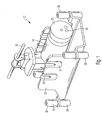
- a dental device 10 has a frame 12 which carries a motor 14 which drives a mixing arm 16.
- the motor has an asymmetrical bearing for this purpose, which causes the mixing arm 16 to vibrate.
- the mixing arm 16 is mounted on the substantially U-shaped frame 12 via spring elements 18.
- the engine for this purpose not shown pins, which rest in V-shaped cutouts 20 which are provided in the spring elements 18.
- the spring elements 18 are snapped into matching recesses of the side legs of the frame 12, so that the motor 14 is suspended so far resiliently on the frame 12.
- the motor 14 further includes a flywheel 22 with an asymmetric mass, which serves as mass balance for the movements of the mixing arm 16, wherein corresponding holes 24 are provided in the flywheel 22 asymmetrically for this purpose.
- the frame 12 is mounted on four bearings on a housing of the dental device 10, of which three bearings are visible.
- Each bearing 30 has an upper damping element 32 and a lower damping element 34.
- the upper damping element 32 is supported with its upper end on a downwardly facing stop surface of the housing, and the lower damping element 34 is supported at its lower end to an upwardly facing stop surface of the housing.
- the upper damping element 32 is ever softer than the lower damping element 34, which additionally has to bear the weight of the motor, the mixing arm and the frame.
- the damping element 32 and 34 are each slightly convex. They are preferably made of polyurethane elastomer foam, but basically also a realization by a spiral compression spring is possible.
- Fig. 2 shows a bearing 30 in an enlarged view and in section.
- like reference numerals indicate like parts. It can be seen that the frame 12 is held clamped between the upper damping element 32 and the lower damping element 34.
- a guide pin 40 is fixedly mounted on the frame 12, which is guided in through holes 42 in the damping element 32 and 34 and generates a lateral support of the frame 12.
- the damping elements 32 and 34 are held clamped by a housing 44.
- the housing 44 has an upper part 46, which has a cup-shaped recess 48, in which the upper end of the damping element 32 is guided. There, insofar as a downwardly facing stop surface 50 of the housing is formed.
- a screw 47 is attached, the two parts braced against each other and thereby sets the damping elements 32 and 34 under tension.
- a base 52 is also realized, which is mounted in a bottom plate 54 of the housing 44, and although via a groove 56 which is formed circumferentially on the base 52.
- the base 52 forms an upwardly facing stop surface 58 of the housing, which supports the damping element 34.
- a side guide is also formed via a center pin 60, which extends from the base 52, starting in the through hole.
- the base 52 is loaded by the additional weight load in the area of the stop surface 53.
- an annular footprint 62 is provided in the outer region, which extends around a depression 64 formed in the manner of a negative dome.
- the trough 64 extends in this respect.
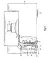
- Fig. 2 shown position of the stand 52 is in Fig. 3 shown again.
- Fig. 4 the stand shown in the additional loaded state.
- the trough 64 is much flatter. Due to the additional contact pressure on the contact surface 53, this deforms, mainly in the central region, ie adjacent the center pin 60. To an imaginary pivot point 70 arises insofar as a tilting moment, which makes the trough 64 flatter.
- the total load on the weight is increased in total by the additional burden of the frame, the extent that engages in the region of the groove 56.
- an opposing pressure around the fulcrum 70, and with proper interpretation, these two moments are compensated so that even with additional load of the stand does not additionally spring, the distance between the pad 72 and the groove 56 and thus the housing 44 so far constant remains.
- FIG. 5 Another embodiment of a dental device according to the invention is made Fig. 5 seen. Again, corresponding reference numerals indicate the same or corresponding parts.
- the upper part 46 of the housing 44 is pulled down to the area of the bottom plate 54 and supported there, so that there is an even fixed distance setting.
- the distance fixing is also off Fig. 6 in an enlarged view.
Landscapes
- Health & Medical Sciences (AREA)
- Oral & Maxillofacial Surgery (AREA)
- Dentistry (AREA)
- Epidemiology (AREA)
- Life Sciences & Earth Sciences (AREA)
- Animal Behavior & Ethology (AREA)
- General Health & Medical Sciences (AREA)
- Public Health (AREA)
- Veterinary Medicine (AREA)
- Dental Tools And Instruments Or Auxiliary Dental Instruments (AREA)
Claims (15)
- Appareil dentaire, en particulier appareil mélangeur dentaire, avec un boîtier et un cadre (12) logé au moins partiellement dans le boîtier, lequel supporte au moins un moteur (14) ainsi qu'un bras mélangeur (16) et est monté sur au moins deux, préférentiellement au moins trois, et en particulier quatre points d'appui (30) à l'intérieur du boîtier, chacun desdits points d'appui (30) étant fixé entre un élément d'amortissement supérieur et un élément d'amortissement inférieur (32, 34), élastiques et pré-contraints,
caractérisé en ce que l'élément d'amortissement inférieur (34) s'appuie contre une première surface de butée (58) orientée vers le haut, et l'élément d'amortissement supérieur (32) contre une deuxième surface de butée (50) du boîtier (44), orientée vers le bas. - Appareil dentaire selon la revendication 1, caractérisé en ce que l'élément d'amortissement inférieur (34) repose sur un pied d'appui (52).
- Appareil dentaire selon la revendication 1 ou 2, caractérisé en ce qu'un élément de guidage, en particulier un axe de guidage (40), pénètre au moins partiellement dans l'élément d'amortissement supérieur et l'élément d'amortissement inférieur (32, 34), et en ce que ledit élément de guidage traverse une ouverture de passage du cadre (12).
- Appareil dentaire selon l'une des revendications précédentes, caractérisé en ce que l'élément d'amortissement supérieur (32) est plus mou que l'élément d'amortissement inférieur (34).
- Appareil dentaire selon la revendication 3 ou 4, caractérisé en ce que chaque élément d'amortissement (32, 34) est réalisé en forme de manchon et présente un alésage traversant (42) dont le diamètre correspond sensiblement au diamètre de l'axe de guidage (40).
- Appareil dentaire selon l'une des revendications précédentes, caractérisé en ce que les éléments d'amortissement (32, 34) sont constitués d'une mousse élastomère, en particulier polyuréthane, ou d'un ressort de pression ou d'un coussin d'air ajustable.
- Appareil dentaire selon l'une des revendications précédentes, caractérisé en ce que la première surface de butée (58) orientée vers le haut du boîtier (44) fait partie d'un pied d'appui (52) traversant un alésage traversant du boîtier (44) et dépassant du boîtier (44) vers le bas en direction verticale.
- Appareil dentaire selon la revendication 7, caractérisé en ce que le pied d'appui (52) soutient l'élément d'amortissement inférieur (34) et est en particulier constitué d'un élastomère dur, et en ce que la zone inférieure de l'élément d'amortissement inférieur (34) est en particulier entourée par le pied d'appui (52).
- Appareil dentaire selon la revendication 7 ou 8, caractérisé en ce que le pied d'appui (52) présente un évidement en forme de cuvette (64) sur sa face inférieure et est pourvu d'une rainure (56) périphérique sur son contour extérieur circulaire, où s'engage la partie de bordure de l'alésage traversant du boîtier (44).
- Appareil dentaire selon l'une des revendications 3 à 9, caractérisé en ce que l'élément de guidage est fixement disposé dans l'ouverture de passage du cadre (12).
- Appareil dentaire selon l'une des revendications précédentes, caractérisé en ce que le moteur (14) et/ou le bras mélangeur (16) sont montés de manière oscillante sur le cadre (12) au moyen d'au moins un élément d'appui élastique.
- Appareil dentaire selon l'une des revendications précédentes, caractérisé en ce que le moteur (14) et le bras mélangeur (16) sont montés par des éléments à ressort (18) sur le cadre (12) sensiblement en forme de U.
- Appareil dentaire selon l'une des revendications 2 à 12, caractérisé en ce qu'un couple de basculement est appliqué dans le pied d'appui par la force exercée sur le pied d'appui (52), lequel soulève le boîtier coopérant avec le pied d'appui dans une mesure où le pied d'appui est comprimé verticalement.
- Appareil dentaire selon l'une des revendications précédentes, caractérisé en ce que la zone d'appui de chaque pied d'appui (52) dépasse de la face inférieure du boîtier (44) vers le bas en direction verticale, en particulier de moins d'un centimètre.
- Appareil dentaire selon l'une des revendications 2 à 14, caractérisé en ce que le pied d'appui (52) est prévu sensiblement avec une symétrie circulaire et présente un axe de déplacement vertical, par rapport auquel le pied d'appui (52) se déforme symétriquement en cas d'accroissement de la contrainte.
Applications Claiming Priority (1)
| Application Number | Priority Date | Filing Date | Title |
|---|---|---|---|
| DE102008008919A DE102008008919B4 (de) | 2008-02-13 | 2008-02-13 | Dentalgerät |
Publications (3)
| Publication Number | Publication Date |
|---|---|
| EP2090262A2 EP2090262A2 (fr) | 2009-08-19 |
| EP2090262A3 EP2090262A3 (fr) | 2009-09-16 |
| EP2090262B1 true EP2090262B1 (fr) | 2013-05-15 |
Family
ID=40627293
Family Applications (1)
| Application Number | Title | Priority Date | Filing Date |
|---|---|---|---|
| EP09152063.5A Active EP2090262B1 (fr) | 2008-02-13 | 2009-02-04 | Appareil dentaire |
Country Status (3)
| Country | Link |
|---|---|
| US (1) | US8177416B2 (fr) |
| EP (1) | EP2090262B1 (fr) |
| DE (1) | DE102008008919B4 (fr) |
Families Citing this family (1)
| Publication number | Priority date | Publication date | Assignee | Title |
|---|---|---|---|---|
| ES2874555T3 (es) * | 2016-12-15 | 2021-11-05 | Ivoclar Vivadent Ag | Dispositivo para sujetar una disposición de supraestructura y pilar de implante dental |
Family Cites Families (8)
| Publication number | Priority date | Publication date | Assignee | Title |
|---|---|---|---|---|
| JPS4856894U (fr) * | 1971-10-29 | 1973-07-20 | ||
| US4125335A (en) * | 1977-02-03 | 1978-11-14 | Blume Horst K | Agitator system |
| DE3106690A1 (de) * | 1981-02-23 | 1982-09-09 | Klöckner-Humboldt-Deutz AG, 5000 Köln | Gummifeder fuer die elastische lagerung von maschinen |
| DE3919775C2 (de) * | 1989-06-16 | 1994-09-01 | Daimler Benz Ag | Abstützlager |
| DE9309794U1 (de) | 1993-07-01 | 1994-11-10 | Maschinenbau Harnisch & Rieth GmbH & Co, 73650 Winterbach | Rüttelvorrichtung für den Dentalbereich |
| JPH09126274A (ja) * | 1995-10-27 | 1997-05-13 | Ishikawajima Harima Heavy Ind Co Ltd | 宇宙用機器の防振構造 |
| AU2003273452B2 (en) * | 2002-08-01 | 2008-06-12 | Bertin Technologies S.A | Device for fast vibration of tubes containing samples |
| DE202006019709U1 (de) * | 2006-12-28 | 2007-03-08 | Wang, Shu-Lung, San-Chung | Stoßdämpfer-Dämpfungsanordnung für eine Amalgam-Mischvorrichtung |
-
2008
- 2008-02-13 DE DE102008008919A patent/DE102008008919B4/de active Active
-
2009
- 2009-02-04 EP EP09152063.5A patent/EP2090262B1/fr active Active
- 2009-02-13 US US12/378,492 patent/US8177416B2/en active Active
Also Published As
| Publication number | Publication date |
|---|---|
| EP2090262A2 (fr) | 2009-08-19 |
| DE102008008919B4 (de) | 2011-07-21 |
| US8177416B2 (en) | 2012-05-15 |
| DE102008008919A1 (de) | 2009-08-27 |
| US20090201762A1 (en) | 2009-08-13 |
| EP2090262A3 (fr) | 2009-09-16 |
Similar Documents
| Publication | Publication Date | Title |
|---|---|---|
| EP0544175B1 (fr) | Pied de support de machine | |
| EP3017738B1 (fr) | Pied de support d'un appareil, notamment d'une machine de cuisine de table | |
| DE2353868A1 (de) | Pneumatisches lager und stossdaempfer | |
| DE2051626A1 (de) | Einrichtung zur Erzeugung einer Vibrations Gegenkraft | |
| AT516245B1 (de) | Unterbaukonstruktion zur Erhöhung der Erdbebensicherheit eines Hochspannungsbauteils | |
| DE4111318A1 (de) | Hydraulische, buchsenfoermige daempfungsvorrichtung | |
| DE69918114T2 (de) | Ritzwerkzeug | |
| DE102007013700B4 (de) | Dentalgeräterüttelvorrichtung | |
| EP2208693B1 (fr) | Convoyeur linéaire de vibrations | |
| AT389791B (de) | Federnd befestigte halteeinrichtung fuer ein mikrophon | |
| DE3106690A1 (de) | Gummifeder fuer die elastische lagerung von maschinen | |
| DE10353907B4 (de) | Schwingungsisolationsvorrichtung insbesondere für den Erdbebenschutz von Gebäuden | |
| EP3698067B1 (fr) | Amortisseur de vibration, en particulier pour une armoire de distribution | |
| DE69915065T2 (de) | Reissnadel | |
| DE102008008919B4 (de) | Dentalgerät | |
| DE1965583A1 (de) | Antivibrations-Abstuetzung | |
| DE3938383C1 (fr) | ||
| EP1327726B1 (fr) | Dispositif amortisseur de vibrations règlable | |
| EP2659810B1 (fr) | Pied de support d'un appareil, notamment d'une machine de cuisine de table | |
| DE10233023B3 (de) | Schwingungsisolator | |
| EP0457058B1 (fr) | Appareil à haute tension | |
| WO2009024329A1 (fr) | Tabouret à suspension | |
| DE10233804B3 (de) | Schwingungsisolator | |
| DE2744680C2 (de) | Korpuskularstrahloptisches Gerät mit einem in mindestens einem Lager sitzenden Objekthalter | |
| DE102006048887B4 (de) | Schwingungstilger mit veränderbarer Tilgereigenfrequenz |
Legal Events
| Date | Code | Title | Description |
|---|---|---|---|
| PUAI | Public reference made under article 153(3) epc to a published international application that has entered the european phase |
Free format text: ORIGINAL CODE: 0009012 |
|
| PUAL | Search report despatched |
Free format text: ORIGINAL CODE: 0009013 |
|
| AK | Designated contracting states |
Kind code of ref document: A2 Designated state(s): AT BE BG CH CY CZ DE DK EE ES FI FR GB GR HR HU IE IS IT LI LT LU LV MC MK MT NL NO PL PT RO SE SI SK TR |
|
| AX | Request for extension of the european patent |
Extension state: AL BA RS |
|
| AK | Designated contracting states |
Kind code of ref document: A3 Designated state(s): AT BE BG CH CY CZ DE DK EE ES FI FR GB GR HR HU IE IS IT LI LT LU LV MC MK MT NL NO PL PT RO SE SI SK TR |
|
| AX | Request for extension of the european patent |
Extension state: AL BA RS |
|
| 17P | Request for examination filed |
Effective date: 20091010 |
|
| 17Q | First examination report despatched |
Effective date: 20091109 |
|
| AKX | Designation fees paid |
Designated state(s): AT BE BG CH CY CZ DE DK EE ES FI FR GB GR HR HU IE IS IT LI LT LU LV MC MK MT NL NO PL PT RO SE SI SK TR |
|
| GRAP | Despatch of communication of intention to grant a patent |
Free format text: ORIGINAL CODE: EPIDOSNIGR1 |
|
| GRAS | Grant fee paid |
Free format text: ORIGINAL CODE: EPIDOSNIGR3 |
|
| GRAA | (expected) grant |
Free format text: ORIGINAL CODE: 0009210 |
|
| AK | Designated contracting states |
Kind code of ref document: B1 Designated state(s): AT BE BG CH CY CZ DE DK EE ES FI FR GB GR HR HU IE IS IT LI LT LU LV MC MK MT NL NO PL PT RO SE SI SK TR |
|
| REG | Reference to a national code |
Ref country code: GB Ref legal event code: FG4D Free format text: NOT ENGLISH Ref country code: CH Ref legal event code: EP |
|
| REG | Reference to a national code |
Ref country code: CH Ref legal event code: NV Representative=s name: KELLER AND PARTNER PATENTANWAELTE AG, CH |
|
| REG | Reference to a national code |
Ref country code: AT Ref legal event code: REF Ref document number: 611724 Country of ref document: AT Kind code of ref document: T Effective date: 20130615 |
|
| REG | Reference to a national code |
Ref country code: IE Ref legal event code: FG4D Free format text: LANGUAGE OF EP DOCUMENT: GERMAN |
|
| REG | Reference to a national code |
Ref country code: DE Ref legal event code: R096 Ref document number: 502009007084 Country of ref document: DE Effective date: 20130711 |
|
| REG | Reference to a national code |
Ref country code: SE Ref legal event code: TRGR |
|
| REG | Reference to a national code |
Ref country code: LT Ref legal event code: MG4D |
|
| REG | Reference to a national code |
Ref country code: NL Ref legal event code: VDEP Effective date: 20130515 |
|
| PG25 | Lapsed in a contracting state [announced via postgrant information from national office to epo] |
Ref country code: PT Free format text: LAPSE BECAUSE OF FAILURE TO SUBMIT A TRANSLATION OF THE DESCRIPTION OR TO PAY THE FEE WITHIN THE PRESCRIBED TIME-LIMIT Effective date: 20130916 Ref country code: FI Free format text: LAPSE BECAUSE OF FAILURE TO SUBMIT A TRANSLATION OF THE DESCRIPTION OR TO PAY THE FEE WITHIN THE PRESCRIBED TIME-LIMIT Effective date: 20130515 Ref country code: GR Free format text: LAPSE BECAUSE OF FAILURE TO SUBMIT A TRANSLATION OF THE DESCRIPTION OR TO PAY THE FEE WITHIN THE PRESCRIBED TIME-LIMIT Effective date: 20130816 Ref country code: IS Free format text: LAPSE BECAUSE OF FAILURE TO SUBMIT A TRANSLATION OF THE DESCRIPTION OR TO PAY THE FEE WITHIN THE PRESCRIBED TIME-LIMIT Effective date: 20130915 Ref country code: ES Free format text: LAPSE BECAUSE OF FAILURE TO SUBMIT A TRANSLATION OF THE DESCRIPTION OR TO PAY THE FEE WITHIN THE PRESCRIBED TIME-LIMIT Effective date: 20130826 Ref country code: SI Free format text: LAPSE BECAUSE OF FAILURE TO SUBMIT A TRANSLATION OF THE DESCRIPTION OR TO PAY THE FEE WITHIN THE PRESCRIBED TIME-LIMIT Effective date: 20130515 Ref country code: LT Free format text: LAPSE BECAUSE OF FAILURE TO SUBMIT A TRANSLATION OF THE DESCRIPTION OR TO PAY THE FEE WITHIN THE PRESCRIBED TIME-LIMIT Effective date: 20130515 Ref country code: NO Free format text: LAPSE BECAUSE OF FAILURE TO SUBMIT A TRANSLATION OF THE DESCRIPTION OR TO PAY THE FEE WITHIN THE PRESCRIBED TIME-LIMIT Effective date: 20130815 |
|
| PG25 | Lapsed in a contracting state [announced via postgrant information from national office to epo] |
Ref country code: HR Free format text: LAPSE BECAUSE OF FAILURE TO SUBMIT A TRANSLATION OF THE DESCRIPTION OR TO PAY THE FEE WITHIN THE PRESCRIBED TIME-LIMIT Effective date: 20130515 Ref country code: BG Free format text: LAPSE BECAUSE OF FAILURE TO SUBMIT A TRANSLATION OF THE DESCRIPTION OR TO PAY THE FEE WITHIN THE PRESCRIBED TIME-LIMIT Effective date: 20130815 Ref country code: PL Free format text: LAPSE BECAUSE OF FAILURE TO SUBMIT A TRANSLATION OF THE DESCRIPTION OR TO PAY THE FEE WITHIN THE PRESCRIBED TIME-LIMIT Effective date: 20130515 |
|
| PG25 | Lapsed in a contracting state [announced via postgrant information from national office to epo] |
Ref country code: LV Free format text: LAPSE BECAUSE OF FAILURE TO SUBMIT A TRANSLATION OF THE DESCRIPTION OR TO PAY THE FEE WITHIN THE PRESCRIBED TIME-LIMIT Effective date: 20130515 |
|
| PG25 | Lapsed in a contracting state [announced via postgrant information from national office to epo] |
Ref country code: DK Free format text: LAPSE BECAUSE OF FAILURE TO SUBMIT A TRANSLATION OF THE DESCRIPTION OR TO PAY THE FEE WITHIN THE PRESCRIBED TIME-LIMIT Effective date: 20130515 Ref country code: SK Free format text: LAPSE BECAUSE OF FAILURE TO SUBMIT A TRANSLATION OF THE DESCRIPTION OR TO PAY THE FEE WITHIN THE PRESCRIBED TIME-LIMIT Effective date: 20130515 Ref country code: CZ Free format text: LAPSE BECAUSE OF FAILURE TO SUBMIT A TRANSLATION OF THE DESCRIPTION OR TO PAY THE FEE WITHIN THE PRESCRIBED TIME-LIMIT Effective date: 20130515 Ref country code: EE Free format text: LAPSE BECAUSE OF FAILURE TO SUBMIT A TRANSLATION OF THE DESCRIPTION OR TO PAY THE FEE WITHIN THE PRESCRIBED TIME-LIMIT Effective date: 20130515 |
|
| PG25 | Lapsed in a contracting state [announced via postgrant information from national office to epo] |
Ref country code: NL Free format text: LAPSE BECAUSE OF FAILURE TO SUBMIT A TRANSLATION OF THE DESCRIPTION OR TO PAY THE FEE WITHIN THE PRESCRIBED TIME-LIMIT Effective date: 20130515 Ref country code: RO Free format text: LAPSE BECAUSE OF FAILURE TO SUBMIT A TRANSLATION OF THE DESCRIPTION OR TO PAY THE FEE WITHIN THE PRESCRIBED TIME-LIMIT Effective date: 20130515 |
|
| PLBE | No opposition filed within time limit |
Free format text: ORIGINAL CODE: 0009261 |
|
| STAA | Information on the status of an ep patent application or granted ep patent |
Free format text: STATUS: NO OPPOSITION FILED WITHIN TIME LIMIT |
|
| 26N | No opposition filed |
Effective date: 20140218 |
|
| REG | Reference to a national code |
Ref country code: DE Ref legal event code: R097 Ref document number: 502009007084 Country of ref document: DE Effective date: 20140218 |
|
| BERE | Be: lapsed |
Owner name: IVOCLAR VIVADENT AG Effective date: 20140228 |
|
| PG25 | Lapsed in a contracting state [announced via postgrant information from national office to epo] |
Ref country code: LU Free format text: LAPSE BECAUSE OF FAILURE TO SUBMIT A TRANSLATION OF THE DESCRIPTION OR TO PAY THE FEE WITHIN THE PRESCRIBED TIME-LIMIT Effective date: 20140204 Ref country code: MC Free format text: LAPSE BECAUSE OF FAILURE TO SUBMIT A TRANSLATION OF THE DESCRIPTION OR TO PAY THE FEE WITHIN THE PRESCRIBED TIME-LIMIT Effective date: 20130515 |
|
| REG | Reference to a national code |
Ref country code: IE Ref legal event code: MM4A |
|
| PG25 | Lapsed in a contracting state [announced via postgrant information from national office to epo] |
Ref country code: BE Free format text: LAPSE BECAUSE OF NON-PAYMENT OF DUE FEES Effective date: 20140228 Ref country code: IE Free format text: LAPSE BECAUSE OF NON-PAYMENT OF DUE FEES Effective date: 20140204 |
|
| REG | Reference to a national code |
Ref country code: CH Ref legal event code: PCAR Free format text: NEW ADDRESS: EIGERSTRASSE 2 POSTFACH, 3000 BERN 14 (CH) |
|
| REG | Reference to a national code |
Ref country code: FR Ref legal event code: PLFP Year of fee payment: 8 |
|
| PG25 | Lapsed in a contracting state [announced via postgrant information from national office to epo] |
Ref country code: MT Free format text: LAPSE BECAUSE OF FAILURE TO SUBMIT A TRANSLATION OF THE DESCRIPTION OR TO PAY THE FEE WITHIN THE PRESCRIBED TIME-LIMIT Effective date: 20130515 |
|
| PG25 | Lapsed in a contracting state [announced via postgrant information from national office to epo] |
Ref country code: CY Free format text: LAPSE BECAUSE OF FAILURE TO SUBMIT A TRANSLATION OF THE DESCRIPTION OR TO PAY THE FEE WITHIN THE PRESCRIBED TIME-LIMIT Effective date: 20130515 |
|
| PG25 | Lapsed in a contracting state [announced via postgrant information from national office to epo] |
Ref country code: HU Free format text: LAPSE BECAUSE OF FAILURE TO SUBMIT A TRANSLATION OF THE DESCRIPTION OR TO PAY THE FEE WITHIN THE PRESCRIBED TIME-LIMIT; INVALID AB INITIO Effective date: 20090204 Ref country code: TR Free format text: LAPSE BECAUSE OF FAILURE TO SUBMIT A TRANSLATION OF THE DESCRIPTION OR TO PAY THE FEE WITHIN THE PRESCRIBED TIME-LIMIT Effective date: 20130515 |
|
| REG | Reference to a national code |
Ref country code: DE Ref legal event code: R079 Ref document number: 502009007084 Country of ref document: DE Free format text: PREVIOUS MAIN CLASS: A61C0005060000 Ipc: A61C0005600000 |
|
| REG | Reference to a national code |
Ref country code: FR Ref legal event code: PLFP Year of fee payment: 9 |
|
| REG | Reference to a national code |
Ref country code: FR Ref legal event code: PLFP Year of fee payment: 10 |
|
| PG25 | Lapsed in a contracting state [announced via postgrant information from national office to epo] |
Ref country code: MK Free format text: LAPSE BECAUSE OF FAILURE TO SUBMIT A TRANSLATION OF THE DESCRIPTION OR TO PAY THE FEE WITHIN THE PRESCRIBED TIME-LIMIT Effective date: 20130515 |
|
| REG | Reference to a national code |
Ref country code: CH Ref legal event code: PFA Owner name: IVOCLAR VIVADENT AG, LI Free format text: FORMER OWNER: IVOCLAR VIVADENT AG, LI |
|
| P01 | Opt-out of the competence of the unified patent court (upc) registered |
Effective date: 20230607 |
|
| PGFP | Annual fee paid to national office [announced via postgrant information from national office to epo] |
Ref country code: AT Payment date: 20250221 Year of fee payment: 17 Ref country code: CH Payment date: 20250319 Year of fee payment: 17 |
|
| PGFP | Annual fee paid to national office [announced via postgrant information from national office to epo] |
Ref country code: SE Payment date: 20260224 Year of fee payment: 18 |
|
| PGFP | Annual fee paid to national office [announced via postgrant information from national office to epo] |
Ref country code: GB Payment date: 20260224 Year of fee payment: 18 |
|
| PGFP | Annual fee paid to national office [announced via postgrant information from national office to epo] |
Ref country code: DE Payment date: 20260218 Year of fee payment: 18 |
|
| PGFP | Annual fee paid to national office [announced via postgrant information from national office to epo] |
Ref country code: IT Payment date: 20260219 Year of fee payment: 18 |
|
| REG | Reference to a national code |
Ref country code: CH Ref legal event code: U11 Free format text: ST27 STATUS EVENT CODE: U-0-0-U10-U11 (AS PROVIDED BY THE NATIONAL OFFICE) Effective date: 20260416 |
|
| PGFP | Annual fee paid to national office [announced via postgrant information from national office to epo] |
Ref country code: FR Payment date: 20260225 Year of fee payment: 18 |