EP2090403A1 - Gasverbrennungskraftbetriebenes eintreibwerkzeug - Google Patents
Gasverbrennungskraftbetriebenes eintreibwerkzeug Download PDFInfo
- Publication number
- EP2090403A1 EP2090403A1 EP07850068A EP07850068A EP2090403A1 EP 2090403 A1 EP2090403 A1 EP 2090403A1 EP 07850068 A EP07850068 A EP 07850068A EP 07850068 A EP07850068 A EP 07850068A EP 2090403 A1 EP2090403 A1 EP 2090403A1
- Authority
- EP
- European Patent Office
- Prior art keywords
- combustion chamber
- gas
- trigger
- workpiece
- turned
- Prior art date
- Legal status (The legal status is an assumption and is not a legal conclusion. Google has not performed a legal analysis and makes no representation as to the accuracy of the status listed.)
- Granted
Links
Images


Classifications
-
- B—PERFORMING OPERATIONS; TRANSPORTING
- B25—HAND TOOLS; PORTABLE POWER-DRIVEN TOOLS; MANIPULATORS
- B25C—HAND-HELD NAILING OR STAPLING TOOLS; MANUALLY OPERATED PORTABLE STAPLING TOOLS
- B25C1/00—Hand-held nailing tools; Nail feeding devices
- B25C1/08—Hand-held nailing tools; Nail feeding devices operated by combustion pressure
Definitions
- the present invention relates to a gas combustion type driving tool. More particularly, the present invention relates to a gas combustion type driving tool having a function of being capable of driving fasteners in succession and also capable of singly driving fasteners, either in a case where the fasteners are driven when a contact arm is pressed against a workpiece into which the fasteners are driven under a condition that a trigger lever is pulled or in a case where the fasteners are driven when the trigger lever is pulled under a condition that the contact arm is pressed against the workpiece.
- a driving tool In a conventional gas combustion type driving tool, when a contact arm is pressed against a workpiece into which nails are driven, a combustion chamber is closed and fuel is injected into the combustion chamber. Then, when a trigger lever is pulled, mixed gas is ignited and burned. By a pressure of a combustion gas explosively burning, a piston is driven. Therefore, by a driver integrally connected to the piston, a nail is driven into the workpiece. In this combustion type driving tool, each time a driving motion is executed, the trigger lever must be operated being pulled. Therefore, a working efficiency can not be enhanced.
- a driving tool is proposed in which nails can be continuously driven when the contact arm is pressed against the workpiece while the trigger lever is being pulled. Concerning this tool, for example, refer to JP-A-2004-074296 . In this tool, when the contact arm is pressed against the workpiece while the trigger lever is being pulled, the mixed gas is ignited and the piston is driven.
- a combustion frame (which corresponds to a movable sleeve of embodiments of the present application) is connected to a push lever (which corresponds to a contact arm of the embodiments of the present application).
- the combustion frame is raised and the combustion chamber is closed. Therefore, although it is possible to continuously drive the nails, after the push lever has been pressed against the workpiece, various preparations must be made such as a closure of the combustion chamber, an injection of the fuel gas and a generation of the mixed gas. Therefore, it is always necessary to take a preparation time after the push lever has been pressed against the workpiece. Further, in order to open the combustion chamber, it is necessary to release the push lever from the workpiece each time the combustion chamber is opened. Therefore, although the nails can be continuously driven, much time is required for the preparation work to ignite the mixed gas.
- One or more embodiments of the invention provide a gas combustion type driving tool having a high working efficiency and an excellent operating property, in which: a combustion chamber is opened and closed being not restricted by pressing and releasing a contact arm against a workpiece into which nails are driven; the nails can be continuously driven while a trigger lever is being pulled; the nails can be continuously driven while the contact arm is being pressed against the workpiece; and the nails can be continuously and singly driven irrespective of an operation order of the trigger lever and the contact arm.
- a gas combustion type driving tool for driving fasteners into a workpiece when a piston is driven by the pressure of combustion gas which is generated when mixed gas in a combustion chamber is ignited and burned, when a trigger lever is pulled, the combustion chamber is closed, fuel gas is injected, air in the combustion chamber and fuel gas are stirred and mixed gas is generated, and when a contact arm is pressed against the workpiece the mixed gas is ignited, and after the mixed gas is ignited and a predetermined period of time has passed, the combustion chamber is opened and the combustion gas is exhausted.
- a piston is driven by the pressure of combustion gas generated when mixed gas in a combustion chamber is ignited and burned and a fastener is driven
- the gas combustion type driving tool is provided with two modes including: a contact mode in which the fastener is driven when a contact arm is pressed against the workpiece under a condition that a trigger lever is being pulled; and a trigger mode in which the fastener is driven when the trigger lever is pulled under a condition that the contact arm is being pressed against the workpiece.
- the combustion chamber In the contact mode, when the trigger lever is pulled, the combustion chamber is closed, the fuel gas is injected, the air in the combustion chamber and the fuel gas are stirred so that the mixed gas is generated, and when the contact arm is pressed against the workpiece, the mixed gas is ignited.
- the combustion chamber In the trigger mode, when the contact arm is pressed against the workpiece, the combustion chamber is closed, the fuel gas is injected, the air in the combustion chamber and the fuel gas are stirred so that the mixed gas is generated, and when the trigger lever is pulled, the mixed gas is ignited.
- the combustion chamber is opened and combustion gas is exhausted when a predetermined period of time has passed after an ignition of the mixed gas.
- the combustion chamber may be closed and the fuel gas may be injected after a combustion chamber opening timer has been started and a period of time necessary for exhausting the combustion gas has been ensured.
- a fan-off timer may be started so as to ensure a period of time necessary for exhausting the combustion gas and then a fan may be stopped.
- FIG. 1 is a conceptual view showing a gas combustion type driving tool of an exemplary embodiment of the present invention.
- a body 1 of a gas combustion type driving tool includes: a grip 2; a magazine 3 connected to the grip 2; a driving piston and cylinder mechanism 4; a combustion chamber 5; and a nose portion 6.
- Nails or pins which are fasteners, are charged into the magazine 3. By a mechanism not shown in the drawing, the nails or pins are sent to the nose portion 6 in order.
- the driving piston and cylinder mechanism 4 includes a driving piston 10 which is slidably accommodated in the driving cylinder 9.
- the driving piston and cylinder mechanism 4 further includes a driver 11 which is integrally provided in a lower portion of the driving piston 10.
- the combustion chamber 5 includes: an upper end face of the driving piston 10; a driving cylinder 9; a cylinder head 13 arranged in an upper portion of the body 1; and a cylindrical movable sleeve 14.
- a driving piston 10 when the movable sleeve 14 is moved upward by an electric motor mechanism not shown in the drawing, the airtightly closed combustion chamber 5 is formed.
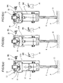
- the movable sleeve 14 is moved downward, as shown in Fig. 2(a) , the cylinder head 13 and the movable sleeve 14 are separated from each other and an upper portion of the combustion chamber 5 is communicated and opened to the atmosphere.
- the contact arm 15 is provided so that it can be freely slid in the vertical direction along the nose portion 6.
- the lower end 15a of the contact arm 15 protrudes from the nose portion 6.
- the contact arm 15 is moved upward relatively with respect to the nose portion 6. Therefore, an upper end portion of the lever 15b extending upward is engaged with the contact switch SW1, so that the contact switch SW1 can be electrically turned on.
- This gas combustion type driving tool includes: a contact switch SW1 turned on and off when the contact arm 15 described above is moved in the vertical direction; a trigger switch SW2 electrically turned on when the trigger lever 16 is pulled; an injection nozzle 18 for injecting fuel gas, which is charged in the gas bomb 17, into the combustion chamber 5; a rotary fan 20 for stirring air in the combustion chamber 5 and forcibly exhausting the combustion gas generated after the combustion; an ignition plug 21 for igniting the mixed gas generated when air in the combustion chamber 5 and fuel gas are stirred by the rotary fan 20; an electric motor mechanism not shown for moving the movable sleeve 14 in the vertical direction; and a control portion 25 for controlling other components.
- the control portion 25 includes MPU having a timer function 26 and a built-in memory 27. According to the control program stored in the built-in memory 27, this MPU judges states of the contact switch SW1 and the trigger switch SW2 and also judges the operation time of the timer 26 (the combustion chamber holding timer 26a, the fan-off timer 26b and the combustion chamber opening timer 26c) and controls the movable sleeve 14, the injection nozzle 18, the rotary fan 20 and the ignition plug 21.
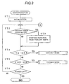
- step ST1 the initialization is executed so that the electric circuit can be initialized (step ST2).
- step ST2 the control portion 25 judges whether or not the fan-off timer 26b is counted up. Since the fan-off timer 26b is reset after the initialization, the programproceeds to step ST4 and the states of the trigger switch SW2 and the contact switch SW1 are checked. When it is in the middle of working, the rotary fan 20 is rotating. Therefore, if it is counted up, the rotary fan 20 is stopped in step ST3 and the fan-off timer 26b is reset and the program proceeds to step ST4.
- step ST4 it is judged by the trigger switch SW2 whether or not the worker pulls the trigger lever.
- the program proceeds to a routine of the contact mode.
- the program proceeds to step ST5.
- the program proceeds to a routine of the trigger mode. Either the contact mode or the trigger mode can be carried out by whether the worker first pulls the trigger lever at the time of starting to drive a nail or the worker first presses the contact arm against the workpiece P.
- step ST101 the fan-off timer 26b is reset and the rotary fan 20 is rotated. Then, the program proceeds to step ST102 so as to move the movable sleeve 14 upward and close the combustion chamber 5. Concerning this matter, refer to Fig. 2(b) .
- the injection nozzle 18 is opened for a predetermined period of time so that the fuel gas can be injected into the combustion chamber 5 which has been closed. Since the rotary fan 20 is rotating at this time, the fuel gas is stirred with air in the combustion chamber 5 and mixed gas is generated. In this way, the preparation for driving nails is completed (step ST103).
- the control portion 25 judges whether the worker executes driving the nails or the worker interrupts driving a nail (step ST104). In the case where the trigger switch SW2 is turned off, it is judged that the nail driving work is interrupted. As shown in Fig. 2(a) , the movable sleeve 14 is moved downward and the combustion chamber 5 is opened (step ST105) so that the mixed gas can be forcibly discharged into the atmosphere. Then the fan-off timer 26b is started and the program is returned to step ST1.
- This fan-off timer 26b is set so that the combustion gas can be completely exhausted.
- a period of time for example, 5 to 10 seconds
- the rotary fan 20 is stopped.
- step ST104 When the trigger switch SW2 is turned on in step ST104, it is judged that a nail driving motion is to be executed. Then, the program proceeds to step ST107 and it is waited that the contact switch SW1 is turned on, that is, it is waited that the worker presses the contact arm 15 against the workpiece P.
- step ST108 When the contact arm 15 is pressed against the workpiece P and the contact switch SW1 is turned on, the oscillating circuit is turned on (step ST108) and the ignition plug 21 is sparked so as to ignite the mixed gas.
- the mixed gas is explosively burned and as shown in Fig. 2(c) , the driving piston 10 is moved downward by the pressure of combustion gas. Therefore, the nail is driven from the nose portion 6 into the workpiece P.
- step ST109 The combustion chamber holding timer 26a is started and it is waited that the combustion chamber 5 is cooled and the pressure in the combustion chamber 5 becomes negative and the driving piston 10 is returned to the initial position.
- the driving piston 10 is moved upward.
- the combustion chamber holding timer 26a counts a period of time (not more than one second, preferably about 0.1 second) (the first period) in which the driving piston 10 is completely returned to the initial position
- the program proceeds to step ST111 and the movable sleeve 14 is moved downward so as to open the combustion chamber 5 and the combustion gas is forcibly exhausted by the rotary fan 20. Concerning this matter, refer to Fig. 6(b) .
- a state of the trigger switch SW2 is judged (step ST112).
- the trigger switch SW2 In the case where the trigger switch SW2 is in a state of being turned on, it is judged that the nail driving motion is continuously executed. Then, the program proceeds to step ST114 and the combustion chamber opening timer 26c is started and it is waited that a predetermined period of time (the second period) is counted up (step ST115). When the second period is counted up, it is judged that the combustion gas is completely discharged from the combustion chamber 5 and replaced with fresh air. Then, the program is returned to step ST102 and the combustion chamber 5 is closed and the fuel gas is injected. Then, it is waited that the contact switch SW1 is turned on. Concerning this matter, refer to Fig. 6(c) .
- step ST112 When the trigger switch SW2 is turned off in step ST112, it is judged that the nail driving is singly executed and the fan-off timer 26b is started and the program is returned to step ST1. Then, the program waits for the next operation in the state of Fig. 2(a) .
- the fan-off timer 26b is reset in step ST201 and the rotary fan 20 is rotated. Then, the program proceeds to step ST202 and the movable sleeve 14 is moved upward so as to close the combustion chamber 5.
- step ST203 the injection nozzle 18 is opened for a predetermined period of time so that the fuel gas can be injected into the combustion chamber 5 which has been closed. Since the rotary fan 20 is rotated at this point of time, the fuel gas is stirred with air in the combustion chamber 5 and the mixed gas is generated. In this way, the preparation for driving a nail is completed. Concerning this matter, refer to Fig. 7(b) .
- the control portion 25 judges whether the worker starts driving the nails or the worker interrupts driving the nails (step ST204).
- the contact switch SW1 is turned off, it is judged that the working is to be interrupted. Therefore, the movable sleeve 14 is moved downward and the combustion chamber 5 is opened (step ST205) so that the mixed gas can be forcibly discharged into the atmosphere.
- the fan-off timer 26b is started and the program is returned to step ST2 and the device waits for the next operation in the state shown in Fig. 7(a) .
- a sufficiently long period of time for exhausting the combustion gas is set on this fan-off timer 26b.
- a period of time for example, 5 to 10 seconds
- the third period which is considered to be sufficiently long for forcibly discharging the combustion gas by the rotary fan 20 so that the combustion gas can be completely exhausted.
- step ST204 When the contact switch SW1 is turned on in ST204, it is judged that the nail driving is to be executed and the program proceeds to step ST207 and it is waited that the trigger switch SW2 is turned on, that is, it is waited that the worker pulls the trigger lever so that a nail can be driven into the workpiece P.
- step ST208 When the trigger lever 16 is pulled and the trigger switch SW2 is turned on, the oscillation circuit is turned on (step ST208) and the ignition plug 21 is sparked and the mixed gas is ignited.
- the mixed gas is explosively burned.
- the driving piston 10 is moved downward by the pressure of combustion gas. Therefore, the nail is driven from the nose portion 6 into the workpiece P.
- step ST209 The combustion chamber holding timer 26a is started and it is waited that the combustion chamber 5 is cooled and the pressure in the combustion chamber 5 becomes negative and the driving piston 10 is returned to the initial position.
- the pressure in the combustion chamber 5 becomes negative as shown in Fig. 8 (a)
- the driving piston 10 is moved upward.
- the combustion chamber holding timer 26a counts a period of time (not more than one second, preferably about 0.1 second) (the first period) in which the driving piston 10 is completely returned to the initial position
- the program proceeds to step ST211 and the movable sleeve 14 is moved downward so as to open the combustion chamber 5 and the combustion gas is forcibly exhausted by the rotary fan 20. Concerning this matter, refer to Fig. 8(b) .
- a state of the contact switch SW1 is judged (step ST212).
- the contact switch SW1 In the case where the contact switch SW1 is in a state of being turned on, it is judged that the nail driving motion is continuously executed in which while the contact arm 15 is being pressed against the workpiece P, the nails are continuously driven by shifting the gas combustion type driving tool, that is, it is judged that a so-called shifting driving is executed.
- the program proceeds to step ST214 and the combustion chamber opening timer 26c is started and it is waited that the timer is counted up (step ST215). After the timer has been counted up, the program returns to step ST202 and the combustion chamber 5 is closed and the fuel gas is injected into the combustion chamber 5. Then, it is waited that the trigger switch SW2 is turned on. Concerning this matter, refer to Fig. 8(c) .
- step ST212 When the contact switch SW1 is turned off in step ST212, it is judged that the nail driving is singly executed. Therefore, the fan-off timer 26b is started and the program is returned to step ST2. Then, the program waits for the next operation in the state shown in Fig. 7(a) .
- the trigger lever 16 is pulled first or even when the contact arm 15 is pressed first against the workpiece, it is possible to make preparations for driving the nail.
- the contact mode when the contact arm 15 is pressed against the workpiece P, the ignition plug 21 is sparked so that the nail can be driven.
- the trigger mode when the trigger lever 16 is pulled, the ignition plug 21 is sparked so that the nail can be driven.
- the driving piston 10 has been moved upward by the negative pressure in the combustion chamber 5
- the combustion chamber 5 is opened, the combustion gas is exhausted, the combustion chamber 5 is closed and the fuel gas is injected, that is, preparations for driving the nail can be automatically made.
- the nails can be continuously driven.
- the contact arm 15 is kept being pressed against the workpiece P after the completion of driving the nail, after the driving piston 10 has been moved upward by the negative pressure in the combustion chamber 5, the combustion chamber 5 is opened, the combustion gas is exhausted, the combustion chamber 5 is closed and the fuel gas is injected, that is, preparations for driving the nail can be automatically made. Therefore, the nails can be continuously driven by the shifting driving in which the nails are successively driven while the gas combustion type driving tool is being shifted on the workpiece P.
- the mode of driving the nails can be freely selected and the nails can be continuously driven by the selected mode. In this way, it is possible to realize a gas combustion type driving tool, the operation property and the working efficiency of which are excellent.
- the present invention can be applied to a gas combustion type driving tool.
Landscapes
- Engineering & Computer Science (AREA)
- Chemical & Material Sciences (AREA)
- Combustion & Propulsion (AREA)
- Mechanical Engineering (AREA)
- Portable Nailing Machines And Staplers (AREA)
- Sampling And Sample Adjustment (AREA)
Applications Claiming Priority (2)
| Application Number | Priority Date | Filing Date | Title |
|---|---|---|---|
| JP2006328290A JP4899840B2 (ja) | 2006-12-05 | 2006-12-05 | ガス燃焼式打込み工具 |
| PCT/JP2007/073420 WO2008069215A1 (ja) | 2006-12-05 | 2007-12-04 | ガス燃焼式打込み工具 |
Publications (3)
| Publication Number | Publication Date |
|---|---|
| EP2090403A1 true EP2090403A1 (de) | 2009-08-19 |
| EP2090403A4 EP2090403A4 (de) | 2011-05-18 |
| EP2090403B1 EP2090403B1 (de) | 2012-04-18 |
Family
ID=39492100
Family Applications (1)
| Application Number | Title | Priority Date | Filing Date |
|---|---|---|---|
| EP07850068A Not-in-force EP2090403B1 (de) | 2006-12-05 | 2007-12-04 | Gasverbrennungskraftbetriebenes eintreibwerkzeug |
Country Status (9)
| Country | Link |
|---|---|
| US (1) | US8006880B2 (de) |
| EP (1) | EP2090403B1 (de) |
| JP (1) | JP4899840B2 (de) |
| CN (1) | CN101547772B (de) |
| AT (1) | ATE553888T1 (de) |
| AU (1) | AU2007329968A1 (de) |
| CA (1) | CA2670057A1 (de) |
| TW (1) | TWI457211B (de) |
| WO (1) | WO2008069215A1 (de) |
Families Citing this family (9)
| Publication number | Priority date | Publication date | Assignee | Title |
|---|---|---|---|---|
| JP5240648B2 (ja) * | 2008-03-12 | 2013-07-17 | 日立工機株式会社 | 燃焼式打込工具 |
| JP2011088269A (ja) * | 2009-09-25 | 2011-05-06 | Makita Corp | 打ち込み工具 |
| JP5429010B2 (ja) * | 2010-04-02 | 2014-02-26 | マックス株式会社 | ガス燃焼式締結機 |
| JP5556496B2 (ja) * | 2010-08-12 | 2014-07-23 | マックス株式会社 | ガス燃焼式打込み工具 |
| JP2013233609A (ja) * | 2012-05-08 | 2013-11-21 | Makita Corp | 打ち込み工具 |
| DE102014206076A1 (de) * | 2014-03-31 | 2015-10-01 | Robert Bosch Gmbh | Handwerkzeugmaschine, Verfahren zum Betreiben |
| EP3181295A1 (de) * | 2015-12-18 | 2017-06-21 | HILTI Aktiengesellschaft | Brenngasbetriebenes eintreibgerät |
| EP3524390B1 (de) * | 2018-01-19 | 2022-03-30 | Max Co., Ltd. | Eintreibgerät |
| US11130221B2 (en) | 2019-01-31 | 2021-09-28 | Milwaukee Electric Tool Corporation | Powered fastener driver |
Family Cites Families (20)
| Publication number | Priority date | Publication date | Assignee | Title |
|---|---|---|---|---|
| US3012549A (en) * | 1957-01-30 | 1961-12-12 | Bard | Internal combustion device |
| US3967771A (en) * | 1974-12-16 | 1976-07-06 | Smith James E | Self-contained impact tool |
| US4403722A (en) * | 1981-01-22 | 1983-09-13 | Signode Corporation | Combustion gas powered fastener driving tool |
| US4483473A (en) * | 1983-05-02 | 1984-11-20 | Signode Corporation | Portable gas-powered fastener driving tool |
| US5263439A (en) * | 1992-11-13 | 1993-11-23 | Illinois Tool Works Inc. | Fuel system for combustion-powered, fastener-driving tool |
| US5415136A (en) * | 1993-08-30 | 1995-05-16 | Illinois Tool Works Inc. | Combined ignition and fuel system for combustion-powered tool |
| US5860580A (en) * | 1996-05-03 | 1999-01-19 | Illinois Tool Works Inc. | Piston retention device for combustion-powered tools |
| CN1273270C (zh) * | 2002-08-09 | 2006-09-06 | 日立工机株式会社 | 以燃气为动力的射钉枪 |
| JP4151346B2 (ja) * | 2002-08-09 | 2008-09-17 | 日立工機株式会社 | 燃焼式打込み工具 |
| JP4055509B2 (ja) * | 2002-08-09 | 2008-03-05 | 日立工機株式会社 | 燃焼式打込み工具 |
| JP3925793B2 (ja) | 2002-08-09 | 2007-06-06 | 日立工機株式会社 | 燃焼式打込み工具 |
| JP4665432B2 (ja) * | 2003-06-20 | 2011-04-06 | 日立工機株式会社 | 燃焼式動力工具 |
| JP4239731B2 (ja) * | 2003-07-04 | 2009-03-18 | マックス株式会社 | 動力駆動釘打機のコンタクト機構 |
| JP4147403B2 (ja) * | 2003-07-31 | 2008-09-10 | マックス株式会社 | ガス燃焼式衝撃工具の燃焼室構造 |
| US7341171B2 (en) * | 2004-02-09 | 2008-03-11 | Illinois Tool Works Inc. | Fan control for combustion-powered fastener-driving tool |
| US7163134B2 (en) * | 2004-02-09 | 2007-01-16 | Illinois Tool Works Inc. | Repetitive cycle tool logic and mode indicator for combustion powered fastener-driving tool |
| JP4353110B2 (ja) * | 2004-04-19 | 2009-10-28 | 日立工機株式会社 | 燃焼式釘打機 |
| JP4923436B2 (ja) * | 2005-05-10 | 2012-04-25 | マックス株式会社 | ガス燃焼式打込み工具 |
| JP4877457B2 (ja) * | 2005-05-17 | 2012-02-15 | マックス株式会社 | ガス燃焼式打込み工具における釘送り作動遅延機構 |
| JP2006328290A (ja) | 2005-05-30 | 2006-12-07 | Mitsubishi Chemicals Corp | 粒状重合体の製造方法、イオン交換樹脂の製造方法、及び合成吸着剤の製造方法、並びにアニオン交換樹脂、カチオン交換樹脂、及び合成吸着剤 |
-
2006
- 2006-12-05 JP JP2006328290A patent/JP4899840B2/ja not_active Expired - Fee Related
-
2007
- 2007-12-04 CA CA002670057A patent/CA2670057A1/en not_active Abandoned
- 2007-12-04 TW TW096146056A patent/TWI457211B/zh not_active IP Right Cessation
- 2007-12-04 US US12/517,647 patent/US8006880B2/en not_active Expired - Fee Related
- 2007-12-04 CN CN2007800451146A patent/CN101547772B/zh not_active Expired - Fee Related
- 2007-12-04 EP EP07850068A patent/EP2090403B1/de not_active Not-in-force
- 2007-12-04 WO PCT/JP2007/073420 patent/WO2008069215A1/ja not_active Ceased
- 2007-12-04 AU AU2007329968A patent/AU2007329968A1/en not_active Abandoned
- 2007-12-04 AT AT07850068T patent/ATE553888T1/de active
Also Published As
| Publication number | Publication date |
|---|---|
| JP4899840B2 (ja) | 2012-03-21 |
| AU2007329968A1 (en) | 2008-06-12 |
| TWI457211B (zh) | 2014-10-21 |
| JP2008137142A (ja) | 2008-06-19 |
| US8006880B2 (en) | 2011-08-30 |
| EP2090403A4 (de) | 2011-05-18 |
| WO2008069215A1 (ja) | 2008-06-12 |
| CN101547772B (zh) | 2013-05-15 |
| ATE553888T1 (de) | 2012-05-15 |
| CN101547772A (zh) | 2009-09-30 |
| TW200836891A (en) | 2008-09-16 |
| US20100032467A1 (en) | 2010-02-11 |
| CA2670057A1 (en) | 2008-06-12 |
| EP2090403B1 (de) | 2012-04-18 |
Similar Documents
| Publication | Publication Date | Title |
|---|---|---|
| EP2090403B1 (de) | Gasverbrennungskraftbetriebenes eintreibwerkzeug | |
| JP4685212B2 (ja) | 燃焼式動力工具 | |
| EP1914041B1 (de) | Gasverbrennungskraftbetriebenes eintreibwerkzeug | |
| EP1459850B1 (de) | Verbrennungskraftbetriebenes Werkzeug mit Vorrichtung zur Vermeidung von Überhitzung der mechanischen Komponenten im Werkzeug | |
| US7163134B2 (en) | Repetitive cycle tool logic and mode indicator for combustion powered fastener-driving tool | |
| US5909836A (en) | Combustion powered tool with combustion chamber lockout | |
| EP2065138B1 (de) | Gasverbrennungsgetriebenes werkzeug | |
| EP2161107B1 (de) | Durch gasverbrennung betriebenes schlagwerkzeug | |
| EP1657028A2 (de) | Verbrennungskraftbetriebenes Werkzeug | |
| EP2380705A1 (de) | Gasverbrennungschlagwerkzeug | |
| US7703648B2 (en) | Gas combustion type driving tool | |
| US8070031B2 (en) | Variable ignition delay for combustion nailer | |
| JP4055509B2 (ja) | 燃焼式打込み工具 | |
| MX2007001283A (es) | Cuchilla impulsora con camara de combustion auxiliar para una herramienta impusora de sujetador accionada por combustion. | |
| US20090152316A1 (en) | Selectable firing mode with electromechanical lockout for combustion-powered fastener -driving tool |
Legal Events
| Date | Code | Title | Description |
|---|---|---|---|
| PUAI | Public reference made under article 153(3) epc to a published international application that has entered the european phase |
Free format text: ORIGINAL CODE: 0009012 |
|
| 17P | Request for examination filed |
Effective date: 20090527 |
|
| AK | Designated contracting states |
Kind code of ref document: A1 Designated state(s): AT BE BG CH CY CZ DE DK EE ES FI FR GB GR HU IE IS IT LI LT LU LV MC MT NL PL PT RO SE SI SK TR |
|
| DAX | Request for extension of the european patent (deleted) | ||
| A4 | Supplementary search report drawn up and despatched |
Effective date: 20110420 |
|
| GRAP | Despatch of communication of intention to grant a patent |
Free format text: ORIGINAL CODE: EPIDOSNIGR1 |
|
| GRAS | Grant fee paid |
Free format text: ORIGINAL CODE: EPIDOSNIGR3 |
|
| GRAA | (expected) grant |
Free format text: ORIGINAL CODE: 0009210 |
|
| AK | Designated contracting states |
Kind code of ref document: B1 Designated state(s): AT BE BG CH CY CZ DE DK EE ES FI FR GB GR HU IE IS IT LI LT LU LV MC MT NL PL PT RO SE SI SK TR |
|
| REG | Reference to a national code |
Ref country code: GB Ref legal event code: FG4D |
|
| REG | Reference to a national code |
Ref country code: CH Ref legal event code: NV Representative=s name: BOVARD AG Ref country code: CH Ref legal event code: EP |
|
| REG | Reference to a national code |
Ref country code: IE Ref legal event code: FG4D |
|
| REG | Reference to a national code |
Ref country code: AT Ref legal event code: REF Ref document number: 553888 Country of ref document: AT Kind code of ref document: T Effective date: 20120515 |
|
| REG | Reference to a national code |
Ref country code: DE Ref legal event code: R096 Ref document number: 602007022161 Country of ref document: DE Effective date: 20120614 |
|
| REG | Reference to a national code |
Ref country code: NL Ref legal event code: VDEP Effective date: 20120418 |
|
| REG | Reference to a national code |
Ref country code: AT Ref legal event code: MK05 Ref document number: 553888 Country of ref document: AT Kind code of ref document: T Effective date: 20120418 |
|
| LTIE | Lt: invalidation of european patent or patent extension |
Effective date: 20120418 |
|
| PG25 | Lapsed in a contracting state [announced via postgrant information from national office to epo] |
Ref country code: PL Free format text: LAPSE BECAUSE OF FAILURE TO SUBMIT A TRANSLATION OF THE DESCRIPTION OR TO PAY THE FEE WITHIN THE PRESCRIBED TIME-LIMIT Effective date: 20120418 Ref country code: CY Free format text: LAPSE BECAUSE OF FAILURE TO SUBMIT A TRANSLATION OF THE DESCRIPTION OR TO PAY THE FEE WITHIN THE PRESCRIBED TIME-LIMIT Effective date: 20120418 Ref country code: SE Free format text: LAPSE BECAUSE OF FAILURE TO SUBMIT A TRANSLATION OF THE DESCRIPTION OR TO PAY THE FEE WITHIN THE PRESCRIBED TIME-LIMIT Effective date: 20120418 Ref country code: LT Free format text: LAPSE BECAUSE OF FAILURE TO SUBMIT A TRANSLATION OF THE DESCRIPTION OR TO PAY THE FEE WITHIN THE PRESCRIBED TIME-LIMIT Effective date: 20120418 Ref country code: FI Free format text: LAPSE BECAUSE OF FAILURE TO SUBMIT A TRANSLATION OF THE DESCRIPTION OR TO PAY THE FEE WITHIN THE PRESCRIBED TIME-LIMIT Effective date: 20120418 Ref country code: IS Free format text: LAPSE BECAUSE OF FAILURE TO SUBMIT A TRANSLATION OF THE DESCRIPTION OR TO PAY THE FEE WITHIN THE PRESCRIBED TIME-LIMIT Effective date: 20120818 |
|
| PG25 | Lapsed in a contracting state [announced via postgrant information from national office to epo] |
Ref country code: PT Free format text: LAPSE BECAUSE OF FAILURE TO SUBMIT A TRANSLATION OF THE DESCRIPTION OR TO PAY THE FEE WITHIN THE PRESCRIBED TIME-LIMIT Effective date: 20120820 Ref country code: SI Free format text: LAPSE BECAUSE OF FAILURE TO SUBMIT A TRANSLATION OF THE DESCRIPTION OR TO PAY THE FEE WITHIN THE PRESCRIBED TIME-LIMIT Effective date: 20120418 Ref country code: GR Free format text: LAPSE BECAUSE OF FAILURE TO SUBMIT A TRANSLATION OF THE DESCRIPTION OR TO PAY THE FEE WITHIN THE PRESCRIBED TIME-LIMIT Effective date: 20120719 Ref country code: LV Free format text: LAPSE BECAUSE OF FAILURE TO SUBMIT A TRANSLATION OF THE DESCRIPTION OR TO PAY THE FEE WITHIN THE PRESCRIBED TIME-LIMIT Effective date: 20120418 |
|
| PG25 | Lapsed in a contracting state [announced via postgrant information from national office to epo] |
Ref country code: BE Free format text: LAPSE BECAUSE OF FAILURE TO SUBMIT A TRANSLATION OF THE DESCRIPTION OR TO PAY THE FEE WITHIN THE PRESCRIBED TIME-LIMIT Effective date: 20120418 |
|
| PG25 | Lapsed in a contracting state [announced via postgrant information from national office to epo] |
Ref country code: CZ Free format text: LAPSE BECAUSE OF FAILURE TO SUBMIT A TRANSLATION OF THE DESCRIPTION OR TO PAY THE FEE WITHIN THE PRESCRIBED TIME-LIMIT Effective date: 20120418 Ref country code: NL Free format text: LAPSE BECAUSE OF FAILURE TO SUBMIT A TRANSLATION OF THE DESCRIPTION OR TO PAY THE FEE WITHIN THE PRESCRIBED TIME-LIMIT Effective date: 20120418 Ref country code: RO Free format text: LAPSE BECAUSE OF FAILURE TO SUBMIT A TRANSLATION OF THE DESCRIPTION OR TO PAY THE FEE WITHIN THE PRESCRIBED TIME-LIMIT Effective date: 20120418 Ref country code: EE Free format text: LAPSE BECAUSE OF FAILURE TO SUBMIT A TRANSLATION OF THE DESCRIPTION OR TO PAY THE FEE WITHIN THE PRESCRIBED TIME-LIMIT Effective date: 20120418 Ref country code: AT Free format text: LAPSE BECAUSE OF FAILURE TO SUBMIT A TRANSLATION OF THE DESCRIPTION OR TO PAY THE FEE WITHIN THE PRESCRIBED TIME-LIMIT Effective date: 20120418 Ref country code: SK Free format text: LAPSE BECAUSE OF FAILURE TO SUBMIT A TRANSLATION OF THE DESCRIPTION OR TO PAY THE FEE WITHIN THE PRESCRIBED TIME-LIMIT Effective date: 20120418 Ref country code: DK Free format text: LAPSE BECAUSE OF FAILURE TO SUBMIT A TRANSLATION OF THE DESCRIPTION OR TO PAY THE FEE WITHIN THE PRESCRIBED TIME-LIMIT Effective date: 20120418 |
|
| PLBE | No opposition filed within time limit |
Free format text: ORIGINAL CODE: 0009261 |
|
| STAA | Information on the status of an ep patent application or granted ep patent |
Free format text: STATUS: NO OPPOSITION FILED WITHIN TIME LIMIT |
|
| PG25 | Lapsed in a contracting state [announced via postgrant information from national office to epo] |
Ref country code: IT Free format text: LAPSE BECAUSE OF FAILURE TO SUBMIT A TRANSLATION OF THE DESCRIPTION OR TO PAY THE FEE WITHIN THE PRESCRIBED TIME-LIMIT Effective date: 20120418 |
|
| 26N | No opposition filed |
Effective date: 20130121 |
|
| PG25 | Lapsed in a contracting state [announced via postgrant information from national office to epo] |
Ref country code: ES Free format text: LAPSE BECAUSE OF FAILURE TO SUBMIT A TRANSLATION OF THE DESCRIPTION OR TO PAY THE FEE WITHIN THE PRESCRIBED TIME-LIMIT Effective date: 20120729 |
|
| REG | Reference to a national code |
Ref country code: DE Ref legal event code: R097 Ref document number: 602007022161 Country of ref document: DE Effective date: 20130121 |
|
| PG25 | Lapsed in a contracting state [announced via postgrant information from national office to epo] |
Ref country code: MC Free format text: LAPSE BECAUSE OF NON-PAYMENT OF DUE FEES Effective date: 20121231 Ref country code: BG Free format text: LAPSE BECAUSE OF FAILURE TO SUBMIT A TRANSLATION OF THE DESCRIPTION OR TO PAY THE FEE WITHIN THE PRESCRIBED TIME-LIMIT Effective date: 20120718 |
|
| GBPC | Gb: european patent ceased through non-payment of renewal fee |
Effective date: 20121204 |
|
| REG | Reference to a national code |
Ref country code: IE Ref legal event code: MM4A |
|
| PG25 | Lapsed in a contracting state [announced via postgrant information from national office to epo] |
Ref country code: IE Free format text: LAPSE BECAUSE OF NON-PAYMENT OF DUE FEES Effective date: 20121204 |
|
| PG25 | Lapsed in a contracting state [announced via postgrant information from national office to epo] |
Ref country code: GB Free format text: LAPSE BECAUSE OF NON-PAYMENT OF DUE FEES Effective date: 20121204 Ref country code: MT Free format text: LAPSE BECAUSE OF FAILURE TO SUBMIT A TRANSLATION OF THE DESCRIPTION OR TO PAY THE FEE WITHIN THE PRESCRIBED TIME-LIMIT Effective date: 20120418 |
|
| PG25 | Lapsed in a contracting state [announced via postgrant information from national office to epo] |
Ref country code: TR Free format text: LAPSE BECAUSE OF FAILURE TO SUBMIT A TRANSLATION OF THE DESCRIPTION OR TO PAY THE FEE WITHIN THE PRESCRIBED TIME-LIMIT Effective date: 20120418 |
|
| PG25 | Lapsed in a contracting state [announced via postgrant information from national office to epo] |
Ref country code: LU Free format text: LAPSE BECAUSE OF NON-PAYMENT OF DUE FEES Effective date: 20121204 |
|
| PG25 | Lapsed in a contracting state [announced via postgrant information from national office to epo] |
Ref country code: HU Free format text: LAPSE BECAUSE OF FAILURE TO SUBMIT A TRANSLATION OF THE DESCRIPTION OR TO PAY THE FEE WITHIN THE PRESCRIBED TIME-LIMIT Effective date: 20071204 |
|
| REG | Reference to a national code |
Ref country code: FR Ref legal event code: PLFP Year of fee payment: 9 |
|
| REG | Reference to a national code |
Ref country code: FR Ref legal event code: PLFP Year of fee payment: 10 |
|
| REG | Reference to a national code |
Ref country code: FR Ref legal event code: PLFP Year of fee payment: 11 |
|
| PGFP | Annual fee paid to national office [announced via postgrant information from national office to epo] |
Ref country code: FR Payment date: 20211109 Year of fee payment: 15 |
|
| PGFP | Annual fee paid to national office [announced via postgrant information from national office to epo] |
Ref country code: CH Payment date: 20211116 Year of fee payment: 15 |
|
| PGFP | Annual fee paid to national office [announced via postgrant information from national office to epo] |
Ref country code: DE Payment date: 20220622 Year of fee payment: 16 |
|
| REG | Reference to a national code |
Ref country code: CH Ref legal event code: PL |
|
| PG25 | Lapsed in a contracting state [announced via postgrant information from national office to epo] |
Ref country code: LI Free format text: LAPSE BECAUSE OF NON-PAYMENT OF DUE FEES Effective date: 20221231 Ref country code: CH Free format text: LAPSE BECAUSE OF NON-PAYMENT OF DUE FEES Effective date: 20221231 |
|
| PG25 | Lapsed in a contracting state [announced via postgrant information from national office to epo] |
Ref country code: FR Free format text: LAPSE BECAUSE OF NON-PAYMENT OF DUE FEES Effective date: 20221231 |
|
| REG | Reference to a national code |
Ref country code: DE Ref legal event code: R119 Ref document number: 602007022161 Country of ref document: DE |
|
| PG25 | Lapsed in a contracting state [announced via postgrant information from national office to epo] |
Ref country code: DE Free format text: LAPSE BECAUSE OF NON-PAYMENT OF DUE FEES Effective date: 20240702 |
|
| PG25 | Lapsed in a contracting state [announced via postgrant information from national office to epo] |
Ref country code: DE Free format text: LAPSE BECAUSE OF NON-PAYMENT OF DUE FEES Effective date: 20240702 |