EP2090415A1 - Procédé de fabrication d'une poutre treillis - Google Patents
Procédé de fabrication d'une poutre treillis Download PDFInfo
- Publication number
- EP2090415A1 EP2090415A1 EP09290113A EP09290113A EP2090415A1 EP 2090415 A1 EP2090415 A1 EP 2090415A1 EP 09290113 A EP09290113 A EP 09290113A EP 09290113 A EP09290113 A EP 09290113A EP 2090415 A1 EP2090415 A1 EP 2090415A1
- Authority
- EP
- European Patent Office
- Prior art keywords
- concrete
- mold
- passive
- reinforcement
- armature
- Prior art date
- Legal status (The legal status is an assumption and is not a legal conclusion. Google has not performed a legal analysis and makes no representation as to the accuracy of the status listed.)
- Granted
Links
Images
Classifications
-
- B—PERFORMING OPERATIONS; TRANSPORTING
- B28—WORKING CEMENT, CLAY, OR STONE
- B28B—SHAPING CLAY OR OTHER CERAMIC COMPOSITIONS; SHAPING SLAG; SHAPING MIXTURES CONTAINING CEMENTITIOUS MATERIAL, e.g. PLASTER
- B28B23/00—Arrangements specially adapted for the production of shaped articles with elements wholly or partly embedded in the moulding material; Production of reinforced objects
- B28B23/02—Arrangements specially adapted for the production of shaped articles with elements wholly or partly embedded in the moulding material; Production of reinforced objects wherein the elements are reinforcing members
- B28B23/04—Arrangements specially adapted for the production of shaped articles with elements wholly or partly embedded in the moulding material; Production of reinforced objects wherein the elements are reinforcing members the elements being stressed
- B28B23/06—Arrangements specially adapted for the production of shaped articles with elements wholly or partly embedded in the moulding material; Production of reinforced objects wherein the elements are reinforcing members the elements being stressed for the production of elongated articles
-
- B—PERFORMING OPERATIONS; TRANSPORTING
- B28—WORKING CEMENT, CLAY, OR STONE
- B28B—SHAPING CLAY OR OTHER CERAMIC COMPOSITIONS; SHAPING SLAG; SHAPING MIXTURES CONTAINING CEMENTITIOUS MATERIAL, e.g. PLASTER
- B28B23/00—Arrangements specially adapted for the production of shaped articles with elements wholly or partly embedded in the moulding material; Production of reinforced objects
- B28B23/0062—Arrangements specially adapted for the production of shaped articles with elements wholly or partly embedded in the moulding material; Production of reinforced objects forcing the elements into the cast material, e.g. hooks into cast concrete
-
- B—PERFORMING OPERATIONS; TRANSPORTING
- B28—WORKING CEMENT, CLAY, OR STONE
- B28B—SHAPING CLAY OR OTHER CERAMIC COMPOSITIONS; SHAPING SLAG; SHAPING MIXTURES CONTAINING CEMENTITIOUS MATERIAL, e.g. PLASTER
- B28B23/00—Arrangements specially adapted for the production of shaped articles with elements wholly or partly embedded in the moulding material; Production of reinforced objects
- B28B23/02—Arrangements specially adapted for the production of shaped articles with elements wholly or partly embedded in the moulding material; Production of reinforced objects wherein the elements are reinforcing members
- B28B23/022—Means for inserting reinforcing members into the mould or for supporting them in the mould
- B28B23/024—Supporting means
Definitions
- the present invention relates to a concrete beam equipped with a wire mesh structure surmounting a generally prestressed concrete heel.
- a truss-girder is conventionally manufactured by molding a concrete heel in a chute previously equipped with prestressing wires or cables stretched in this trough, and metal reinforcements which form the trellis structure surmounting the heel emerging from the surface. free of the concrete bath and divided by end forms.
- the concrete poured into the trough coats the prestressing cables and the base of the truss reinforcement.
- the reinforcements that form the lattice generally comprise three wire rods, which are connected by curved steels in the form of sinusoid. Each bent steel extends between a base spinning steel and the steel spinning top of the lattice.
- the two basic stakes are those that are embedded in the concrete and caught in the heel of the beam.
- the subject of the invention is therefore a method for manufacturing a truss-beam comprising a passive reinforcement in the form of a wire mesh and a prestressed concrete heel, according to which concrete is poured into a mold previously equipped with cables. stretched, and after the pouring of the concrete, the base of the passive reinforcement is immersed in the bath maintaining it in position during the setting of the concrete having previously to the immersion of the passive reinforcement in the bath of concrete, equipped the part of the reinforcement intended to be embedded in the concrete of a set of shims for centering and supporting the armature relative to the inner face of the mold.
- the method of the invention of pouring the concrete before installing the welded mesh projecting from the concrete heel has several advantages.
- the passive reinforcement is not likely to be displaced during casting by liquid concrete and its position in the prestressed heel is much better controlled.
- the passive frame is not soiled by concrete pouring heel.
- the setting and holding operation can be mechanized more easily, which guarantees the accuracy of the implementation and the reproducibility of this accuracy.
- the wedging elements are used to ensure the accuracy of the placement of the reinforcement in the heel of the beam.
- the subject of the invention is also a device for implementing the above method, comprising at least one elongate mold in the form of a trough closed at the end by end formwork traversed by prestressing cables, characterized in that the aforesaid mold is arranged on a support having attachment means along the mold for at least a jumper for clamping the passive armature in a position determined with respect to the walls of the mold.
- Each jumper cooperates with the upper steel wire of the frame by means of a spring support member.
- each passive frame is constituted by sections of stainless steel son shaped to be clipped onto the lower steel rods of the passive frame.
- each of these molds defines an elongated concrete receiving tank 5 which encapsulates prestressing cables, all referenced C, which extend in the volume of the tanks being stretched by unrepresented traction devices provided at each longitudinal end of each cable and carried by a frame or table T which also supports the molds (see figure 4 ).
- the concrete will be chosen so that the coating of the cables before the taking is of good quality. This will be for example a fluid concrete that removes or limits the vibration required when using a more traditional concrete. The vibration can also be implemented with the method of the invention.
- the chutes have a very large longitudinal dimension, which makes it possible to manufacture several prestressed beams along a single group of tensioned cables and to save the tensioning mechanisms and the energy used to create this tension.
- the consecutive beams are defined by end forms such as those shown in FIG. figure 2 . These may be traditional materials such as combs that can be traversed by the cables.
- FIG. 1 and 2 thus illustrate the usual equipment necessary for the manufacture of a prestressed beam.
- a passive reinforcement such as that represented in FIG. figure 3 .
- this passive reinforcement is constituted by three strands in 12,13 and 14 which are joined by two corrugated steel wires 15 and 16, welded by the peaks of their corrugations or in the vicinity thereof, for one, alternately to the wire 12 and the wire 14 and for the other to the wire 13 and to the wire 14.
- the corrugations are substantially sinusoidal and extend in convergent planes on the wire 14 which forms the upper wire of the frame or lattice 11.
- the method generally comprises a vibrating phase of the poured concrete during which the position of the passive reinforcement can be disturbed. This poorly controlled final position can lead to manufacturing defects that disqualify the final product, in particular for excessive deformations.
- the conventional method is improved by several modifications, one concerning its unwinding, the others relating to the apparatus used during manufacture.
- the invention proposes to proceed with the casting of the concrete before the establishment of the structure 11.
- the concrete being in place, still liquid or pasty, taking having not yet taken place, it can be vibrated if necessary.
- the passive reinforcement is then placed by immersing its base, the strands 12 and 13, in the bath and maintaining the reinforcement in a determined position relative to the bath until the complete setting of the concrete.
- the armature is equipped a base in the form of a series of centering wedges and support of its base relative to the wall of each mold.
- These wedges are here in the form of stainless steel wires 17 which are folded to be clipped regularly distributed along the wires 12 and 13 of the reinforcement 11, to center this reinforcement with respect to the walls of the mold both laterally and at the same time. altitude, cooperating with these at the lower corners of the chute (see figure 3 ).
- the figure 4 illustrates an apparatus for ensuring the position of the reinforcements in the tanks of liquid concrete.
- These are jumpers 20, also regularly distributed along the beam (in any case in number at least equal to two, at each end, close to formwork end) which span across a series 1-4 of chutes placed side by side between two fastening members 21,22 secured to the table T.
- These bodies 2 and 22 are in the form of tabs for retaining a first leg 20a of each rider 20 when it bears on the frames 11 and is forced to press them when the rider 20 is forced downward by hooking an end flange 20b under the tab 22.
- the support of the rider 20 on the armatures 11 is achieved by means of V-shaped pieces 23 overlapping the upper wire 14 of each armature.
- Each piece 23 is carried by a cross member 20c of the rider 20 by means of an elastically compressible attachment symbolized by a vertical pin 24 secured to each V-piece 23 and sliding in the cross member 20c and a spring tending to bias downwardly. pawn 24.
- the shims 17 described above are replaced by suspensors, for example wire, which are clipped under the lower threads 12 and 13 and come to rest on the cables C prestressing, including the highest ones in the mold.
- suspensors for example wire
- no point of these wedges is flush with the surface of the heel which may be of interest from the point of view of corrosion.
- the use of stainless steel son is not limiting.
- the shims can be provided in any material, including synthetic, capable of supporting the loads involved in this structure.
Landscapes
- Engineering & Computer Science (AREA)
- Manufacturing & Machinery (AREA)
- Chemical & Material Sciences (AREA)
- Ceramic Engineering (AREA)
- Mechanical Engineering (AREA)
- Manufacturing Of Tubular Articles Or Embedded Moulded Articles (AREA)
Abstract
Description
- La présente invention concerne une poutre en béton équipée d'une structure en treillis métallique surmontant un talon en béton généralement précontraint.
- Une poutre-treillis est classiquement fabriquée par moulage d'un talon en béton dans une goulotte préalablement équipée des fils ou câbles de précontrainte tendus dans cette goulotte, et d'armatures métalliques qui forment la structure en treillis surmontant le talon en émergeant de la surface libre du bain de béton et divisée par des coffrages d'about. Le béton coulé dans la goulotte enrobe les câbles de précontrainte et la base de l'armature en treillis. Pour diminuer les déformations après la prise du béton et le relâchement de la tension des fils de précontrainte, il convient de placer correctement et ces fils et les armatures c'est-à-dire de manière symétrique ou équilibrée par rapport à la fibre neutre du talon de sorte que la précontrainte soit régulièrement répartie autour de cette fibre neutre. Alors que la position des câbles de précontrainte est assez bien maîtrisée, il n'en est pas de même pour les éléments d'armature et notamment ceux qui forment le treillis de la poutre.
- Les armatures qui forment le treillis comprennent généralement des aciers filants au nombre de trois, qui sont reliés par des aciers cintrés en forme de sinusoïde. Chaque acier cintré s'étend entre un acier filant de base et l'acier filant de sommet du treillis. Les deux filants de base sont ceux qui sont noyés dans le béton et pris dans le talon de la poutre.
- On cherche à réduire le plus possible la quantité de béton mise en oeuvre dans le talon. Or plus l'épaisseur de ce dernier est faible et plus l'emplacement des armatures doit être précis. C'est en effet la condition à respecter pour prévenir toute déformation excessive du talon au moment du démoulage.
- Par la présente invention, on se propose de maîtriser la mise en place des armatures et des ferraillages d'une poutre ou poutrelle-treillis avec talon en béton par l'utilisation au cours du procédé de fabrication de moyens simples et faciles à mettre en oeuvre.
- A cet effet, l'invention a donc pour objet un procédé de fabrication d'une poutre-treillis comportant une armature passive en forme de treillis métallique et un talon en béton précontraint, selon lequel on coule du béton dans un moule préalablement équipé de câbles tendus, et après la coulée du béton, on plonge la base de l'armature passive dans le bain en la maintenant en position durant la prise du béton en ayant précédemment à l'immersion de l'armature passive dans le bain de béton, équipé la partie de l'armature destinée à être noyée dans le béton d'un ensemble de cales de centrage et d'appui de l'armature par rapport à la face interne du moule.
- Le procédé de l'invention consistant à couler le béton avant d'installer le treillis soudé qui fait saillie du talon en béton, présente plusieurs avantages. Ainsi, l'armature passive n'est pas susceptible d'être déplacée lors de la coulée par le béton liquide et sa position dans le talon précontraint est beaucoup mieux maîtrisée. En outre, l'armature passive n'est pas souillée par le béton de la coulée du talon. Enfin, l'opération de mise en place et de maintien peut être mécanisée plus facilement, ce qui garantit la précision de la mise en place et la reproductibilité de cette précision.
- Les éléments de calage servent à assurer la précision du placement de l'armature dans le talon de la poutrelle.
- L'invention a également pour deuxième objet un matériel pour mettre en oeuvre le procédé ci-dessus, comprenant au moins un moule allongé en forme de goulotte fermé en extrémité par des coffrages d'about traversés par des câbles de précontrainte, caractérisé en ce que le moule susdit est disposé sur un support présentant des moyens d'accrochage le long du moule pour au moins un cavalier de bridage de l'armature passive en position déterminée par rapport aux parois du moule.
- Cette disposition permet de forcer l'armature passive en position dans le bain de béton jusqu'à la prise de celui-ci. Chaque cavalier coopère avec l'acier filant supérieur de l'armature au moyen d'un organe d'appui à ressort.
- Dans une installation industrielle plusieurs moules goulottes sont côte à côte sur une table support entre lesdits moyens d'accrochage, les cavaliers s'étendant transversalement au-dessus de l'ensemble des moules entre les moyens d'accrochage.
- On notera enfin que les cales d'appui de chaque armature passive sont constituées par des tronçons de fils d'acier inoxydable mis en forme pour pouvoir être clippés sur les filants d'acier inférieurs de l'armature passive.
- D'autres caractéristiques et avantages de l'invention ressortiront de la description d'un exemple de réalisation donnée ci-après à titre d'exemple non limitatif.
- Il sera fait référence aux dessins annexés parmi lesquels :
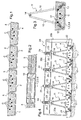
- la
figure 1 est une vue schématique en coupe transversale d'une batterie de quatre moules goulottes de fabrication de poutres ou poutrelles treillis précontraintes, - la
figure 2 est une vue en coupe partielle longitudinale d'un moule, - la
figure 3 illustre par une coupe transversale, une armature passive en forme de treillis métallique, équipée de cales d'appui, - la
figure 4 illustre l'appareil de maintien des armatures passives dans les goulottes de moulage. - Les
figures 1 et 2 illustrent par des vues partielles en coupe, des moules 1,2,3 et 4 en forme de goulottes connus en eux-mêmes pour la réalisation de poutres en béton précontraint. Ainsi, chacun de ces moules définit-il un bac allongé de réception du béton 5 qui vient enrober des câbles de précontrainte, tous référencés par C, qui s'étendent dans le volume des bacs en étant tendus par des dispositifs de traction non représentés prévus à chaque extrémité longitudinale de chaque câble et portés par un bâti ou une table T qui supporte également les moules (voirfigure 4 ). Le béton sera choisi pour que l'enrobage des câbles avant la prise soit de bonne qualité. Ce sera par exemple un béton fluide qui supprime ou limite la vibration nécessaire quand on utilise un béton plus traditionnel. La vibration peut être également mise en oeuvre avec le procédé de l'invention. - Les goulottes ont une très grande dimension longitudinale, ce qui permet de fabriquer plusieurs poutres précontraintes le long d'un seul groupe de câbles tendus et d'économiser les mécanismes tendeurs et l'énergie mise en oeuvre pour créer cette tension. De ce fait, les poutres consécutives sont définies par des coffrages d'about tels que ceux 10 représentés à la
figure 2 . Il peut s'agir de matériels traditionnels tels que des peignes qui peuvent être traversés par les câbles. - Les
figures 1 et 2 illustrent donc le matériel usuel nécessaire à la fabrication d'une poutre précontrainte. Lorsque cette poutre forme le talon d'une poutre treillis, il est ajouté une armature passive telle que celle 11 représentée à lafigure 3 . De manière classique, cette armature passive est constituée par trois filants en acier 12,13 et 14 qui sont réunis par deux fils d'acier ondulés 15 et 16, soudé par les sommets de leurs ondulations ou au voisinage de ceux-ci, pour l'un, alternativement au filant 12 et au filant 14 et pour l'autre au filant 13 et au filant 14. Les ondulations sont sensiblement sinusoïdales et s'étendent dans des plans convergents sur le filant 14 qui forme le filant supérieur de la membrure ou armature en treillis 11. - Selon les procédés connus de fabrication de ce type de poutrelles à treillis, avant de couler le béton, on met et maintient en place tant bien que mal l'armature 11 dans la goulotte de sorte que sa base soit noyée et prise dans le béton après la coulée. Le procédé comporte en général une phase de vibration du béton coulé au cours de laquelle la position de l'armature passive peut-être perturbée. Cette position finale mal contrôlée peut conduire à des défauts de fabrication disqualifiant le produit final notamment pour déformations excessives.
- Selon l'invention, on améliore le procédé classique par plusieurs modifications, les unes concernant son déroulement, les autres étant relatives à l'appareillage employé au cours de la fabrication.
- Pour ce qui concerne le déroulement du procédé de fabrication d'une poutre treillis, l'invention propose de procéder à la coulée du béton avant la mise en place de la structure 11. Le béton étant en place, encore liquide ou pâteux, la prise n'ayant pas encore eu lieu, on peut le vibrer si nécessaire. On procède ensuite à la mise en place de l'armature passive en plongeant sa base, les filants 12 et 13, dans le bain et en maintenant l'armature dans une position déterminée par rapport au bain jusqu'à la prise complète du béton.
- Afin de faciliter le maintien en position correcte de l'armature 11 dans le bain de béton 5, c'est-à-dire par rapport à la goulotte 1,2,3 ou 4, l'armature est équipée d'un piètement en forme d'une série de cales de centrage et d'appui de sa base par rapport à la paroi de chaque moule. Ces cales sont ici en forme de fils d'acier inoxydable 17 qui sont pliés pour être clippés régulièrement répartis le long des filants 12 et 13 de l'armature 11, pour centrer cette armature par rapport aux parois du moule à la fois latéralement et en altitude, en coopérant avec celles-ci au niveau des angles inférieurs de la goulotte (voir
figure 3 ). - La
figure 4 illustre un appareillage pour assurer la position des armatures dans les bacs de béton liquide. Il s'agit de cavaliers 20, également régulièrement répartis le long de la poutrelle (en tout état de cause en nombre au moins égal à deux, à chaque extrémité, proche des coffrages d'about) qui enjambent transversalement une série 1-4 de goulottes placées côte à côte entre deux organes d'accrochage 21,22 solidaires de la table T. Ces organes 2 et 22 sont en forme de pattes pour retenir une première jambe 20a de chaque cavalier 20 lorsque celui-ci prend appui sur les armatures 11 et est contraint d'appuyer sur celles-ci lorsque l'on force vers le bas le cavalier 20 en accrochant une bride d'extrémité 20b sous la patte 22. - L'appui du cavalier 20 sur les armatures 11 est réalisé par l'intermédiaire de pièces 23 en forme de V chevauchant le filant supérieur 14 de chaque armature. Chaque pièce 23 est portée par une traverse 20c du cavalier 20 au moyen d'un attachement élastiquement compressible symbolisé par un pion vertical 24 solidaire de chaque pièce en V 23 et coulissant dans la traverse 20c et un ressort 25 tendant à rappeler vers le bas le pion 24.
- Dans une variante non représentée, les cales 17 décrites ci-dessus sont remplacées par des suspensoirs, par exemple en fil, qui sont clippés sous les filants inférieurs 12 et 13 et qui viennent reposer sur les câbles C de précontrainte, notamment ceux les plus élevés dans la moule. Dans cette variante, aucun point de ces cales n'affleure à la surface du talon ce qui peut présenter un intérêt du point de vue de la corrosion.
- L'usage de fils d'inox n'est pas limitatif. Les cales peuvent être prévues en tout matériau, notamment synthétique, apte à supporter les charges mises en jeu dans cette structure.
- Il sera préférable d'employer un béton fluide pour éviter le vibrage nécessaire à la réalisation d'un bon contact entre les armatures et le béton mais on notera que le procédé de l'invention autorise ce vibrage avant la mise en place des armatures passives et même après cette mise en place du fait de leur calage dans le moule.
Claims (4)
- Procédé de fabrication d'une poutre-treillis comportant une armature passive (11) en forme de treillis métallique et un talon (5) en béton précontraint, selon lequel on coule du béton dans un moule (1,2,3,4) préalablement équipé de câbles (C) tendus, selon lequel, après la coulée du béton on plonge la base (12,13) de l'armature passive (11) dans le bain de béton (5) en la maintenant en position durant la prise du béton, caractérisé en ce que, précédemment à l'immersion de l'armature passive (11) dans le bain de béton (5), on équipe la partie (1,13) de l'armature destinée à être noyée dans le béton (5) d'un ensemble de cales (17) de centrage et d'appui de l'armature (11) par rapport à la face interne du moule (1,2,3,4).
- Matériel pour mettre en oeuvre le procédé selon la revendication 1, comprenant au moins un moule (1, 2, 3, 4) allongé en forme de goulotte, fermé en extrémité par des coffrages (10) d'about traversés par des câbles (C) de précontrainte, caractérisé en ce que le moule susdit est disposé sur un support (T) présentant des moyens d'accrochage (21, 22) le long du moule pour au moins un cavalier (20) de bridage de l'armature passive en position déterminée par rapport aux parois du moule (1,2,3,4).
- Matériel selon la revendication 2, caractérisé en ce que chaque cavalier coopère avec l'acier filant supérieur (14) de l'armature (11) au moyen d'un organe d'appui (23) porté par le cavalier au moyen d'un attachement (24,25) élastiquement.
- Matériel selon l'une des revendications 2 et 3, caractérisé en ce qu'il comprend des cales (17) de centrage et d'appui de chaque armature passive (11) constituées par des tronçons de fils d'acier inoxydable mis en forme pour pouvoir être clippés sur les filants d'acier inférieurs (12,13) de l'armature passive (11).
Priority Applications (1)
| Application Number | Priority Date | Filing Date | Title |
|---|---|---|---|
| PL09290113T PL2090415T3 (pl) | 2008-02-18 | 2009-02-17 | Sposób wytwarzania belki kratowej i sprzętu dostosowanego do jego zastosowania |
Applications Claiming Priority (1)
| Application Number | Priority Date | Filing Date | Title |
|---|---|---|---|
| FR0800851A FR2927565B1 (fr) | 2008-02-18 | 2008-02-18 | Procede de fabrication d'une poutre treillis |
Publications (2)
| Publication Number | Publication Date |
|---|---|
| EP2090415A1 true EP2090415A1 (fr) | 2009-08-19 |
| EP2090415B1 EP2090415B1 (fr) | 2015-01-14 |
Family
ID=39884334
Family Applications (1)
| Application Number | Title | Priority Date | Filing Date |
|---|---|---|---|
| EP09290113.1A Active EP2090415B1 (fr) | 2008-02-18 | 2009-02-17 | Procédé de fabrication d'une poutre treillis et matériel adapté à sa mise en oeuvre |
Country Status (5)
| Country | Link |
|---|---|
| EP (1) | EP2090415B1 (fr) |
| ES (1) | ES2532628T3 (fr) |
| FR (1) | FR2927565B1 (fr) |
| PL (1) | PL2090415T3 (fr) |
| PT (1) | PT2090415E (fr) |
Cited By (5)
| Publication number | Priority date | Publication date | Assignee | Title |
|---|---|---|---|---|
| AU2009201489B2 (en) * | 2008-04-18 | 2014-03-20 | David Allan Burke | A method for the manufacture of concrete panels |
| CN104647587A (zh) * | 2015-02-12 | 2015-05-27 | 河南省公路工程局集团有限公司 | 组合套打式钢结构制梁台座及预制箱梁组合套打方法 |
| EP3241657A1 (fr) * | 2016-05-04 | 2017-11-08 | Fabemi Qualite | Procede de fabrication en serie de poutrelles en beton precontraint a raidisseur pour systeme de plancher a poutrelles et entrevous |
| BE1029851B1 (nl) * | 2021-10-15 | 2023-05-15 | Betonwerken Vets En Zonen Nv | Werkwijze en tafel voor vervaardiging van een betonwelfsel |
| CN121451678A (zh) * | 2026-01-06 | 2026-02-03 | 中南大学 | 预加反弯矩的钢混凝土-钢桁架组合梁结构及其施工方法 |
Families Citing this family (2)
| Publication number | Priority date | Publication date | Assignee | Title |
|---|---|---|---|---|
| CN106182403A (zh) * | 2016-08-29 | 2016-12-07 | 洛阳中冶重工机械有限公司 | 钢筋网笼吊架循环输送系统 |
| CN113172753B (zh) * | 2021-03-17 | 2023-08-08 | 山东联丰新型建材机械有限公司 | 一种防松动人造石板生产网架挂钩框定处理装置 |
Citations (4)
| Publication number | Priority date | Publication date | Assignee | Title |
|---|---|---|---|---|
| US4261544A (en) * | 1979-03-12 | 1981-04-14 | Addison Elvin R | Element locator for concrete |
| WO1983003276A1 (fr) | 1982-03-16 | 1983-09-29 | Koivu, Teuvo | Procede de fabrication d'une dalle composee |
| FR2536696A1 (fr) | 1982-11-26 | 1984-06-01 | Guerin Gabriel | Procede de fabrication de plaques minces moulees avec armature en reseau et inserts partiellement enrobes et installation pour sa mise en oeuvre |
| EP1555100A1 (fr) * | 2004-01-15 | 2005-07-20 | Soprel | Procédé de fabrication de dalles alvéolées en béton précontraint ainsi que dalles obtenues suite à la mise en oeuvre de ce procédé |
-
2008
- 2008-02-18 FR FR0800851A patent/FR2927565B1/fr active Active
-
2009
- 2009-02-17 PT PT09290113T patent/PT2090415E/pt unknown
- 2009-02-17 ES ES09290113.1T patent/ES2532628T3/es active Active
- 2009-02-17 PL PL09290113T patent/PL2090415T3/pl unknown
- 2009-02-17 EP EP09290113.1A patent/EP2090415B1/fr active Active
Patent Citations (4)
| Publication number | Priority date | Publication date | Assignee | Title |
|---|---|---|---|---|
| US4261544A (en) * | 1979-03-12 | 1981-04-14 | Addison Elvin R | Element locator for concrete |
| WO1983003276A1 (fr) | 1982-03-16 | 1983-09-29 | Koivu, Teuvo | Procede de fabrication d'une dalle composee |
| FR2536696A1 (fr) | 1982-11-26 | 1984-06-01 | Guerin Gabriel | Procede de fabrication de plaques minces moulees avec armature en reseau et inserts partiellement enrobes et installation pour sa mise en oeuvre |
| EP1555100A1 (fr) * | 2004-01-15 | 2005-07-20 | Soprel | Procédé de fabrication de dalles alvéolées en béton précontraint ainsi que dalles obtenues suite à la mise en oeuvre de ce procédé |
Cited By (7)
| Publication number | Priority date | Publication date | Assignee | Title |
|---|---|---|---|---|
| AU2009201489B2 (en) * | 2008-04-18 | 2014-03-20 | David Allan Burke | A method for the manufacture of concrete panels |
| CN104647587A (zh) * | 2015-02-12 | 2015-05-27 | 河南省公路工程局集团有限公司 | 组合套打式钢结构制梁台座及预制箱梁组合套打方法 |
| CN104647587B (zh) * | 2015-02-12 | 2017-02-15 | 河南省公路工程局集团有限公司 | 组合套打式钢结构制梁台座及预制箱梁组合套打方法 |
| EP3241657A1 (fr) * | 2016-05-04 | 2017-11-08 | Fabemi Qualite | Procede de fabrication en serie de poutrelles en beton precontraint a raidisseur pour systeme de plancher a poutrelles et entrevous |
| FR3051007A1 (fr) * | 2016-05-04 | 2017-11-10 | Fabemi Qualite | Procede de fabrication en serie de poutrelles en beton precontraint a raidisseur pour systeme de plancher a poutrelles et entrevous |
| BE1029851B1 (nl) * | 2021-10-15 | 2023-05-15 | Betonwerken Vets En Zonen Nv | Werkwijze en tafel voor vervaardiging van een betonwelfsel |
| CN121451678A (zh) * | 2026-01-06 | 2026-02-03 | 中南大学 | 预加反弯矩的钢混凝土-钢桁架组合梁结构及其施工方法 |
Also Published As
| Publication number | Publication date |
|---|---|
| PT2090415E (pt) | 2015-03-30 |
| FR2927565B1 (fr) | 2012-11-16 |
| PL2090415T3 (pl) | 2015-06-30 |
| ES2532628T3 (es) | 2015-03-30 |
| FR2927565A1 (fr) | 2009-08-21 |
| EP2090415B1 (fr) | 2015-01-14 |
Similar Documents
| Publication | Publication Date | Title |
|---|---|---|
| EP2090415B1 (fr) | Procédé de fabrication d'une poutre treillis et matériel adapté à sa mise en oeuvre | |
| FR2465835A1 (fr) | Procede de construction d'un pont a suspentes obliques ou a membrure bridee | |
| CH630436A5 (fr) | Paroi prefabriquee, notamment pour la construction de maisons d'habitation. | |
| KR101826119B1 (ko) | 프리캐스트 코어를 이용한 상부구조물을 가지는 사장교의 시공방법 및 그에 의해 시공되는 사장교 | |
| FR2478704A1 (fr) | Plancher en beton arme a coffrage permanent | |
| EP0054983B1 (fr) | Procédé de fabrication de traverses de chemin de fer en béton et éléments employés à sa mise en oeuvre | |
| FR2610656A1 (fr) | Dispositif pour guider les cables de precontrainte d'un ouvrage de genie civil | |
| FR2578276A1 (fr) | Element de construction en beton, notamment element de plancher, et procede pour sa fabrication | |
| EP0465303B1 (fr) | Perfectionnements aux ponts à haubans et plus particulièrement à leurs pylônes et haubans | |
| EP3175057B1 (fr) | Élément de structure à précontrainte anticipée | |
| EP1555100B1 (fr) | Procédé de fabrication de dalles alvéolées en béton précontraint ainsi que les dalles obtenues suite à la mise en oeuvre de ce procédé | |
| FR2539792A1 (fr) | Procede de construction de structures etanches, telles que des reservoirs | |
| EP1222340B1 (fr) | Coffrage a paroi filtrante | |
| KR102287372B1 (ko) | 재긴장이 가능한 언본디드 pc 강선의 정착구조 및 그 제작방법 | |
| EP2594700B1 (fr) | Câble de structure et procede d'ancrage d'un tel câble | |
| EP2671698B1 (fr) | Banc de fabrication de poutrelles par filage | |
| EP3117054A1 (fr) | Barrette de renfort pour element de structure | |
| FR2848589A1 (fr) | Procede de fabrication de poutres en beton et installation mettant en oeuvre ledit procede | |
| CH447242A (fr) | Traverse pour voie ferrée | |
| FR2851779A1 (fr) | Element prefabrique de construction | |
| FR2903336A1 (fr) | Procede de fabrication d'une dalle nervuree prefabriquee et dalle nervuree obtenue | |
| FR2590606A2 (fr) | Panneau isolant thermique a parois minces en beton pour composants de construction. | |
| JPH0232404B2 (ja) | Keeburunokasetsuhoho | |
| FR1465840A (fr) | Dispositif mécanique mobile de mise sous tension transversale d'armatures, sur banc de préfabrication | |
| FR2672329A1 (fr) | Cale en ciment ou autres materiaux pour le maintien d'armatures de chainage et de boites d'attentes. |
Legal Events
| Date | Code | Title | Description |
|---|---|---|---|
| PUAI | Public reference made under article 153(3) epc to a published international application that has entered the european phase |
Free format text: ORIGINAL CODE: 0009012 |
|
| AK | Designated contracting states |
Kind code of ref document: A1 Designated state(s): AT BE BG CH CY CZ DE DK EE ES FI FR GB GR HR HU IE IS IT LI LT LU LV MC MK MT NL NO PL PT RO SE SI SK TR |
|
| AX | Request for extension of the european patent |
Extension state: AL BA RS |
|
| 17P | Request for examination filed |
Effective date: 20091230 |
|
| 17Q | First examination report despatched |
Effective date: 20100309 |
|
| AKX | Designation fees paid |
Designated state(s): AT BE BG CH CY CZ DE DK EE ES FI FR GB GR HR HU IE IS IT LI LT LU LV MC MK MT NL NO PL PT RO SE SI SK TR |
|
| GRAP | Despatch of communication of intention to grant a patent |
Free format text: ORIGINAL CODE: EPIDOSNIGR1 |
|
| RIC1 | Information provided on ipc code assigned before grant |
Ipc: E04C 5/16 20060101ALI20140812BHEP Ipc: B28B 23/06 20060101ALI20140812BHEP Ipc: B28B 23/02 20060101AFI20140812BHEP Ipc: B28B 23/00 20060101ALI20140812BHEP |
|
| INTG | Intention to grant announced |
Effective date: 20140912 |
|
| GRAS | Grant fee paid |
Free format text: ORIGINAL CODE: EPIDOSNIGR3 |
|
| GRAA | (expected) grant |
Free format text: ORIGINAL CODE: 0009210 |
|
| AK | Designated contracting states |
Kind code of ref document: B1 Designated state(s): AT BE BG CH CY CZ DE DK EE ES FI FR GB GR HR HU IE IS IT LI LT LU LV MC MK MT NL NO PL PT RO SE SI SK TR |
|
| REG | Reference to a national code |
Ref country code: GB Ref legal event code: FG4D Free format text: NOT ENGLISH |
|
| REG | Reference to a national code |
Ref country code: CH Ref legal event code: EP |
|
| REG | Reference to a national code |
Ref country code: IE Ref legal event code: FG4D Free format text: LANGUAGE OF EP DOCUMENT: FRENCH |
|
| REG | Reference to a national code |
Ref country code: AT Ref legal event code: REF Ref document number: 706766 Country of ref document: AT Kind code of ref document: T Effective date: 20150215 |
|
| REG | Reference to a national code |
Ref country code: DE Ref legal event code: R096 Ref document number: 602009028945 Country of ref document: DE Effective date: 20150226 |
|
| REG | Reference to a national code |
Ref country code: ES Ref legal event code: FG2A Ref document number: 2532628 Country of ref document: ES Kind code of ref document: T3 Effective date: 20150330 Ref country code: PT Ref legal event code: SC4A Free format text: AVAILABILITY OF NATIONAL TRANSLATION Effective date: 20150316 |
|
| REG | Reference to a national code |
Ref country code: AT Ref legal event code: MK05 Ref document number: 706766 Country of ref document: AT Kind code of ref document: T Effective date: 20150114 |
|
| REG | Reference to a national code |
Ref country code: LT Ref legal event code: MG4D |
|
| REG | Reference to a national code |
Ref country code: PL Ref legal event code: T3 |
|
| PG25 | Lapsed in a contracting state [announced via postgrant information from national office to epo] |
Ref country code: LT Free format text: LAPSE BECAUSE OF FAILURE TO SUBMIT A TRANSLATION OF THE DESCRIPTION OR TO PAY THE FEE WITHIN THE PRESCRIBED TIME-LIMIT Effective date: 20150114 Ref country code: NO Free format text: LAPSE BECAUSE OF FAILURE TO SUBMIT A TRANSLATION OF THE DESCRIPTION OR TO PAY THE FEE WITHIN THE PRESCRIBED TIME-LIMIT Effective date: 20150414 Ref country code: BG Free format text: LAPSE BECAUSE OF FAILURE TO SUBMIT A TRANSLATION OF THE DESCRIPTION OR TO PAY THE FEE WITHIN THE PRESCRIBED TIME-LIMIT Effective date: 20150414 Ref country code: FI Free format text: LAPSE BECAUSE OF FAILURE TO SUBMIT A TRANSLATION OF THE DESCRIPTION OR TO PAY THE FEE WITHIN THE PRESCRIBED TIME-LIMIT Effective date: 20150114 Ref country code: HR Free format text: LAPSE BECAUSE OF FAILURE TO SUBMIT A TRANSLATION OF THE DESCRIPTION OR TO PAY THE FEE WITHIN THE PRESCRIBED TIME-LIMIT Effective date: 20150114 Ref country code: SE Free format text: LAPSE BECAUSE OF FAILURE TO SUBMIT A TRANSLATION OF THE DESCRIPTION OR TO PAY THE FEE WITHIN THE PRESCRIBED TIME-LIMIT Effective date: 20150114 |
|
| PG25 | Lapsed in a contracting state [announced via postgrant information from national office to epo] |
Ref country code: LV Free format text: LAPSE BECAUSE OF FAILURE TO SUBMIT A TRANSLATION OF THE DESCRIPTION OR TO PAY THE FEE WITHIN THE PRESCRIBED TIME-LIMIT Effective date: 20150114 Ref country code: AT Free format text: LAPSE BECAUSE OF FAILURE TO SUBMIT A TRANSLATION OF THE DESCRIPTION OR TO PAY THE FEE WITHIN THE PRESCRIBED TIME-LIMIT Effective date: 20150114 Ref country code: IS Free format text: LAPSE BECAUSE OF FAILURE TO SUBMIT A TRANSLATION OF THE DESCRIPTION OR TO PAY THE FEE WITHIN THE PRESCRIBED TIME-LIMIT Effective date: 20150514 Ref country code: GR Free format text: LAPSE BECAUSE OF FAILURE TO SUBMIT A TRANSLATION OF THE DESCRIPTION OR TO PAY THE FEE WITHIN THE PRESCRIBED TIME-LIMIT Effective date: 20150415 |
|
| REG | Reference to a national code |
Ref country code: DE Ref legal event code: R119 Ref document number: 602009028945 Country of ref document: DE |
|
| REG | Reference to a national code |
Ref country code: CH Ref legal event code: PL |
|
| PG25 | Lapsed in a contracting state [announced via postgrant information from national office to epo] |
Ref country code: LI Free format text: LAPSE BECAUSE OF NON-PAYMENT OF DUE FEES Effective date: 20150228 Ref country code: MC Free format text: LAPSE BECAUSE OF FAILURE TO SUBMIT A TRANSLATION OF THE DESCRIPTION OR TO PAY THE FEE WITHIN THE PRESCRIBED TIME-LIMIT Effective date: 20150114 Ref country code: RO Free format text: LAPSE BECAUSE OF FAILURE TO SUBMIT A TRANSLATION OF THE DESCRIPTION OR TO PAY THE FEE WITHIN THE PRESCRIBED TIME-LIMIT Effective date: 20150114 Ref country code: CZ Free format text: LAPSE BECAUSE OF FAILURE TO SUBMIT A TRANSLATION OF THE DESCRIPTION OR TO PAY THE FEE WITHIN THE PRESCRIBED TIME-LIMIT Effective date: 20150114 Ref country code: EE Free format text: LAPSE BECAUSE OF FAILURE TO SUBMIT A TRANSLATION OF THE DESCRIPTION OR TO PAY THE FEE WITHIN THE PRESCRIBED TIME-LIMIT Effective date: 20150114 Ref country code: DK Free format text: LAPSE BECAUSE OF FAILURE TO SUBMIT A TRANSLATION OF THE DESCRIPTION OR TO PAY THE FEE WITHIN THE PRESCRIBED TIME-LIMIT Effective date: 20150114 Ref country code: SK Free format text: LAPSE BECAUSE OF FAILURE TO SUBMIT A TRANSLATION OF THE DESCRIPTION OR TO PAY THE FEE WITHIN THE PRESCRIBED TIME-LIMIT Effective date: 20150114 Ref country code: CH Free format text: LAPSE BECAUSE OF NON-PAYMENT OF DUE FEES Effective date: 20150228 |
|
| REG | Reference to a national code |
Ref country code: IE Ref legal event code: MM4A |
|
| PLBE | No opposition filed within time limit |
Free format text: ORIGINAL CODE: 0009261 |
|
| STAA | Information on the status of an ep patent application or granted ep patent |
Free format text: STATUS: NO OPPOSITION FILED WITHIN TIME LIMIT |
|
| REG | Reference to a national code |
Ref country code: FR Ref legal event code: ST Effective date: 20151030 |
|
| 26N | No opposition filed |
Effective date: 20151015 |
|
| REG | Reference to a national code |
Ref country code: FR Ref legal event code: PLFP Year of fee payment: 8 |
|
| PG25 | Lapsed in a contracting state [announced via postgrant information from national office to epo] |
Ref country code: DE Free format text: LAPSE BECAUSE OF NON-PAYMENT OF DUE FEES Effective date: 20150901 Ref country code: IE Free format text: LAPSE BECAUSE OF NON-PAYMENT OF DUE FEES Effective date: 20150217 |
|
| REG | Reference to a national code |
Ref country code: FR Ref legal event code: RN Effective date: 20160126 |
|
| PG25 | Lapsed in a contracting state [announced via postgrant information from national office to epo] |
Ref country code: FR Free format text: LAPSE BECAUSE OF NON-PAYMENT OF DUE FEES Effective date: 20150316 Ref country code: SI Free format text: LAPSE BECAUSE OF FAILURE TO SUBMIT A TRANSLATION OF THE DESCRIPTION OR TO PAY THE FEE WITHIN THE PRESCRIBED TIME-LIMIT Effective date: 20150114 |
|
| REG | Reference to a national code |
Ref country code: FR Ref legal event code: FC Effective date: 20160304 |
|
| PGRI | Patent reinstated in contracting state [announced from national office to epo] |
Ref country code: FR Effective date: 20160307 |
|
| PG25 | Lapsed in a contracting state [announced via postgrant information from national office to epo] |
Ref country code: MT Free format text: LAPSE BECAUSE OF FAILURE TO SUBMIT A TRANSLATION OF THE DESCRIPTION OR TO PAY THE FEE WITHIN THE PRESCRIBED TIME-LIMIT Effective date: 20150114 |
|
| REG | Reference to a national code |
Ref country code: FR Ref legal event code: PLFP Year of fee payment: 9 |
|
| PG25 | Lapsed in a contracting state [announced via postgrant information from national office to epo] |
Ref country code: HU Free format text: LAPSE BECAUSE OF FAILURE TO SUBMIT A TRANSLATION OF THE DESCRIPTION OR TO PAY THE FEE WITHIN THE PRESCRIBED TIME-LIMIT; INVALID AB INITIO Effective date: 20090217 |
|
| PG25 | Lapsed in a contracting state [announced via postgrant information from national office to epo] |
Ref country code: CY Free format text: LAPSE BECAUSE OF FAILURE TO SUBMIT A TRANSLATION OF THE DESCRIPTION OR TO PAY THE FEE WITHIN THE PRESCRIBED TIME-LIMIT Effective date: 20150114 |
|
| PG25 | Lapsed in a contracting state [announced via postgrant information from national office to epo] |
Ref country code: TR Free format text: LAPSE BECAUSE OF FAILURE TO SUBMIT A TRANSLATION OF THE DESCRIPTION OR TO PAY THE FEE WITHIN THE PRESCRIBED TIME-LIMIT Effective date: 20150114 |
|
| REG | Reference to a national code |
Ref country code: FR Ref legal event code: PLFP Year of fee payment: 10 |
|
| PG25 | Lapsed in a contracting state [announced via postgrant information from national office to epo] |
Ref country code: MK Free format text: LAPSE BECAUSE OF FAILURE TO SUBMIT A TRANSLATION OF THE DESCRIPTION OR TO PAY THE FEE WITHIN THE PRESCRIBED TIME-LIMIT Effective date: 20150114 |
|
| PGFP | Annual fee paid to national office [announced via postgrant information from national office to epo] |
Ref country code: GB Payment date: 20220223 Year of fee payment: 14 |
|
| PGFP | Annual fee paid to national office [announced via postgrant information from national office to epo] |
Ref country code: PT Payment date: 20220203 Year of fee payment: 14 Ref country code: PL Payment date: 20220203 Year of fee payment: 14 Ref country code: NL Payment date: 20220216 Year of fee payment: 14 Ref country code: LU Payment date: 20220216 Year of fee payment: 14 Ref country code: IT Payment date: 20220218 Year of fee payment: 14 Ref country code: BE Payment date: 20220216 Year of fee payment: 14 |
|
| PGFP | Annual fee paid to national office [announced via postgrant information from national office to epo] |
Ref country code: ES Payment date: 20220426 Year of fee payment: 14 |
|
| P01 | Opt-out of the competence of the unified patent court (upc) registered |
Effective date: 20230601 |
|
| REG | Reference to a national code |
Ref country code: NL Ref legal event code: MM Effective date: 20230301 |
|
| REG | Reference to a national code |
Ref country code: BE Ref legal event code: MM Effective date: 20230228 |
|
| GBPC | Gb: european patent ceased through non-payment of renewal fee |
Effective date: 20230217 |
|
| PG25 | Lapsed in a contracting state [announced via postgrant information from national office to epo] |
Ref country code: PT Free format text: LAPSE BECAUSE OF NON-PAYMENT OF DUE FEES Effective date: 20230817 Ref country code: LU Free format text: LAPSE BECAUSE OF NON-PAYMENT OF DUE FEES Effective date: 20230217 |
|
| PG25 | Lapsed in a contracting state [announced via postgrant information from national office to epo] |
Ref country code: NL Free format text: LAPSE BECAUSE OF NON-PAYMENT OF DUE FEES Effective date: 20230301 |
|
| PG25 | Lapsed in a contracting state [announced via postgrant information from national office to epo] |
Ref country code: GB Free format text: LAPSE BECAUSE OF NON-PAYMENT OF DUE FEES Effective date: 20230217 |
|
| PG25 | Lapsed in a contracting state [announced via postgrant information from national office to epo] |
Ref country code: IT Free format text: LAPSE BECAUSE OF NON-PAYMENT OF DUE FEES Effective date: 20230217 Ref country code: GB Free format text: LAPSE BECAUSE OF NON-PAYMENT OF DUE FEES Effective date: 20230217 |
|
| PG25 | Lapsed in a contracting state [announced via postgrant information from national office to epo] |
Ref country code: BE Free format text: LAPSE BECAUSE OF NON-PAYMENT OF DUE FEES Effective date: 20230228 |
|
| REG | Reference to a national code |
Ref country code: ES Ref legal event code: FD2A Effective date: 20240405 |
|
| PG25 | Lapsed in a contracting state [announced via postgrant information from national office to epo] |
Ref country code: ES Free format text: LAPSE BECAUSE OF NON-PAYMENT OF DUE FEES Effective date: 20230218 |
|
| PG25 | Lapsed in a contracting state [announced via postgrant information from national office to epo] |
Ref country code: ES Free format text: LAPSE BECAUSE OF NON-PAYMENT OF DUE FEES Effective date: 20230218 |
|
| PG25 | Lapsed in a contracting state [announced via postgrant information from national office to epo] |
Ref country code: PL Free format text: LAPSE BECAUSE OF NON-PAYMENT OF DUE FEES Effective date: 20230217 |
|
| PG25 | Lapsed in a contracting state [announced via postgrant information from national office to epo] |
Ref country code: PL Free format text: LAPSE BECAUSE OF NON-PAYMENT OF DUE FEES Effective date: 20230217 |
|
| PGFP | Annual fee paid to national office [announced via postgrant information from national office to epo] |
Ref country code: FR Payment date: 20250221 Year of fee payment: 17 |