EP2090439B1 - Eigenständiges tintenstrahldruckmodul - Google Patents
Eigenständiges tintenstrahldruckmodul Download PDFInfo
- Publication number
- EP2090439B1 EP2090439B1 EP07858257A EP07858257A EP2090439B1 EP 2090439 B1 EP2090439 B1 EP 2090439B1 EP 07858257 A EP07858257 A EP 07858257A EP 07858257 A EP07858257 A EP 07858257A EP 2090439 B1 EP2090439 B1 EP 2090439B1
- Authority
- EP
- European Patent Office
- Prior art keywords
- ink
- reservoir
- self
- electrovalve
- inkjet printing
- Prior art date
- Legal status (The legal status is an assumption and is not a legal conclusion. Google has not performed a legal analysis and makes no representation as to the accuracy of the status listed.)
- Not-in-force
Links
- 238000007641 inkjet printing Methods 0.000 title claims description 13
- 239000000976 ink Substances 0.000 claims description 101
- 238000007639 printing Methods 0.000 claims description 21
- 238000004140 cleaning Methods 0.000 claims description 13
- 230000002745 absorbent Effects 0.000 claims description 12
- 239000002250 absorbent Substances 0.000 claims description 12
- 230000002572 peristaltic effect Effects 0.000 claims description 7
- 239000002184 metal Substances 0.000 claims description 6
- 230000003750 conditioning effect Effects 0.000 claims description 4
- 238000006073 displacement reaction Methods 0.000 claims description 3
- 238000001035 drying Methods 0.000 claims description 3
- 239000007788 liquid Substances 0.000 claims description 3
- 238000012423 maintenance Methods 0.000 claims description 3
- 230000007246 mechanism Effects 0.000 claims description 3
- 230000037452 priming Effects 0.000 description 10
- 238000000034 method Methods 0.000 description 5
- 230000008569 process Effects 0.000 description 5
- 239000003086 colorant Substances 0.000 description 4
- 238000010586 diagram Methods 0.000 description 4
- 238000001704 evaporation Methods 0.000 description 3
- 230000008020 evaporation Effects 0.000 description 3
- 230000005499 meniscus Effects 0.000 description 3
- 230000009471 action Effects 0.000 description 2
- 238000010276 construction Methods 0.000 description 2
- 229920001971 elastomer Polymers 0.000 description 2
- 239000000806 elastomer Substances 0.000 description 2
- 238000010408 sweeping Methods 0.000 description 2
- 230000004075 alteration Effects 0.000 description 1
- 238000007664 blowing Methods 0.000 description 1
- 230000003749 cleanliness Effects 0.000 description 1
- 238000000151 deposition Methods 0.000 description 1
- 239000000428 dust Substances 0.000 description 1
- 230000003628 erosive effect Effects 0.000 description 1
- 238000009434 installation Methods 0.000 description 1
- 235000015250 liver sausages Nutrition 0.000 description 1
- 230000010355 oscillation Effects 0.000 description 1
- 230000000630 rising effect Effects 0.000 description 1
- 238000007790 scraping Methods 0.000 description 1
- 238000007789 sealing Methods 0.000 description 1
- 238000000926 separation method Methods 0.000 description 1
- XLYOFNOQVPJJNP-UHFFFAOYSA-N water Substances O XLYOFNOQVPJJNP-UHFFFAOYSA-N 0.000 description 1
Images



Classifications
-
- B—PERFORMING OPERATIONS; TRANSPORTING
- B41—PRINTING; LINING MACHINES; TYPEWRITERS; STAMPS
- B41J—TYPEWRITERS; SELECTIVE PRINTING MECHANISMS, i.e. MECHANISMS PRINTING OTHERWISE THAN FROM A FORME; CORRECTION OF TYPOGRAPHICAL ERRORS
- B41J2/00—Typewriters or selective printing mechanisms characterised by the printing or marking process for which they are designed
- B41J2/005—Typewriters or selective printing mechanisms characterised by the printing or marking process for which they are designed characterised by bringing liquid or particles selectively into contact with a printing material
- B41J2/01—Ink jet
- B41J2/135—Nozzles
- B41J2/145—Arrangement thereof
-
- B—PERFORMING OPERATIONS; TRANSPORTING
- B41—PRINTING; LINING MACHINES; TYPEWRITERS; STAMPS
- B41J—TYPEWRITERS; SELECTIVE PRINTING MECHANISMS, i.e. MECHANISMS PRINTING OTHERWISE THAN FROM A FORME; CORRECTION OF TYPOGRAPHICAL ERRORS
- B41J2/00—Typewriters or selective printing mechanisms characterised by the printing or marking process for which they are designed
- B41J2/005—Typewriters or selective printing mechanisms characterised by the printing or marking process for which they are designed characterised by bringing liquid or particles selectively into contact with a printing material
- B41J2/01—Ink jet
- B41J2/135—Nozzles
- B41J2/145—Arrangement thereof
- B41J2/155—Arrangement thereof for line printing
-
- B—PERFORMING OPERATIONS; TRANSPORTING
- B41—PRINTING; LINING MACHINES; TYPEWRITERS; STAMPS
- B41J—TYPEWRITERS; SELECTIVE PRINTING MECHANISMS, i.e. MECHANISMS PRINTING OTHERWISE THAN FROM A FORME; CORRECTION OF TYPOGRAPHICAL ERRORS
- B41J2/00—Typewriters or selective printing mechanisms characterised by the printing or marking process for which they are designed
- B41J2/005—Typewriters or selective printing mechanisms characterised by the printing or marking process for which they are designed characterised by bringing liquid or particles selectively into contact with a printing material
- B41J2/01—Ink jet
- B41J2/135—Nozzles
- B41J2/165—Prevention or detection of nozzle clogging, e.g. cleaning, capping or moistening for nozzles
- B41J2/16585—Prevention or detection of nozzle clogging, e.g. cleaning, capping or moistening for nozzles for paper-width or non-reciprocating print heads
-
- B—PERFORMING OPERATIONS; TRANSPORTING
- B41—PRINTING; LINING MACHINES; TYPEWRITERS; STAMPS
- B41J—TYPEWRITERS; SELECTIVE PRINTING MECHANISMS, i.e. MECHANISMS PRINTING OTHERWISE THAN FROM A FORME; CORRECTION OF TYPOGRAPHICAL ERRORS
- B41J2/00—Typewriters or selective printing mechanisms characterised by the printing or marking process for which they are designed
- B41J2/005—Typewriters or selective printing mechanisms characterised by the printing or marking process for which they are designed characterised by bringing liquid or particles selectively into contact with a printing material
- B41J2/01—Ink jet
- B41J2/17—Ink jet characterised by ink handling
- B41J2/175—Ink supply systems ; Circuit parts therefor
-
- B—PERFORMING OPERATIONS; TRANSPORTING
- B41—PRINTING; LINING MACHINES; TYPEWRITERS; STAMPS
- B41J—TYPEWRITERS; SELECTIVE PRINTING MECHANISMS, i.e. MECHANISMS PRINTING OTHERWISE THAN FROM A FORME; CORRECTION OF TYPOGRAPHICAL ERRORS
- B41J2/00—Typewriters or selective printing mechanisms characterised by the printing or marking process for which they are designed
- B41J2/005—Typewriters or selective printing mechanisms characterised by the printing or marking process for which they are designed characterised by bringing liquid or particles selectively into contact with a printing material
- B41J2/01—Ink jet
- B41J2/17—Ink jet characterised by ink handling
- B41J2/175—Ink supply systems ; Circuit parts therefor
- B41J2/17596—Ink pumps, ink valves
-
- B—PERFORMING OPERATIONS; TRANSPORTING
- B41—PRINTING; LINING MACHINES; TYPEWRITERS; STAMPS
- B41J—TYPEWRITERS; SELECTIVE PRINTING MECHANISMS, i.e. MECHANISMS PRINTING OTHERWISE THAN FROM A FORME; CORRECTION OF TYPOGRAPHICAL ERRORS
- B41J2202/00—Embodiments of or processes related to ink-jet or thermal heads
- B41J2202/01—Embodiments of or processes related to ink-jet heads
- B41J2202/08—Embodiments of or processes related to ink-jet heads dealing with thermal variations, e.g. cooling
-
- B—PERFORMING OPERATIONS; TRANSPORTING
- B41—PRINTING; LINING MACHINES; TYPEWRITERS; STAMPS
- B41J—TYPEWRITERS; SELECTIVE PRINTING MECHANISMS, i.e. MECHANISMS PRINTING OTHERWISE THAN FROM A FORME; CORRECTION OF TYPOGRAPHICAL ERRORS
- B41J2202/00—Embodiments of or processes related to ink-jet or thermal heads
- B41J2202/01—Embodiments of or processes related to ink-jet heads
- B41J2202/19—Assembling head units
-
- B—PERFORMING OPERATIONS; TRANSPORTING
- B41—PRINTING; LINING MACHINES; TYPEWRITERS; STAMPS
- B41J—TYPEWRITERS; SELECTIVE PRINTING MECHANISMS, i.e. MECHANISMS PRINTING OTHERWISE THAN FROM A FORME; CORRECTION OF TYPOGRAPHICAL ERRORS
- B41J2202/00—Embodiments of or processes related to ink-jet or thermal heads
- B41J2202/01—Embodiments of or processes related to ink-jet heads
- B41J2202/20—Modules
Definitions
- the present invention relates to a self-contained inkjet printing module which has been specially conceived for the construction of inkjet printers in which different print heads are assembled until the desired printing width and number of colours is obtained.
- the number of injectors for each head is usually a power of two (one, two, four, eight, sixteen, thirty-two, sixty-four, one hundred and twenty-eight, etc.), being aligned and distributed uniformly in a plane commonly known as the "Injector plate”.
- This arrangement has to be repeated for each of the different inks (colours) used, In such a way that the heads are arranged ordered in different rows.
- Each of the said heads needs a system that will keep the plate, where the injector holes are housed, in an optimum state of cleanliness so that the quality of the printing is not affected.
- Inkjet print heads normally function by keeping the ink at a pressure below ambient, with the ink being maintained in the Injectors by the action of the meniscus formed due to the surface tension of the ink.
- the meniscus of one or more injectors breaks due to sudden mechanical and/or hydraulic oscillations. This causes the affected injector or injectors to suck in air and become dry.
- the pressure of the ink is normally made to be greater than the outside, so that a small quantity of ink can flow which fills the entire path as far as reaching the injector hole. Increasing the pressure of the ink and/or reducing the external pressure by means of a vacuum carries out this increase in pressure.
- the injector plate After carrying the re-priming as described, the injector plate is flooded and has to be cleaned as we have already mentioned in the previous point.
- the ink flows through the injector holes in such a way that the ink in the injectors is always being renewed and maintains its properties even in the event of containing a highly volatile component, whose evaporation could produce an alteration in its properties.
- the main problem that can appear is that the evaporation of a volatile component and the consequence increase in the concentration of the other components can cause the viscosity of the ink to increase so much that it blocks up the injectors.
- EP-A-870 622 discloses a full width inkjet device which has printhead modules mounted along the length of a support bar.
- the support bar has a channel formed within which extends along its entire length. Water is circulated through the channel in order to control the temperature of the printhead modules.
- the self-contained inkjet printing module which the invention proposes comprises inkjet print heads arranged for printing the width that is required in a single passage.
- This module comprises the maintenance system for the Installed heads, as well as the pressurisation and thermal conditioning system for the ink used. Since this module includes all the elements related to the conditioning of the heads and the ink that they use, the construction of a machine is limited to the installation of as many self-contained modules as might be needed depending on the number of inks and the desired print resolution.
- the self-contained module proposed by the invention offers a basic structure defined by an extruded or machined metal inverted T-section profile In which are incorporated mounted the print heads, with the injector plate being left exposed via the lower part.
- This metal T-section profile includes three cylindrical perforations along its entire length, two of which are located in the lower part and are connected to each other to define a circuit which the liquid has to pass through at the temperature it is wished for the printing module to be functioning at, and the other perforation is arranged in the upper part, the three perforations being horizontal and the latter one defining a collector duct or distributor duct and thermal conditioner for the ink, from which there start a series of as many vertical holes as there are heads that are going to be installed, in such a way that manual valves and tubes can be arranged that supply the ink to the print heads at the desired temperature.
- the head uses the ink, It becomes necessary to refill the working reservoir in order to keep the level within the limits set by the manufacturers of the heads.
- the electrovalves for connecting the reservoir with the outside and for the entrance of Ink under pressure remain open, with the one for the entrance of air under pressure being closed, so that the ink thus flows inside the reservoir without affecting the pressure of the ink in the heads.
- the electrovalves for connecting with the outside air and for the entrance of ink under pressure remain closed, and the one for the entrance of air under pressure is opened, so that this pressure can cause the ink to flow through the injector holes.
- the electrovalve for the ink under pressure is opened and the ink flows inside the reservoir without affecting the pressure of the ink in the heads due to the fact that the reservoir is connected to the outside.
- the electrovalve in bypass with the pump is closed and the peristaltic pump is started up so that the pressure of the air causes the ink to flow through the injector holes.
- This system allows the refilling of the working reservoir to be able to be carried out at the same as the draining is being done.
- the electrovalve for the ink under pressure is opened so that the ink flows inside the reservoir without affecting the pressure of the ink in the heads due to the fact that the reservoir is connected to the outside.
- the centrifugal pump When it is required to increase the pressure for draining and priming, the centrifugal pump is started up so that the pressure of the air causes the ink to flow through the injector holes.
- This system also allows the refilling of the working reservoir to be able to be carried out at the same as the draining is being done.
- the self-contained inkjet printing module furthermore includes a mechanism that is capable of covering the injector plate and being able to collect the ink poured during each draining operation and leave the injector plate as clean as possible In order to be able to print with good quality.
- This mechanism is also capable of preventing the ink from drying when the module is not functioning.
- the invention provides two solutions for the piece that covers the Injector plate, with one solution or the other being used depending on the ink:
- the injector plate is left entirely exposed and it is the concave cover which houses separate absorbent sponges at the ends of its cavity, which collect the surplus ink and clean a movable spatula at the end of each travel, as we will see later on in relation to the figures.
- FIG 3 can be seen the basic structure of the printing module, referenced in general with the number 3 and materialized by the extruded or machined metal inverted T-section profile 4, provided with windows for fitting the print heads 5 with their injector plates 1.
- Reference 6 designates two of the three horizontal longitudinal perforations, the lowest ones, which are connected together with the step 7 at one end, for the circulation of liquid at the desired temperature.
- the ink is supplied to the heads 5 at the correct pressure, from the reservoir 12 in which the level is kept at a certain height 13 with respect to the injector plates 1, arriving at the distributor 8.
- the reference 14 designates the entrance of air at a pressure controlled by the electrovalve 15 and the reference 16 is the entrance of Ink under pressure when the electrovalve 17 is open.
- the electrovalves 15 and 17 are closed and the electrovalve 18 is open, which connects to the outside line 19.
- the pressure with which the ink arrives at the heads via the distributor depends solely on the level In the reservoir 12.
- the electrovalves 18 and 17 remain open during the refilling operation and 15 is closed so that the ink flows inside the reservoir without affecting the pressure of the ink in the heads.
- the electrovalves 18 and 17 remain closed and 15 is open.
- ink under pressure arrives at the reservoir 12 from the duct 16 via the electrovalve 17.
- the electrovalve 20 is fitted in bypass with the peristaltic pump 21.
- the electrovalve 17 remains closed, the electrovalve 2 is open and the peristaltic pump 21 is shut off.
- the pressure of the ink in the heads depends solely on the level inside the working reservoir 12.
- the electrovalve 17 is open so that the ink can flow inside the reservoir without affecting the pressure of the ink in the heads due to the connection duct 19 for the reservoir with the atmosphere.
- the electrovalve 20 When the pressure is increased in order to carry out the draining and priming, the electrovalve 20 is closed and the peristaltic pump 21 is started up, with the ink flowing through the injector orifices.
- the electrovalve 17 is opened so that the ink flows inside the reservoir 12 since it is connected to the outside via the duct 19.
- the centrifugal pump 22 When it is required to increase the pressure in order to carry out draining and priming, the centrifugal pump 22 is started up. This system also allows refilling simultaneous with draining.
- the reference 26 designates the concave cover with another absorbent sponge 27 which collects the surplus ink.
- the cover 26 moves to position b) of figure 7 and after the draining the surplus ink is sucked up via the duct 28, and at the same time the air is sucked through the slits 29 dries the absorbent lamina 25.
- the mound 30 formed when the sponge 27 presses on the groove 24 helps to eliminate drops from the injector plate 1.
- the concave cover 26 has two absorbent sponges 31 housed in the ends of its cavity, which are for collecting the surplus ink, and also for cleaning the spatula referenced with 32 at the end of each travel. During the cleaning process, the cover goes to its position and following the draining the surplus ink is sucked through the duct 28. The spatula 32 then collects the drops remaining on the injector plate in a longitudinal movement, depositing them on the sponges 31 at the end.
- the spatula 32 can oscillate freely on the cylinder 33 in which it is fitted, this cylinder being integral with the rod 34 in such a way that when the latter moves, the spatula can tilt (rotating on the cylinder 33) in order to be able to slide more smoothly on the injector plate.
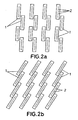
- each row is made of a single piece in the form of bars and are referenced with number 35. They include a longitudinal duct 36 which links the outlets for ink from each one.
- Each of the bars 35 is joined to several cranks 37 perpendicular to separate vertical shafts 38 which have the possibility of rotating, rising and falling.
- the different cranks 37 cause the rotation of the shafts 38 to become converted into a parallel displacement of the bars 35.
- This figure 10 shows the system in a rest/cleaning position in which all the actions aimed at priming the injectors and cleaning the injector pate will be carried out.
- the vertical shafts 38 rotate in the supports 39 and slide downwards starting from the position shown in figure 10 , as shown In position a) of figure 11 .
Landscapes
- Ink Jet (AREA)
Claims (8)
- EIGENSTÄNDIGES TINTENSTRAHLDRUCKMODUL, welches Druckköpfe (5) zum Drucken der erforderlichen Breite in einem einzelnen Durchgang und ein Wartungssystem für die installierten Druckköpfe zusammen mit einem Überdrucksystem und einem System zur thermischen Aufbereitung für die verwendete Tinte umfasst, wobei so viele Module vorhanden sind, wie je nach Anzahl der Tinten und der gewünschten Druckauflösung notwendig sind, und das ferner einen Mechanismus umfasst, der in der Lage ist, eine Düsenplatte abzudecken und die während jedem Entleerungsvorgang austretende Tinte aufzufangen, die Düsenplatte so sauber wie möglich zu halten und darüber hinaus ein Austrocknen der Tinte zu verhindern, wenn das Modul nicht arbeitet, dadurch gekennzeichnet, dass es ein extrudiertes oder maschinell hergestelltes umgekehrtes T-Profil (4) umfasst, auf welchem die Druckköpfe (5) angebracht sind, wobei die Düsenplatte (1) am unteren Teil freiliegt, wobei vorgesehen ist, dass das Metallprofil (4) entlang der gesamten Länge seines Kerns drei horizontale zylindrische Perforationen (6, 8) beinhaltet, von denen die untersten an einem Ende durch einen Kanal (7) miteinander verbunden sind, welcher einen Kreislauf zum Zirkulieren einer Flüssigkeit mit einer gewünschten Temperatur definiert, wohingegen die obere (8) die Funktion eines Verteilers und einer thermischen Aufbereitung der Tinte übernimmt, die durch eines ihrer Enden tritt und über vertikale Kanäle (9), die in dem oberen Teil des Profils (4) eingelassen wurden, und durch jeweilige manuelle Ventile (10) und Schläuche (11) bis zu den Druckköpfen (5) durchläuft.
- EIGENSTÄNDIGES TINTENSTRAHLMODUL nach Anspruch 1, dadurch gekennzeichnet, dass die Tinte den Druckköpfen (5) in jedem Moment mit dem richtigen Druck zugeführt wird, mithilfe eines Arbeitsbehälters (12), der sich eine Ebene unter den Düsenplatten (1) befindet und Elektroventile (15, 17) zum Eintreten von druckbeaufschlagter Luft (15) und druckbeaufschlagter Tinte (17) aufweist, die geschlossen sind, und ein Elektroventil (18), welches mit der Außenseite verbunden und während der Druckphase geöffnet ist; wobei der Arbeitsbehälter (12) gefüllt ist, um den Pegel aufrecht zu halten, während Tinte verbraucht wird, wobei die Elektroventile zum Eintreten von druckbeaufschlagter Tinte (17) und das Elektroventil (18) zur Verbindung mit der Außenseite offen bleiben.
- EIGENSTÄNDIGES TINTENSTRAHLDRUCKMODUL nach Anspruch 1, dadurch gekennzeichnet, dass während der Druckphase die Tinte über den Verteiler (8) den Druckköpfen (5) zugeführt wird, mithilfe eines Arbeitsbehälters (12), der eine Ebene unter den Düsenplatten (1) liegt und ein Elektroventil (17) zum Eintreten von druckbeaufschlagter Tinte in den Behälter (12) aufweist, welches geschlossen ist, und ein Elektroventil (20), welches in Bypass-Verbindung mit einer peristaltischen Pumpe (21) zum Speisen des Verteilers (8) aus dem Behälter (12) verbunden ist und geöffnet ist, wobei die peristaltische Pumpe (21) abgeschaltet und der Arbeitsbehälter (12) gefüllt wird, um den Pegel aufrecht zu halten, da das Elektroventil (17) zum Eintreten der druckbeaufschlagten Tinte geöffnet und der Behälter (12) durch einen Kanal (19) mit der Außenseite verbunden ist.
- EIGENSTÄNDIGES TINTENSTRAHLDRUCKMODUL nach Anspruch 1, dadurch gekennzeichnet, dass während der Druckphase die Tinte über den Verteiler (8) den Druckköpfen (5) zugeführt wird, mithilfe eines Arbeitsbehälters (12), der eine Ebene unter den Düsenplatten (1) liegt und ein Elektroventil (17) zum Eintreten von druckbeaufschlagter Tinte in den Behälter (12) aufweist, welches geschlossen ist, und eine Zentrifugalpumpe (22) zum Speisen des Verteilers (8), die abgeschaltet ist, wobei die Tinte über Kanäle des Laufrades der Pumpe strömt; wobei der Arbeitsbehälter (12) gefüllt wird, um den Pegel aufrecht zu halten, indem das Elektroventil (17) zum Eintreten der Tinte geöffnet wird, und der Behälter (12) über einen Kanal (19) mit der Außenseite verbunden ist.
- EIGENSTÄNDIGES TINTENSTRAHLDRUCKMODUL nach Anspruch 1, dadurch gekennzeichnet, dass der Druckkopf (5) durch Klappen (23) geschützt wird, sodass die Düsen nur noch durch einen kleinen Spalt (24) sichtbar sind und eine kleine Schicht eines absorbierenden Schwammes (25) zwischen der Düsenplatte und den Klappen (23) vorhanden ist, wobei das Druckmodul ferner eine bewegliche konkav geformte Abdeckung (26) mit einem anderen absorbierenden Schwamm (27) umfasst, der überschüssige Tinte aufnimmt, wobei diese überschüssige Tinte durch ein Loch (28) in seiner Basis aufgenommen wird und der absorbierende Schwamm (27) eine Welle (30) bildet, welche die Düsen verschließt und ihre Reinigung unterstützt.
- EIGENSTÄNDIGES TINTENSTRAHLDRUCKMODUL nach Anspruch 1, dadurch gekennzeichnet, dass der Druckkopf (5) die Düsenplatte (1) aufgrund ihrer Positionierung in einem Fenster freiliegen lässt, das in dem Metallträger oder -profil (4) eingelassen wurde, ferner umfassend eine bewegliche konkav geformte Abdeckung (26) mit zwei absorbierenden Schwämmen (31) an den Enden ihres Hohlraums, welche die überschüssige Tinte aufnehmen und am Ende jedes Arbeitsweges einen Spatel (32) reinigen.
- EIGENSTÄNDIGES TINTENSTRAHLDRUCKMODUL nach Anspruch 6, dadurch gekennzeichnet, dass der Spatel (32) frei in einem Zylinder (33) schwingt, welcher senkrecht integral mit einem längslaufenden Rundstab (34) gebildet ist, sodass, wenn sich Letzterer axial bewegt, der Spatel sanfter über die Düsenplatte (1) schwenkt und gleitet.
- EIGENSTÄNDIGES TINTENSTRAHLDRUCKMODUL nach Anspruch 1, dadurch gekennzeichnet, dass die konkav geformten Abdeckungen (26) in zwei parallelen Reihen unterhalb der Flügel des umgekehrten T-Profils (4) angeordnet sind als Einzelstück oder lateraler Stab (35) mit einem längslaufenden Kanal (36) als Sammler für alle Tintenausgänge, wobei beide Stäbe (35) an verschiedenen Kurbeln (37) angebracht sind, die parallel zu einander verlaufen und mit separaten vertikalen Achsen (38) verbunden sind sowie eine Dreh- und Axialbewegung ausführen können zur Parallelverschiebung beider Stäbe (35) aus der Ruheposition in die Arbeitsposition und umgekehrt.
Applications Claiming Priority (2)
| Application Number | Priority Date | Filing Date | Title |
|---|---|---|---|
| ES200603033A ES2302634B1 (es) | 2006-11-28 | 2006-11-28 | Modulo autonomo de impresion por chorro de tinta. |
| PCT/ES2007/000680 WO2008065222A1 (es) | 2006-11-28 | 2007-11-26 | Módulo autónomo de impresión por chorro de tinta |
Publications (3)
| Publication Number | Publication Date |
|---|---|
| EP2090439A1 EP2090439A1 (de) | 2009-08-19 |
| EP2090439A4 EP2090439A4 (de) | 2011-06-29 |
| EP2090439B1 true EP2090439B1 (de) | 2012-09-05 |
Family
ID=39467472
Family Applications (1)
| Application Number | Title | Priority Date | Filing Date |
|---|---|---|---|
| EP07858257A Not-in-force EP2090439B1 (de) | 2006-11-28 | 2007-11-26 | Eigenständiges tintenstrahldruckmodul |
Country Status (3)
| Country | Link |
|---|---|
| EP (1) | EP2090439B1 (de) |
| ES (2) | ES2302634B1 (de) |
| WO (1) | WO2008065222A1 (de) |
Cited By (1)
| Publication number | Priority date | Publication date | Assignee | Title |
|---|---|---|---|---|
| EP3556563B1 (de) * | 2012-09-12 | 2023-04-19 | Linx Printing Technologies Ltd | Tintenstrahldruckkopf und kappe |
Families Citing this family (4)
| Publication number | Priority date | Publication date | Assignee | Title |
|---|---|---|---|---|
| JP5962661B2 (ja) * | 2011-09-21 | 2016-08-03 | コニカミノルタ株式会社 | インクジェット記録装置 |
| ES2472140B2 (es) | 2014-02-07 | 2015-01-29 | Kerajet S.A. | Método de proyección de sólidos sobre una superficie |
| ES2558023B1 (es) * | 2014-07-29 | 2017-03-24 | Kerajet S.A. | Dispositivo, método y máquina de deposición de fluidos sobre una superficie. |
| ES2561727B1 (es) * | 2014-08-29 | 2017-03-24 | Kerajet S.A. | Dispositivo, método y máquina de deposición de fluidos sobre una superficie |
Family Cites Families (9)
| Publication number | Priority date | Publication date | Assignee | Title |
|---|---|---|---|---|
| US4985710A (en) * | 1989-11-29 | 1991-01-15 | Xerox Corporation | Buttable subunits for pagewidth "Roofshooter" printheads |
| US5057854A (en) * | 1990-06-26 | 1991-10-15 | Xerox Corporation | Modular partial bars and full width array printheads fabricated from modular partial bars |
| US5160945A (en) * | 1991-05-10 | 1992-11-03 | Xerox Corporation | Pagewidth thermal ink jet printhead |
| IT1272050B (it) * | 1993-11-10 | 1997-06-11 | Olivetti Canon Ind Spa | Dispositivo stampante parallelo con struttura modulare e relativo procedimento di realizzazione. |
| US6135586A (en) * | 1995-10-31 | 2000-10-24 | Hewlett-Packard Company | Large area inkjet printhead |
| EP0870622A1 (de) * | 1997-04-07 | 1998-10-14 | Xerox Corporation | Tintenstrahldrucker mit einem verbesserten Kühlsystem |
| DE19743804A1 (de) * | 1997-10-02 | 1999-04-08 | Politrust Ag | Druckvorrichtung |
| GB0011916D0 (en) * | 2000-05-17 | 2000-07-05 | Cambridge Consultants | Printing |
| EP1518683B1 (de) * | 2003-09-24 | 2008-03-19 | FUJIFILM Corporation | Tröpfchenausstosskopf und Tintenstrahlaufzeichnungsgerät |
-
2006
- 2006-11-28 ES ES200603033A patent/ES2302634B1/es not_active Expired - Fee Related
-
2007
- 2007-11-26 EP EP07858257A patent/EP2090439B1/de not_active Not-in-force
- 2007-11-26 WO PCT/ES2007/000680 patent/WO2008065222A1/es not_active Ceased
- 2007-11-26 ES ES07858257T patent/ES2392951T3/es active Active
Cited By (1)
| Publication number | Priority date | Publication date | Assignee | Title |
|---|---|---|---|---|
| EP3556563B1 (de) * | 2012-09-12 | 2023-04-19 | Linx Printing Technologies Ltd | Tintenstrahldruckkopf und kappe |
Also Published As
| Publication number | Publication date |
|---|---|
| EP2090439A4 (de) | 2011-06-29 |
| ES2392951T3 (es) | 2012-12-17 |
| WO2008065222A1 (es) | 2008-06-05 |
| ES2302634A1 (es) | 2008-07-16 |
| EP2090439A1 (de) | 2009-08-19 |
| ES2302634B1 (es) | 2009-05-21 |
Similar Documents
| Publication | Publication Date | Title |
|---|---|---|
| EP2090439B1 (de) | Eigenständiges tintenstrahldruckmodul | |
| US5929877A (en) | Method and arrangement for maintaining the nozzles of an ink print head clean by forming a solvent-enriched microclimate in an antechamber containing the nozzles | |
| US7347540B2 (en) | Inkjet printing device | |
| DE69319065T2 (de) | Reinigungsvorrichtung mit Wischblatt für einen Farbstrahldruckkopf | |
| DE60225973T2 (de) | Kontinuierliche Tintenstrahldruckvorrichtung mit integriertem Reiniger | |
| DE60309959T2 (de) | Techniken zur Abgabe von Fluiden mit verbesserter Zuverlässigkeit | |
| US8231208B2 (en) | Liquid ejection head | |
| CN102922881B (zh) | 墨水存放装置和喷墨记录头 | |
| US5424768A (en) | Zero-volume maintenance cap for an ink jet printhead | |
| KR100314876B1 (ko) | 잉크젯프린터 | |
| US20110025770A1 (en) | Wide format printer with multiple ink accumulators | |
| DE2607313B2 (de) | Schutz- und Reinigungsvorrichtung für Schreibköpfe in Tintenschreibeinrichtungen | |
| DE102009020702A1 (de) | Drucksystem zum Bedrucken von Flaschen oder dergleichen Behältern sowie Druckvorrichtung oder -maschine mit einem solchen Drucksystem | |
| CN103660558A (zh) | 液滴喷出装置及其维护方法 | |
| JPH0679879A (ja) | サーマルインクジェットカートリッジ自動クリーニング印刷システム | |
| JPH04273020A (ja) | インクジェットプリンタ用印刷ヘッド機構及び印刷ヘッド機構へのインク充填方法 | |
| US20110216127A1 (en) | Printhead wiping system | |
| KR20080107217A (ko) | 잉크젯 프린터의 노즐칩 세척장치 및 그것을 구비한 잉크젯프린터 | |
| CN103826862B (zh) | 喷墨打印装置 | |
| CN116198227A (zh) | 打印机和喷头清洗方法 | |
| CN110936609A (zh) | 打印头、打印方法、打印系统、储存介质及打印设备 | |
| WO2025237067A1 (zh) | 喷墨头的清理及保养组件 | |
| CN106364165B (zh) | 数码印刷机的喷头刮墨装置及其刮墨方法 | |
| CN107297953A (zh) | 液体喷射头的清洁方法以及液体喷射装置 | |
| JP2022021941A (ja) | クリーニング装置およびそれを備えるインクジェット画像形成装置 |
Legal Events
| Date | Code | Title | Description |
|---|---|---|---|
| PUAI | Public reference made under article 153(3) epc to a published international application that has entered the european phase |
Free format text: ORIGINAL CODE: 0009012 |
|
| 17P | Request for examination filed |
Effective date: 20090625 |
|
| AK | Designated contracting states |
Kind code of ref document: A1 Designated state(s): AT BE BG CH CY CZ DE DK EE ES FI FR GB GR HU IE IS IT LI LT LU LV MC MT NL PL PT RO SE SI SK TR |
|
| DAX | Request for extension of the european patent (deleted) | ||
| A4 | Supplementary search report drawn up and despatched |
Effective date: 20110527 |
|
| REG | Reference to a national code |
Ref country code: DE Ref legal event code: R079 Ref document number: 602007025343 Country of ref document: DE Free format text: PREVIOUS MAIN CLASS: B41J0002155000 Ipc: B41J0002145000 |
|
| GRAP | Despatch of communication of intention to grant a patent |
Free format text: ORIGINAL CODE: EPIDOSNIGR1 |
|
| RIC1 | Information provided on ipc code assigned before grant |
Ipc: B41J 2/145 20060101AFI20120229BHEP Ipc: B41J 2/175 20060101ALI20120229BHEP Ipc: B41J 2/165 20060101ALI20120229BHEP |
|
| GRAS | Grant fee paid |
Free format text: ORIGINAL CODE: EPIDOSNIGR3 |
|
| GRAA | (expected) grant |
Free format text: ORIGINAL CODE: 0009210 |
|
| AK | Designated contracting states |
Kind code of ref document: B1 Designated state(s): AT BE BG CH CY CZ DE DK EE ES FI FR GB GR HU IE IS IT LI LT LU LV MC MT NL PL PT RO SE SI SK TR |
|
| REG | Reference to a national code |
Ref country code: GB Ref legal event code: FG4D |
|
| REG | Reference to a national code |
Ref country code: CH Ref legal event code: EP |
|
| REG | Reference to a national code |
Ref country code: AT Ref legal event code: REF Ref document number: 573908 Country of ref document: AT Kind code of ref document: T Effective date: 20120915 |
|
| REG | Reference to a national code |
Ref country code: IE Ref legal event code: FG4D |
|
| REG | Reference to a national code |
Ref country code: DE Ref legal event code: R096 Ref document number: 602007025343 Country of ref document: DE Effective date: 20121031 |
|
| REG | Reference to a national code |
Ref country code: ES Ref legal event code: FG2A Ref document number: 2392951 Country of ref document: ES Kind code of ref document: T3 Effective date: 20121217 |
|
| REG | Reference to a national code |
Ref country code: AT Ref legal event code: MK05 Ref document number: 573908 Country of ref document: AT Kind code of ref document: T Effective date: 20120905 |
|
| REG | Reference to a national code |
Ref country code: NL Ref legal event code: VDEP Effective date: 20120905 |
|
| PG25 | Lapsed in a contracting state [announced via postgrant information from national office to epo] |
Ref country code: FI Free format text: LAPSE BECAUSE OF FAILURE TO SUBMIT A TRANSLATION OF THE DESCRIPTION OR TO PAY THE FEE WITHIN THE PRESCRIBED TIME-LIMIT Effective date: 20120905 Ref country code: AT Free format text: LAPSE BECAUSE OF FAILURE TO SUBMIT A TRANSLATION OF THE DESCRIPTION OR TO PAY THE FEE WITHIN THE PRESCRIBED TIME-LIMIT Effective date: 20120905 Ref country code: CY Free format text: LAPSE BECAUSE OF FAILURE TO SUBMIT A TRANSLATION OF THE DESCRIPTION OR TO PAY THE FEE WITHIN THE PRESCRIBED TIME-LIMIT Effective date: 20120905 Ref country code: LT Free format text: LAPSE BECAUSE OF FAILURE TO SUBMIT A TRANSLATION OF THE DESCRIPTION OR TO PAY THE FEE WITHIN THE PRESCRIBED TIME-LIMIT Effective date: 20120905 |
|
| REG | Reference to a national code |
Ref country code: LT Ref legal event code: MG4D Effective date: 20120905 |
|
| PG25 | Lapsed in a contracting state [announced via postgrant information from national office to epo] |
Ref country code: SI Free format text: LAPSE BECAUSE OF FAILURE TO SUBMIT A TRANSLATION OF THE DESCRIPTION OR TO PAY THE FEE WITHIN THE PRESCRIBED TIME-LIMIT Effective date: 20120905 Ref country code: SE Free format text: LAPSE BECAUSE OF FAILURE TO SUBMIT A TRANSLATION OF THE DESCRIPTION OR TO PAY THE FEE WITHIN THE PRESCRIBED TIME-LIMIT Effective date: 20120905 Ref country code: LV Free format text: LAPSE BECAUSE OF FAILURE TO SUBMIT A TRANSLATION OF THE DESCRIPTION OR TO PAY THE FEE WITHIN THE PRESCRIBED TIME-LIMIT Effective date: 20120905 Ref country code: GR Free format text: LAPSE BECAUSE OF FAILURE TO SUBMIT A TRANSLATION OF THE DESCRIPTION OR TO PAY THE FEE WITHIN THE PRESCRIBED TIME-LIMIT Effective date: 20121206 |
|
| PGFP | Annual fee paid to national office [announced via postgrant information from national office to epo] |
Ref country code: ES Payment date: 20121029 Year of fee payment: 6 Ref country code: IT Payment date: 20121129 Year of fee payment: 6 |
|
| PG25 | Lapsed in a contracting state [announced via postgrant information from national office to epo] |
Ref country code: EE Free format text: LAPSE BECAUSE OF FAILURE TO SUBMIT A TRANSLATION OF THE DESCRIPTION OR TO PAY THE FEE WITHIN THE PRESCRIBED TIME-LIMIT Effective date: 20120905 Ref country code: CZ Free format text: LAPSE BECAUSE OF FAILURE TO SUBMIT A TRANSLATION OF THE DESCRIPTION OR TO PAY THE FEE WITHIN THE PRESCRIBED TIME-LIMIT Effective date: 20120905 Ref country code: BE Free format text: LAPSE BECAUSE OF FAILURE TO SUBMIT A TRANSLATION OF THE DESCRIPTION OR TO PAY THE FEE WITHIN THE PRESCRIBED TIME-LIMIT Effective date: 20120905 Ref country code: RO Free format text: LAPSE BECAUSE OF FAILURE TO SUBMIT A TRANSLATION OF THE DESCRIPTION OR TO PAY THE FEE WITHIN THE PRESCRIBED TIME-LIMIT Effective date: 20120905 Ref country code: IS Free format text: LAPSE BECAUSE OF FAILURE TO SUBMIT A TRANSLATION OF THE DESCRIPTION OR TO PAY THE FEE WITHIN THE PRESCRIBED TIME-LIMIT Effective date: 20130105 Ref country code: NL Free format text: LAPSE BECAUSE OF FAILURE TO SUBMIT A TRANSLATION OF THE DESCRIPTION OR TO PAY THE FEE WITHIN THE PRESCRIBED TIME-LIMIT Effective date: 20120905 |
|
| PG25 | Lapsed in a contracting state [announced via postgrant information from national office to epo] |
Ref country code: PT Free format text: LAPSE BECAUSE OF FAILURE TO SUBMIT A TRANSLATION OF THE DESCRIPTION OR TO PAY THE FEE WITHIN THE PRESCRIBED TIME-LIMIT Effective date: 20130107 Ref country code: PL Free format text: LAPSE BECAUSE OF FAILURE TO SUBMIT A TRANSLATION OF THE DESCRIPTION OR TO PAY THE FEE WITHIN THE PRESCRIBED TIME-LIMIT Effective date: 20120905 Ref country code: SK Free format text: LAPSE BECAUSE OF FAILURE TO SUBMIT A TRANSLATION OF THE DESCRIPTION OR TO PAY THE FEE WITHIN THE PRESCRIBED TIME-LIMIT Effective date: 20120905 |
|
| REG | Reference to a national code |
Ref country code: CH Ref legal event code: PL |
|
| PLBE | No opposition filed within time limit |
Free format text: ORIGINAL CODE: 0009261 |
|
| STAA | Information on the status of an ep patent application or granted ep patent |
Free format text: STATUS: NO OPPOSITION FILED WITHIN TIME LIMIT |
|
| PG25 | Lapsed in a contracting state [announced via postgrant information from national office to epo] |
Ref country code: BG Free format text: LAPSE BECAUSE OF FAILURE TO SUBMIT A TRANSLATION OF THE DESCRIPTION OR TO PAY THE FEE WITHIN THE PRESCRIBED TIME-LIMIT Effective date: 20121205 Ref country code: CH Free format text: LAPSE BECAUSE OF NON-PAYMENT OF DUE FEES Effective date: 20121130 Ref country code: LI Free format text: LAPSE BECAUSE OF NON-PAYMENT OF DUE FEES Effective date: 20121130 Ref country code: DK Free format text: LAPSE BECAUSE OF FAILURE TO SUBMIT A TRANSLATION OF THE DESCRIPTION OR TO PAY THE FEE WITHIN THE PRESCRIBED TIME-LIMIT Effective date: 20120905 |
|
| 26N | No opposition filed |
Effective date: 20130606 |
|
| REG | Reference to a national code |
Ref country code: FR Ref legal event code: ST Effective date: 20130731 |
|
| GBPC | Gb: european patent ceased through non-payment of renewal fee |
Effective date: 20121205 |
|
| REG | Reference to a national code |
Ref country code: IE Ref legal event code: MM4A |
|
| REG | Reference to a national code |
Ref country code: DE Ref legal event code: R119 Ref document number: 602007025343 Country of ref document: DE Effective date: 20130601 |
|
| PG25 | Lapsed in a contracting state [announced via postgrant information from national office to epo] |
Ref country code: IE Free format text: LAPSE BECAUSE OF NON-PAYMENT OF DUE FEES Effective date: 20121126 Ref country code: DE Free format text: LAPSE BECAUSE OF NON-PAYMENT OF DUE FEES Effective date: 20130601 |
|
| PG25 | Lapsed in a contracting state [announced via postgrant information from national office to epo] |
Ref country code: FR Free format text: LAPSE BECAUSE OF NON-PAYMENT OF DUE FEES Effective date: 20121130 Ref country code: GB Free format text: LAPSE BECAUSE OF NON-PAYMENT OF DUE FEES Effective date: 20121205 Ref country code: MT Free format text: LAPSE BECAUSE OF FAILURE TO SUBMIT A TRANSLATION OF THE DESCRIPTION OR TO PAY THE FEE WITHIN THE PRESCRIBED TIME-LIMIT Effective date: 20120905 |
|
| PG25 | Lapsed in a contracting state [announced via postgrant information from national office to epo] |
Ref country code: TR Free format text: LAPSE BECAUSE OF FAILURE TO SUBMIT A TRANSLATION OF THE DESCRIPTION OR TO PAY THE FEE WITHIN THE PRESCRIBED TIME-LIMIT Effective date: 20120905 Ref country code: MC Free format text: LAPSE BECAUSE OF NON-PAYMENT OF DUE FEES Effective date: 20121130 |
|
| PG25 | Lapsed in a contracting state [announced via postgrant information from national office to epo] |
Ref country code: LU Free format text: LAPSE BECAUSE OF NON-PAYMENT OF DUE FEES Effective date: 20121126 |
|
| PG25 | Lapsed in a contracting state [announced via postgrant information from national office to epo] |
Ref country code: HU Free format text: LAPSE BECAUSE OF FAILURE TO SUBMIT A TRANSLATION OF THE DESCRIPTION OR TO PAY THE FEE WITHIN THE PRESCRIBED TIME-LIMIT Effective date: 20071126 |
|
| PG25 | Lapsed in a contracting state [announced via postgrant information from national office to epo] |
Ref country code: IT Free format text: LAPSE BECAUSE OF NON-PAYMENT OF DUE FEES Effective date: 20131126 |
|
| REG | Reference to a national code |
Ref country code: ES Ref legal event code: FD2A Effective date: 20150703 |
|
| PG25 | Lapsed in a contracting state [announced via postgrant information from national office to epo] |
Ref country code: ES Free format text: LAPSE BECAUSE OF NON-PAYMENT OF DUE FEES Effective date: 20131127 |