EP2090468A1 - Ensemble de boîte à gants pour le tableau de bord d'un véhicule à moteur - Google Patents
Ensemble de boîte à gants pour le tableau de bord d'un véhicule à moteur Download PDFInfo
- Publication number
- EP2090468A1 EP2090468A1 EP20080425084 EP08425084A EP2090468A1 EP 2090468 A1 EP2090468 A1 EP 2090468A1 EP 20080425084 EP20080425084 EP 20080425084 EP 08425084 A EP08425084 A EP 08425084A EP 2090468 A1 EP2090468 A1 EP 2090468A1
- Authority
- EP
- European Patent Office
- Prior art keywords
- door
- assembly according
- control
- glove box
- lock
- Prior art date
- Legal status (The legal status is an assumption and is not a legal conclusion. Google has not performed a legal analysis and makes no representation as to the accuracy of the status listed.)
- Granted
Links
- 230000005540 biological transmission Effects 0.000 claims abstract description 9
- 230000004913 activation Effects 0.000 description 1
- 230000006835 compression Effects 0.000 description 1
- 238000007906 compression Methods 0.000 description 1
- 238000012986 modification Methods 0.000 description 1
- 230000004048 modification Effects 0.000 description 1
Images

Classifications
-
- B—PERFORMING OPERATIONS; TRANSPORTING
- B60—VEHICLES IN GENERAL
- B60R—VEHICLES, VEHICLE FITTINGS, OR VEHICLE PARTS, NOT OTHERWISE PROVIDED FOR
- B60R7/00—Stowing or holding appliances inside vehicle primarily intended for personal property smaller than suit-cases, e.g. travelling articles, or maps
- B60R7/04—Stowing or holding appliances inside vehicle primarily intended for personal property smaller than suit-cases, e.g. travelling articles, or maps in driver or passenger space, e.g. using racks
- B60R7/06—Stowing or holding appliances inside vehicle primarily intended for personal property smaller than suit-cases, e.g. travelling articles, or maps in driver or passenger space, e.g. using racks mounted on or below dashboards
-
- E—FIXED CONSTRUCTIONS
- E05—LOCKS; KEYS; WINDOW OR DOOR FITTINGS; SAFES
- E05B—LOCKS; ACCESSORIES THEREFOR; HANDCUFFS
- E05B13/00—Devices preventing the key or the handle or both from being used
- E05B13/10—Devices preventing the key or the handle or both from being used formed by a lock arranged in the handle
-
- E—FIXED CONSTRUCTIONS
- E05—LOCKS; KEYS; WINDOW OR DOOR FITTINGS; SAFES
- E05B—LOCKS; ACCESSORIES THEREFOR; HANDCUFFS
- E05B63/00—Locks or fastenings with special structural characteristics
- E05B63/14—Arrangement of several locks or locks with several bolts, e.g. arranged one behind the other
- E05B63/143—Arrangement of several locks, e.g. in parallel or series, on one or more wings
-
- E—FIXED CONSTRUCTIONS
- E05—LOCKS; KEYS; WINDOW OR DOOR FITTINGS; SAFES
- E05B—LOCKS; ACCESSORIES THEREFOR; HANDCUFFS
- E05B83/00—Vehicle locks specially adapted for particular types of wing or vehicle
- E05B83/28—Locks for glove compartments, console boxes, fuel inlet covers or the like
- E05B83/30—Locks for glove compartments, console boxes, fuel inlet covers or the like for glove compartments
-
- E—FIXED CONSTRUCTIONS
- E05—LOCKS; KEYS; WINDOW OR DOOR FITTINGS; SAFES
- E05C—BOLTS OR FASTENING DEVICES FOR WINGS, SPECIALLY FOR DOORS OR WINDOWS
- E05C9/00—Arrangements of simultaneously actuated bolts or other securing devices at well-separated positions on the same wing
- E05C9/04—Arrangements of simultaneously actuated bolts or other securing devices at well-separated positions on the same wing with two sliding bars moved in opposite directions when fastening or unfastening
- E05C9/043—Arrangements of simultaneously actuated bolts or other securing devices at well-separated positions on the same wing with two sliding bars moved in opposite directions when fastening or unfastening with crank pins and connecting rods
-
- E—FIXED CONSTRUCTIONS
- E05—LOCKS; KEYS; WINDOW OR DOOR FITTINGS; SAFES
- E05B—LOCKS; ACCESSORIES THEREFOR; HANDCUFFS
- E05B1/00—Knobs or handles for wings; Knobs, handles, or press buttons for locks or latches on wings
- E05B1/0038—Sliding handles, e.g. push buttons
-
- Y—GENERAL TAGGING OF NEW TECHNOLOGICAL DEVELOPMENTS; GENERAL TAGGING OF CROSS-SECTIONAL TECHNOLOGIES SPANNING OVER SEVERAL SECTIONS OF THE IPC; TECHNICAL SUBJECTS COVERED BY FORMER USPC CROSS-REFERENCE ART COLLECTIONS [XRACs] AND DIGESTS
- Y10—TECHNICAL SUBJECTS COVERED BY FORMER USPC
- Y10S—TECHNICAL SUBJECTS COVERED BY FORMER USPC CROSS-REFERENCE ART COLLECTIONS [XRACs] AND DIGESTS
- Y10S292/00—Closure fasteners
- Y10S292/37—Push button operators
-
- Y—GENERAL TAGGING OF NEW TECHNOLOGICAL DEVELOPMENTS; GENERAL TAGGING OF CROSS-SECTIONAL TECHNOLOGIES SPANNING OVER SEVERAL SECTIONS OF THE IPC; TECHNICAL SUBJECTS COVERED BY FORMER USPC CROSS-REFERENCE ART COLLECTIONS [XRACs] AND DIGESTS
- Y10—TECHNICAL SUBJECTS COVERED BY FORMER USPC
- Y10T—TECHNICAL SUBJECTS COVERED BY FORMER US CLASSIFICATION
- Y10T292/00—Closure fasteners
- Y10T292/08—Bolts
- Y10T292/0801—Multiple
- Y10T292/0834—Sliding
Definitions
- the present invention relates to a glove box assembly for a dashboard of a motor vehicle.
- German patent application DE3932909A1 includes the features of the preamble of claim 1 and describes a dashboard of a motor vehicle comprising two glove box compartments, which are arranged one above the other and are provided with respective doors which are upwardly and, respectively, downwardly pivotable to open the glove box compartments.
- the doors are held closed by a closing mechanism borne on a support structure arranged in a fixed position between the two glove box compartments.
- the closing mechanism comprises, for each door, a relative latch, which is movable between an engaged position, in which the door is held in the closed position, and a disengaged position, in which the door is released.
- the latches can be fastened in the engaged position, either together or separately, by operating a key lock, which is also borne on the support structure between the two glove box compartments.
- the known solution described above falls short of being satisfactory, in that the dimensions of the closing mechanism and the position in which the closing mechanism must be arranged on the dashboard between the two glove box compartments constitute constraints which are extremely limiting for the design of the space in the two glove box compartments and the design of the external profile of the dashboard and of the doors in terms of their aesthetical appearance.
- the outer edge of the doors must be appropriately shaped so as to define a recess to allow access to the lock and to the buttons that control the release of the latches.
- the purpose of the present invention is to provide a glove box assembly for a dashboard of a motor vehicle, which overcomes the drawbacks described above in a simple and cost-effective manner.
- a glove box assembly for a dashboard of a motor vehicle comprising:
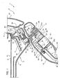
- number 1 indicates, as a whole, a dashboard of a motor vehicle (partially illustrated).
- the dashboard 1 has an external profile that delimits a passenger compartment of the motor vehicle to the front and comprises a glove box assembly 2 (partially illustrated), which, in turn, comprises two glove box compartments 3,4 arranged one beneath the other and defined by respective walls 5,6 fixed to a support structure 7 of the dashboard 1.
- the compartments 3,4 have respective openings 8,9, which can be opened or closed by means of respective doors 11,12.
- the doors 11,12 are downwardly and, respectively, upwardly pivotable from a closed position ( figure 1 ) to an open position (not illustrated).
- the door 11 comprises a wall 15 which delimits the compartment 3 when the door 11 is in the closed position.
- the door 11 also comprises a module 16, which is joined to the wall 15 in a fixed position and externally with respect to the compartment 3 and comprises a wall 17 opposite the wall 15, so as to define a cavity 18.
- the wall 17 defines an opening 19 engaged by two control elements, which constitute part of the module 16 and are defined respectively by a lever 20 and a button 21 comprising respective manually operable plates 20a,21a.
- the lever 20 comprises two appendices 22, which are fixed with respect to the plate 20a, extend in a cantilevered fashion into the cavity 18 and are pivotally connected to the wall 17 about a horizontal axis 23, so that the lever 20 is pivotable between a home position and a raised position (not illustrated).
- the button 21 is arranged above the lever 20 and is releasably connected to a portion 24 that is fixed with respect to the wall 17.
- the button 21 is guided by the portion 24 to slide along an axis 26 from a home position to a retracted position towards the wall 15.
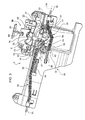
- a coil torsion spring 27 ( figure 3 ) arranged along the axis 23 and a coil compression spring 28 arranged along the axis 26 between the button 21 and a portion 29 of the module 16 are provided to hold the lever 20 and, respectively, the button 21 in the home position.
- the spring 28 is arranged around a rod 30 which is fixed with respect to the plate 21a, extends along the axis 26 across the portion 24, in the cavity 18 and in a cantilevered fashion towards the wall 15, and is aligned with a hole 31 of the portion 29 and of the wall 15.
- the module 16 also comprises a retaining device 32 to hold the door 11 in the closed position.
- the device 32 is housed in the cavity 18 and comprises two rods 33, the outer ends of which are aligned in relation to one another along an axis 34 which is parallel to the axis 23 and define respective latches 35.
- the rods 33 are joined to the wall 17 so as to slide in opposite directions to one another along the axis 34 between an engaged position and a released position.
- the latches 35 protrude laterally with respect to the wall 17 and engage respective side retaining seats (not illustrated), fixed with respect to the wall 5, to hold the door 11 in the closed position; in the released position, the latches 35 are retracted leaving the side retaining seats free so that the compartment 3 can be opened.
- the internal ends of the rods 33 i.e. opposite the latches 35, are defined by respective rectilinear portions 38, which are parallel and spaced with respect to one another and are pushed by respective springs 39 towards the engaged position with respect to the wall 17.
- the device 32 also comprises a rotor 40, which is joined to the wall 17 so as to rotate about an axis 41 perpendicular to the axis 34 and intersecting the axis 34.
- the portions 38 of the rods 33 are diametrically opposite and tangent with respect to the axis 41, and are coupled to respective articulated joints 42 defined by radial teeth of the rotor 40.
- the device 32 is operated directly by the lever 20.
- the motion is transmitted from the lever 20 to the rotor 40 by means of two appendices 43,44 supported in a tangential direction with respect to the axis 41.
- the appendix 44 is defined by a radial tooth of the rotor 40, while the appendix 43 extends in a fixed position from a rear face of the plate 20a, and pivots downwardly about the axis 23 when the plate 20a is raised by the user (in the anti-clockwise direction in figure 1 ). Said rotation causes the tooth 44 to be pushed downwards, thus making the rotor 40 turn (in the clockwise direction in figure 3 ), with the consequent translation of the rods 33 towards the released position.
- the rods 33 automatically return to the engaged position and the lever 20 returns to the home position, due to the action of the springs 39 and 27.
- the module 16 also comprises a lock 50, which is connected to the lever 20, extends in a cantilevered fashion from the plate 20a towards the wall 15 along an axis 51 that is perpendicular to the plate 20a, and which can be operated by means of a key to turn a locking element 52 about the axis 51 with respect to the lever 20.
- the element 52 is arranged in the cavity 18, it is joined to an axial end of the lock 50, and is pivotable between a disengaged position and a locking position.
- the element 52 comprises two appendices 53,54, which engage against a shoulder 55 of the wall 15 and, respectively, against a shoulder 56 of the button 21 when the element 52 is in the locked position, in order to prevent the lever 20 from pivoting to the raised position and, respectively, the button 21 from translating to the retracted position.
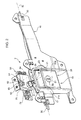
- the assembly 2 comprises a retaining device 58 to hold the door 12 in the closed position.
- the device 58 is housed in a cavity 59, which is arranged vertically between the compartments 3,4 and is defined, towards the passenger compartment, by a portion 60 of the wall 5.
- the device 58 comprises a support element 61 fixed to the portion 60; and a disk 62 comprising a radial tooth that defines a latch 63.
- the disk 62 is pivotally connected to the support element 61 so as to pivot about an axis 64 between an engaged position and a released position.
- the latch 63 engages a keeper 65, which is fixed to the door 12 and defines a ring that protrudes from a lower end of the door 12 and, when the door 12 is in the closed position, engages the cavity 59 passing through a slot 66 obtained in the portion 60; in the released position (not illustrated), the latch 63 disengages the keeper 65.
- the device 58 comprises a stay 69 defined by an arm, which is essentially tangential with respect to the axis 64 and comprises an end 70 which is fixed to the support element 61 and an opposite end 72.
- the arm 69 is elastically flexible along a plane parallel to the axis 64 between a non-deformed condition and a deformed condition.
- the end 72 In the non-deformed condition, the end 72 is adjacent to the support element 61 and defines a shoulder against which a radial tooth 73 of the disk 62 rests tangentially, to hold the disk 62 in the engaged position against the action of an elastic element (not illustrated).
- the end 72 In the deformed condition, the end 72 is at a distance from the support element 61 so that the disk 62 is free to rotate towards the disengaged position under the action of its elastic element.
- the arm 69 is bent into the deformed condition simply by pressing a control portion 74 that protrudes from an intermediate portion of the arm 69.
- the control portion 74 thus defines a button, is fixed with respect to the arm 69, extends essentially along the axis 26 through an opening 75 obtained in the support element 61 and in the portion 60, and faces and is adjacent to the tip of the rod 30 ( figure 1 ).
- the control portion 74 transmits the open command from the button 21 to the latch 63 when the door 11 is in the closed position; when the door 11 is in the open position it remains visible and can be operated directly by a user.
- the door 12 can also be opened when the door 11 is closed and hides the control portion 74, by manually pressing the button 21, which causes the arm 69 to bend via the transmission defined by the control portion 74 and by the rod 30.
- the lock 50 can be used to lock the doors 11 and 12 in the closed position, by turning the key of the lock 50 by 90°.
- the element 52 blocks the lever 20 (since the appendix 53 engages the shoulder 55 and prevents the lever 20 from turning towards the outside) and at the same time blocks the button 21 (since the appendix 54 opposes the retraction of the button 21, thus preventing the activation of the control portion 74).
- the assembly 2 allows the outer edge of the doors 11, 12 and the shape of the compartments 3,4 to be designed in an extremely flexible manner, in that both the controls defined by the lever 20 and by the button 21, and preferably also the lock 50 with the locking element 52, are arranged on the door 11.
- the portion 60 does not need to be directly accessible when the doors 11, 12 are in the closed position.
- the cavity 59 between the compartments 3,4 only houses the device 58, and not the device 32 and/or the lock 50 with the element 52, and is therefore relatively small.
- the transmission defined by the rod 30 and by the control portion 74 is simple and not particularly bulky and allows the compartments 3,4 to be kept close to one another.
- the assembly 2 is relatively simple to assemble, in that the module 16 and the device 58 can be assembled in advance and mounted on the walls 15 and, respectively, 5.
- the command sent via the button 21 to the device 58 could be transmitted using transmission means other than the rod 30 and the control portion 74; and/or the device 32 could also be fixed with respect to the wall 5; and/or the lock 50 could be borne on a portion of the wall 17, instead of on the control element 20; and/or the releasing of the device 32 could be controlled by means of components other than the appendices 43,44 described above.
Landscapes
- Engineering & Computer Science (AREA)
- Mechanical Engineering (AREA)
- Structural Engineering (AREA)
- Lock And Its Accessories (AREA)
- Vehicle Step Arrangements And Article Storage (AREA)
- User Interface Of Digital Computer (AREA)
Priority Applications (5)
| Application Number | Priority Date | Filing Date | Title |
|---|---|---|---|
| DE200860002317 DE602008002317D1 (de) | 2008-02-12 | 2008-02-12 | Handschuhfachanordnung für das Armaturenbrett eines Kraftfahrzeugs |
| EP20080425084 EP2090468B1 (fr) | 2008-02-12 | 2008-02-12 | Ensemble de boîte à gants pour le tableau de bord d'un véhicule à moteur |
| ES08425084T ES2350382T3 (es) | 2008-02-12 | 2008-02-12 | Conjunto de guantera para un salpicadero de un vehículo a motor. |
| BRPI0903077-8A BRPI0903077A2 (pt) | 2008-02-12 | 2009-01-28 | conjunto de porta-luvas para o painel de instrumentos de um veìculo automotor |
| US12/368,850 US8191935B2 (en) | 2008-02-12 | 2009-02-10 | Glove box assembly for a dashboard of a motor vehicle |
Applications Claiming Priority (1)
| Application Number | Priority Date | Filing Date | Title |
|---|---|---|---|
| EP20080425084 EP2090468B1 (fr) | 2008-02-12 | 2008-02-12 | Ensemble de boîte à gants pour le tableau de bord d'un véhicule à moteur |
Publications (2)
| Publication Number | Publication Date |
|---|---|
| EP2090468A1 true EP2090468A1 (fr) | 2009-08-19 |
| EP2090468B1 EP2090468B1 (fr) | 2010-08-25 |
Family
ID=39595579
Family Applications (1)
| Application Number | Title | Priority Date | Filing Date |
|---|---|---|---|
| EP20080425084 Not-in-force EP2090468B1 (fr) | 2008-02-12 | 2008-02-12 | Ensemble de boîte à gants pour le tableau de bord d'un véhicule à moteur |
Country Status (5)
| Country | Link |
|---|---|
| US (1) | US8191935B2 (fr) |
| EP (1) | EP2090468B1 (fr) |
| BR (1) | BRPI0903077A2 (fr) |
| DE (1) | DE602008002317D1 (fr) |
| ES (1) | ES2350382T3 (fr) |
Cited By (6)
| Publication number | Priority date | Publication date | Assignee | Title |
|---|---|---|---|---|
| EP2653638A1 (fr) * | 2012-04-19 | 2013-10-23 | Faurecia Innenraum Systeme GmbH | Mécanisme de verrouillage pour boîte à gants |
| WO2021062149A1 (fr) * | 2019-09-26 | 2021-04-01 | Southco, Inc. | Verrou de boîte à gants de véhicule |
| US11454054B2 (en) * | 2016-09-08 | 2022-09-27 | Nifco Inc. | Lock device |
| WO2022261402A1 (fr) * | 2021-06-11 | 2022-12-15 | Southco, Inc. | Connecteur à cliquet pour verrou de boîte à gants |
| US11814881B2 (en) | 2018-04-03 | 2023-11-14 | Southco, Inc. | Vehicle glove box latch |
| KR102947294B1 (ko) | 2019-09-26 | 2026-04-01 | 사우스코 인코포레이티드 | 차량 글로브 박스 래치 |
Families Citing this family (17)
| Publication number | Priority date | Publication date | Assignee | Title |
|---|---|---|---|---|
| ITMI20080211A1 (it) * | 2008-02-11 | 2009-08-12 | Givi Srl | "valigia per motoveicoli con dispositivo di apertura facilitata" |
| US8191953B2 (en) * | 2010-07-02 | 2012-06-05 | Ford Global Technologies, Llc | Integrated inertial lock and latch for console lid |
| JP5828888B2 (ja) | 2011-03-31 | 2015-12-09 | 株式会社パイオラックス | 開閉部材のロック装置 |
| DE112012003202B4 (de) | 2011-08-02 | 2025-04-30 | Piolax Inc. | Verriegelungsvorrichtung für Öffnungs-/Schließelement |
| CN103850551A (zh) * | 2012-12-03 | 2014-06-11 | 上海同耀汽车配件有限公司 | 手套箱的开启机构 |
| DE102013213217A1 (de) * | 2013-07-05 | 2015-01-08 | Bayerische Motoren Werke Aktiengesellschaft | Schließbaugruppe für einen Gepäckkoffer |
| US20150135782A1 (en) * | 2013-11-04 | 2015-05-21 | Hansen International, Inc. | Push button lock |
| KR102084382B1 (ko) * | 2013-11-05 | 2020-03-04 | 현대모비스 주식회사 | 차량용 글로브 박스의 손잡이 구조 |
| US9045089B1 (en) | 2014-05-15 | 2015-06-02 | Nyx, Inc. | Glove compartment |
| US9810003B2 (en) * | 2015-11-19 | 2017-11-07 | Ford Global Technologies, Llc | Impact resistant door retainer for vehicle glove box |
| KR101856336B1 (ko) * | 2016-07-14 | 2018-05-11 | 현대자동차주식회사 | 차량용 트레이 장치 |
| US10246912B2 (en) * | 2016-11-18 | 2019-04-02 | Ford Global Technologies Llc | Locator feature for automotive interior doors |
| US10794097B2 (en) * | 2017-08-04 | 2020-10-06 | Illinois Tool Works Inc. | Compartment cover release system and method |
| US11492824B2 (en) * | 2018-02-01 | 2022-11-08 | Nifco America Corp. | Latch assembly for glovebox |
| US11077778B2 (en) * | 2019-08-05 | 2021-08-03 | GM Global Technology Operations LLC | Offset dual pawl armrest latch |
| US12221817B2 (en) * | 2020-08-26 | 2025-02-11 | Ford Global Technologies, Llc | Door latch assembly |
| KR102732269B1 (ko) * | 2022-08-26 | 2024-11-21 | 현대모비스 주식회사 | 글로브 박스용 개폐장치 및 이를 포함하는 글로브 박스 어셈블리 |
Citations (3)
| Publication number | Priority date | Publication date | Assignee | Title |
|---|---|---|---|---|
| DE3932909A1 (de) | 1989-10-03 | 1991-04-11 | Bayerische Motoren Werke Ag | Handschuhkasteneinrichtung fuer kraftfahrzeuge |
| EP1193129A1 (fr) * | 2000-09-26 | 2002-04-03 | Visteon Global Technologies, Inc. | Vide-poches notamment pour véhicule automobile. |
| DE102005057189A1 (de) * | 2005-11-29 | 2007-05-31 | Faurecia Innenraum Systeme Gmbh | Staufach für ein Kraftfahrzeug, Handschuhkasten und Instrumententafel |
Family Cites Families (6)
| Publication number | Priority date | Publication date | Assignee | Title |
|---|---|---|---|---|
| JPS5663648U (fr) * | 1979-10-24 | 1981-05-28 | ||
| JPH0463745A (ja) * | 1990-07-04 | 1992-02-28 | Mazda Motor Corp | 車両用グローブボックス装置 |
| JP3033340B2 (ja) * | 1992-04-28 | 2000-04-17 | 日産自動車株式会社 | 自動車のインストルメントパネル内部品組付け構造 |
| US6513354B2 (en) * | 2000-03-14 | 2003-02-04 | Elco Textron Inc. | Dual handle latch |
| JP2006022482A (ja) * | 2004-07-06 | 2006-01-26 | Honda Motor Co Ltd | プッシュボタン式ボックス開放構造 |
| EP1957315B1 (fr) | 2005-11-29 | 2009-02-25 | Faurecia Innenraum Systeme GmbH | Compartiment de rangement pour un vehicule automobile, boite a gants et tableau de bord |
-
2008
- 2008-02-12 DE DE200860002317 patent/DE602008002317D1/de active Active
- 2008-02-12 ES ES08425084T patent/ES2350382T3/es active Active
- 2008-02-12 EP EP20080425084 patent/EP2090468B1/fr not_active Not-in-force
-
2009
- 2009-01-28 BR BRPI0903077-8A patent/BRPI0903077A2/pt not_active Application Discontinuation
- 2009-02-10 US US12/368,850 patent/US8191935B2/en not_active Expired - Fee Related
Patent Citations (3)
| Publication number | Priority date | Publication date | Assignee | Title |
|---|---|---|---|---|
| DE3932909A1 (de) | 1989-10-03 | 1991-04-11 | Bayerische Motoren Werke Ag | Handschuhkasteneinrichtung fuer kraftfahrzeuge |
| EP1193129A1 (fr) * | 2000-09-26 | 2002-04-03 | Visteon Global Technologies, Inc. | Vide-poches notamment pour véhicule automobile. |
| DE102005057189A1 (de) * | 2005-11-29 | 2007-05-31 | Faurecia Innenraum Systeme Gmbh | Staufach für ein Kraftfahrzeug, Handschuhkasten und Instrumententafel |
Cited By (9)
| Publication number | Priority date | Publication date | Assignee | Title |
|---|---|---|---|---|
| EP2653638A1 (fr) * | 2012-04-19 | 2013-10-23 | Faurecia Innenraum Systeme GmbH | Mécanisme de verrouillage pour boîte à gants |
| US11454054B2 (en) * | 2016-09-08 | 2022-09-27 | Nifco Inc. | Lock device |
| US11814881B2 (en) | 2018-04-03 | 2023-11-14 | Southco, Inc. | Vehicle glove box latch |
| WO2021062149A1 (fr) * | 2019-09-26 | 2021-04-01 | Southco, Inc. | Verrou de boîte à gants de véhicule |
| JP2022549497A (ja) * | 2019-09-26 | 2022-11-25 | サウスコ,インコーポレイティド | 車両グローブボックスラッチ |
| JP7587572B2 (ja) | 2019-09-26 | 2024-11-20 | サウスコ,インコーポレイティド | 車両グローブボックスラッチ |
| US12331564B2 (en) | 2019-09-26 | 2025-06-17 | Southco, Inc. | Vehicle glove box latch |
| KR102947294B1 (ko) | 2019-09-26 | 2026-04-01 | 사우스코 인코포레이티드 | 차량 글로브 박스 래치 |
| WO2022261402A1 (fr) * | 2021-06-11 | 2022-12-15 | Southco, Inc. | Connecteur à cliquet pour verrou de boîte à gants |
Also Published As
| Publication number | Publication date |
|---|---|
| US20090206625A1 (en) | 2009-08-20 |
| BRPI0903077A2 (pt) | 2011-08-30 |
| EP2090468B1 (fr) | 2010-08-25 |
| ES2350382T3 (es) | 2011-01-21 |
| DE602008002317D1 (de) | 2010-10-07 |
| US8191935B2 (en) | 2012-06-05 |
Similar Documents
| Publication | Publication Date | Title |
|---|---|---|
| EP2090468B1 (fr) | Ensemble de boîte à gants pour le tableau de bord d'un véhicule à moteur | |
| EP1979566B1 (fr) | Verrous pour portails et portes | |
| CN102597391B (zh) | 用于车辆的门的表面齐平的把手设备 | |
| CN102575486B (zh) | 用于车辆的门的表面齐平的把手设备 | |
| EP2784251B1 (fr) | Serrure de véhicule automobile | |
| JP4755528B2 (ja) | 車両用ドアラッチのリモートコントロール装置 | |
| WO2018128979A1 (fr) | Composant d'intérieur de véhicule | |
| KR20070051925A (ko) | 2개의 회전 폴을 구비한 래치 | |
| US6386600B1 (en) | Vehicle door latch | |
| JP5421083B2 (ja) | ドアロック装置 | |
| US7066506B2 (en) | System for preventing inadvertent locking of a vehicle door | |
| US20060208495A1 (en) | Glove box latch | |
| JP4700561B2 (ja) | 車両用ドアラッチのリモートコントロール装置 | |
| CN105026668A (zh) | 汽车门锁 | |
| EP1518984B1 (fr) | Unité d'actionnement mécanique pour une serrure de porte d'un véhicule automobile et serrure comportant une telle unité | |
| JP3714638B2 (ja) | 非常口用電気ストライク | |
| EP1770232B1 (fr) | Dispositif de contrôle pour portes anti-panique | |
| JP2008133656A (ja) | 電気錠 | |
| KR20210155538A (ko) | 누름 방식으로 개방하는 창호용 잠금장치 | |
| AU2013202551B2 (en) | Latches for gates and doors | |
| JP5965623B2 (ja) | ドアロック装置 | |
| KR200455331Y1 (ko) | 그립형 개폐 장치 | |
| EP4153828B1 (fr) | Verrou rotatif à guide de ressort | |
| CN101970780A (zh) | 锁定解锁装置 | |
| KR100872689B1 (ko) | 자동차용 도어 록킹장치의 스트라이커 조립체 |
Legal Events
| Date | Code | Title | Description |
|---|---|---|---|
| PUAI | Public reference made under article 153(3) epc to a published international application that has entered the european phase |
Free format text: ORIGINAL CODE: 0009012 |
|
| AK | Designated contracting states |
Kind code of ref document: A1 Designated state(s): AT BE BG CH CY CZ DE DK EE ES FI FR GB GR HR HU IE IS IT LI LT LU LV MC MT NL NO PL PT RO SE SI SK TR |
|
| AX | Request for extension of the european patent |
Extension state: AL BA MK RS |
|
| 17P | Request for examination filed |
Effective date: 20091216 |
|
| GRAP | Despatch of communication of intention to grant a patent |
Free format text: ORIGINAL CODE: EPIDOSNIGR1 |
|
| AKX | Designation fees paid |
Designated state(s): DE ES FR GB IT TR |
|
| GRAS | Grant fee paid |
Free format text: ORIGINAL CODE: EPIDOSNIGR3 |
|
| GRAA | (expected) grant |
Free format text: ORIGINAL CODE: 0009210 |
|
| AK | Designated contracting states |
Kind code of ref document: B1 Designated state(s): DE ES FR GB IT TR |
|
| REG | Reference to a national code |
Ref country code: GB Ref legal event code: FG4D |
|
| REF | Corresponds to: |
Ref document number: 602008002317 Country of ref document: DE Date of ref document: 20101007 Kind code of ref document: P |
|
| REG | Reference to a national code |
Ref country code: ES Ref legal event code: FG2A Effective date: 20110111 |
|
| PLBE | No opposition filed within time limit |
Free format text: ORIGINAL CODE: 0009261 |
|
| STAA | Information on the status of an ep patent application or granted ep patent |
Free format text: STATUS: NO OPPOSITION FILED WITHIN TIME LIMIT |
|
| 26N | No opposition filed |
Effective date: 20110526 |
|
| REG | Reference to a national code |
Ref country code: DE Ref legal event code: R097 Ref document number: 602008002317 Country of ref document: DE Effective date: 20110526 |
|
| PGFP | Annual fee paid to national office [announced via postgrant information from national office to epo] |
Ref country code: TR Payment date: 20120125 Year of fee payment: 5 |
|
| PGFP | Annual fee paid to national office [announced via postgrant information from national office to epo] |
Ref country code: ES Payment date: 20130214 Year of fee payment: 6 Ref country code: GB Payment date: 20130207 Year of fee payment: 6 |
|
| PG25 | Lapsed in a contracting state [announced via postgrant information from national office to epo] |
Ref country code: TR Free format text: LAPSE BECAUSE OF FAILURE TO SUBMIT A TRANSLATION OF THE DESCRIPTION OR TO PAY THE FEE WITHIN THE PRESCRIBED TIME-LIMIT Effective date: 20100825 |
|
| GBPC | Gb: european patent ceased through non-payment of renewal fee |
Effective date: 20140212 |
|
| PG25 | Lapsed in a contracting state [announced via postgrant information from national office to epo] |
Ref country code: GB Free format text: LAPSE BECAUSE OF NON-PAYMENT OF DUE FEES Effective date: 20140212 |
|
| REG | Reference to a national code |
Ref country code: ES Ref legal event code: FD2A Effective date: 20150327 |
|
| PG25 | Lapsed in a contracting state [announced via postgrant information from national office to epo] |
Ref country code: ES Free format text: LAPSE BECAUSE OF NON-PAYMENT OF DUE FEES Effective date: 20140213 |
|
| REG | Reference to a national code |
Ref country code: FR Ref legal event code: PLFP Year of fee payment: 9 |
|
| REG | Reference to a national code |
Ref country code: FR Ref legal event code: PLFP Year of fee payment: 10 |
|
| PGFP | Annual fee paid to national office [announced via postgrant information from national office to epo] |
Ref country code: FR Payment date: 20170224 Year of fee payment: 10 |
|
| PGFP | Annual fee paid to national office [announced via postgrant information from national office to epo] |
Ref country code: IT Payment date: 20170206 Year of fee payment: 10 |
|
| PGFP | Annual fee paid to national office [announced via postgrant information from national office to epo] |
Ref country code: DE Payment date: 20170428 Year of fee payment: 10 |
|
| REG | Reference to a national code |
Ref country code: DE Ref legal event code: R119 Ref document number: 602008002317 Country of ref document: DE |
|
| REG | Reference to a national code |
Ref country code: FR Ref legal event code: ST Effective date: 20181031 |
|
| PG25 | Lapsed in a contracting state [announced via postgrant information from national office to epo] |
Ref country code: DE Free format text: LAPSE BECAUSE OF NON-PAYMENT OF DUE FEES Effective date: 20180901 |
|
| PG25 | Lapsed in a contracting state [announced via postgrant information from national office to epo] |
Ref country code: FR Free format text: LAPSE BECAUSE OF NON-PAYMENT OF DUE FEES Effective date: 20180228 Ref country code: IT Free format text: LAPSE BECAUSE OF NON-PAYMENT OF DUE FEES Effective date: 20180212 |