EP2090690A1 - Türverschlussvorrichtung mit Wärmeschutz und Wärmeschutzverfahren für eine Türverschlussvorrichtung in einer Haushaltsvorrichtung - Google Patents
Türverschlussvorrichtung mit Wärmeschutz und Wärmeschutzverfahren für eine Türverschlussvorrichtung in einer HaushaltsvorrichtungInfo
- Publication number
- EP2090690A1 EP2090690A1 EP08151585A EP08151585A EP2090690A1 EP 2090690 A1 EP2090690 A1 EP 2090690A1 EP 08151585 A EP08151585 A EP 08151585A EP 08151585 A EP08151585 A EP 08151585A EP 2090690 A1 EP2090690 A1 EP 2090690A1
- Authority
- EP
- European Patent Office
- Prior art keywords
- estimated temperature
- door lock
- lock device
- incremented
- locking mechanism
- Prior art date
- Legal status (The legal status is an assumption and is not a legal conclusion. Google has not performed a legal analysis and makes no representation as to the accuracy of the status listed.)
- Granted
Links
- 238000000034 method Methods 0.000 title claims description 23
- 238000012360 testing method Methods 0.000 claims description 15
- 238000005406 washing Methods 0.000 description 10
- 238000001816 cooling Methods 0.000 description 4
- 238000013021 overheating Methods 0.000 description 4
- 230000003111 delayed effect Effects 0.000 description 3
- 238000010586 diagram Methods 0.000 description 1
- 230000000694 effects Effects 0.000 description 1
- 238000004519 manufacturing process Methods 0.000 description 1
- 238000012986 modification Methods 0.000 description 1
- 230000004048 modification Effects 0.000 description 1
- GOLXNESZZPUPJE-UHFFFAOYSA-N spiromesifen Chemical compound CC1=CC(C)=CC(C)=C1C(C(O1)=O)=C(OC(=O)CC(C)(C)C)C11CCCC1 GOLXNESZZPUPJE-UHFFFAOYSA-N 0.000 description 1
- XLYOFNOQVPJJNP-UHFFFAOYSA-N water Substances O XLYOFNOQVPJJNP-UHFFFAOYSA-N 0.000 description 1
Images

Classifications
-
- D—TEXTILES; PAPER
- D06—TREATMENT OF TEXTILES OR THE LIKE; LAUNDERING; FLEXIBLE MATERIALS NOT OTHERWISE PROVIDED FOR
- D06F—LAUNDERING, DRYING, IRONING, PRESSING OR FOLDING TEXTILE ARTICLES
- D06F39/00—Details of washing machines not specific to a single type of machines covered by groups D06F9/00 - D06F27/00
- D06F39/12—Casings; Tubs
- D06F39/14—Doors or covers; Securing means therefor
-
- D—TEXTILES; PAPER
- D06—TREATMENT OF TEXTILES OR THE LIKE; LAUNDERING; FLEXIBLE MATERIALS NOT OTHERWISE PROVIDED FOR
- D06F—LAUNDERING, DRYING, IRONING, PRESSING OR FOLDING TEXTILE ARTICLES
- D06F37/00—Details specific to washing machines covered by groups D06F21/00 - D06F25/00
- D06F37/42—Safety arrangements, e.g. for stopping rotation of the receptacle upon opening of the casing door
Definitions
- the present invention relates to a door lock device with thermal protection and to a method for thermal protection of a door lock device in a household appliance.
- Delayed door lock devices enable opening the door of the appliance only after a time interval has elapsed since a washing cycle has been completed or paused in a condition wherein opening the door is allowed (e.g. there is no water in the washing compartment). Delayed door lock devices are based on use of thermosensitive components (normally PTC thermistors coupled to bimetallic deformable components). In use, PTC thermistors are energized by supplying a current and rapidly increase their temperature, causing deformation of bimetal components. A locking mechanism is thus actuated to a closing position, as long as the PTC thermistors are energized. When power supply is removed, PTC thermistors cool down and the bimetal components switch to a rest configuration in which the locking mechanism is released.
- thermosensitive components normally PTC thermistors coupled to bimetallic deformable components.
- PTC thermistors are energized by supplying a current and rapidly increase their temperature, causing deformation of bimetal components. A locking mechanism is thus
- a drawback of delayed door lock devices resides in that a current must be supplied to the PTC thermistors during a whole washing cycle. Therefore, power consumption is quite high. Moreover, users must every time wait for a while before being allowed to open the door, until the PTC thermistors cool and the locking mechanism is released.
- Instant door lock devices are operated by current pulses that are supplied by a power source in response to commands of a user. Subsequent pulses alternately lock and release door lock devices. A control button is normally available to this end.
- Instant door lock devices do not require continuous power supply during washing cycles and, as a rule, may be immediately operated at any time, provided that cycle progress so allows.
- temperature of door lock devices may dramatically increase following upon repeated current pulses and some thermal protection is required to prevent overheating.
- additional circuits must be provided to forbid release of current pulses when temperature of locking devices exceeds a safety range.
- thermal protection circuits include thermosensitive components and may be based on PTC thermistors. Again, additional costs are incurred and overall risk of component failure is increased.
- the object of the present invention is to provide a door lock device with thermal protection and a method for thermal protection of a door lock device that are free from the above described drawbacks.
- a door lock device and a method for thermal protection of a door lock device are provided, as claimed in claims 1 and 10, respectively.
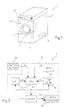
- a household appliance that in the embodiment herein described is a washer, is generally designated by the reference numeral 1.
- the appliance 1 comprises a body 2, a washing compartment 3, a power supply unit 4, both accommodated in the body 2, and a door 5, for providing access to the washing compartment 3.
- the washing compartment 3 is a rotary basket and the door is arranged on a front panel 2a of the body 2.
- the door 5 is equipped with an instant-type door lock device 7 to prevent operation of the appliance 1 when the door 5 is not properly locked.
- the door lock device 7 comprises a locking mechanism 10, a driving device 11 and a logic control unit 12.
- the locking mechanism 10 is electrically actuatable by current pulses I to alternately lock and unlock the door 5.
- the locking mechanism 10 maintains its current configuration, either locked or unlocked, until another current pulse I is received.
- the driving device 11 is supplied by the power supply unit 4 and is moreover coupled to the locking mechanism 10 to deliver current pulses I, thereby causing the locking mechanism 10 to alternately lock and unlock. Current pulses I are released by the driving device 11 in response to driving signals S D provided by the logic control unit 12, as explained hereinafter.
- the logic control unit 12 comprises a main module 15, a temperature estimation module 16, a test module 17 and a state storage element 18.
- the logic control unit 12 is coupled to a control button 20, provided on the front panel 2a of the body 2 and operable by a user to produce lock/unlock signals S LU for the logic control unit 12 (see also figure 1 ).
- the main module 15 controls operation of the whole appliance 1 and, in particular, determines progress of a washing cycle according to a program selected by a user. Among other functions, the main module 15 generates a consent signal S C to enable opening the door 5 when progress of the washing cycle so allows.
- the temperature estimation module 16 determines and cyclically updates estimated values of an operative temperature T of actuating coils 10a of the locking mechanism 10, which run a risk of overheating if several current pulses are supplied in a short time.
- estimated values T C of the operative temperature T are supplied to the test module 17.
- the state storage element 18 stores a state logic signal ST that is indicative of a current state of the locking mechanism 10. Namely, the state logic signal ST has a first logic value when the locking mechanism 10 is locked and a second logic value when the locking mechanism 10 is unlocked. The state logic value is updated every time the locking mechanism 10 is operated.
- the test module 17 determines whether or not a current pulse I is to be delivered to the actuating coils 10a of the locking mechanism 10 in response to lock/unlock signals S LU that are generated when the control button 20 is operated by a user.
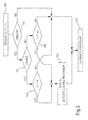
- determination is made by the test module 17 in accordance to a procedure illustrated in figure 3 .
- the procedure is activated upon operation of the control button 20 by the user.
- test module 17 receives the consent signal S C from the main module 15, the state logic signal ST from the state storage element 18 and the currently estimated value T C of the operative temperature T from the temperature estimation module 16.
- the consent signal S C is first tested to check consent of the main module 15 to pulse generation (block 110). If consent is denied (block 110, output NO), the procedure is terminated (block 120). Otherwise (block 110, output YES), the state logic signal ST is tested to identify the current state of the locking mechanism 10 (block 130).
- an incremented temperature value T I is compared to a first safety temperature threshold T TH1 (test condition: T I ⁇ T TH1 ; block 140).
- the incremented temperature value T I is an estimation of the operative temperature T that is expected as a consequence of delivering another current pulse I.
- the incremented temperature value T I is calculated by adding an expected temperature increment ⁇ T, associated with delivery of a current pulse I, to the currently estimated value T C of the operative temperature T.
- the expected temperature increment ⁇ T is a constant, independent of the currently estimated value T C of the operative temperature T.
- the incremented temperature value T I is calculated in advance to possibly delivering a current pulse I.
- a driving signal S D is sent to the driving device 11 to trigger a current pulse I and actuate the locking mechanism 10 (block 150).
- the driving signal S D is also provided to the temperature estimation module 16, for the purpose of updating the currently estimated value T C , and to the state storage element 18, that switches the state logic signal ST between its first and second logic values. Otherwise (block 140, output YES), the procedure is terminated (block 120), thereby preventing delivery of current pulses I by the driving device 11, because the incremented temperature value T I exceeds a safety range and the actuation coils 10a of the locking mechanism 10 may be subjected to overheating.
- the incremented temperature value T I is calculated and compared to a second safety temperature threshold T TH2 (test condition: T I ⁇ T TH2 ; block 160).
- the second safety temperature threshold T TH2 is lower than the first safety temperature threshold T TH1 .
- the second safety temperature threshold T TH2 is equal to T TH1 - ⁇ T, so that in practice in block 160 the following condition is tested: T C + 2 ⁇ ⁇ ⁇ T ⁇ T TH ⁇ 1
- the locking mechanism 10 is actuated by sending a driving signal S D to the driving device 11, to trigger a current pulse I (block 150). Otherwise (block 140, output YES), the procedure is terminated (block 120).
- the driving device 11 delivers current pulses I in response to commands imparted by a user through the control button 20, unless generation of current pulses I is inhibited by the logic control unit 12, in order to prevent overheating of the actuating coils 10a of the locking mechanism 10.
- Different safety temperature thresholds are used to enable switching of the locking mechanism 10 from the locked state to the unlocked state and from the unlocked state to the locked state.
- a current pulse to lock the door 5 through the locking mechanism 10 is permitted only in case another current pulse I can be soon after delivered to unlock the door 5 without exceeding the highest temperature safety threshold (i.e. the first temperature safety threshold T TH1 ).
- the door lock device 7 is always in condition to respond without any delay to a request to unlock the door 5.
- the incremented temperature value T I is compared to a single safety temperature threshold, irrespective of the locked or unlocked state of the locking mechanism 10. In this case, the state storage element 18 is not required.
- the estimation of the operative temperature T is determined and updated by the temperature estimation module 16 according to the procedure illustrated in figure 4 .
- a minimum temperature value T MIN is selected as the currently estimated value T C of the operative temperature T during an initialization step (block 200).
- the minimum temperature value T MIN is the highest temperature value that may be reached in the working environment of the locking mechanism 10 during a washing cycle.
- the minimum temperature value T MIN is the highest temperature that the actuating coils 10a of the locking mechanism 10 may reach in case no current pulses I are sent by the driving device 11. Risk of underestimating the operative temperature T is thus avoided.
- the minimum temperature value T MIN is 60°C.
- T 0 is the most recent peak value of the currently estimated value of the operative temperature
- t is time elapsed from the most recent peak value
- ⁇ is a calibratable time constant.
- the door lock device 7 provides for extremely simple, yet effective thermal protection of actuating coils 10a of the locking mechanism 10, without any need of additional components.
- the existing logic control unit may be configured to carry out required test and temperature updating procedures as described above.
- estimated values of the operative temperature may be updated according to different procedures. For example, effect of current pulses may be accounted for by variable temperature increments as a function of currently estimated temperature. Also cooling may be determined according to different cooling laws.
Landscapes
- Engineering & Computer Science (AREA)
- Textile Engineering (AREA)
- Main Body Construction Of Washing Machines And Laundry Dryers (AREA)
- Lock And Its Accessories (AREA)
- Special Wing (AREA)
- Electric Ovens (AREA)
Priority Applications (5)
| Application Number | Priority Date | Filing Date | Title |
|---|---|---|---|
| AT08151585T ATE507342T1 (de) | 2008-02-18 | 2008-02-18 | Türverschlussvorrichtung mit wärmeschutz und wärmeschutzverfahren für eine türverschlussvorrichtung in einer haushaltsvorrichtung |
| EP08151585A EP2090690B1 (de) | 2008-02-18 | 2008-02-18 | Türverschlussvorrichtung mit Wärmeschutz und Wärmeschutzverfahren für eine Türverschlussvorrichtung in einer Haushaltsvorrichtung |
| DE602008006516T DE602008006516D1 (de) | 2008-02-18 | 2008-02-18 | Türverschlussvorrichtung mit Wärmeschutz und Wärmeschutzverfahren für eine Türverschlussvorrichtung in einer Haushaltsvorrichtung |
| PL08151585T PL2090690T3 (pl) | 2008-02-18 | 2008-02-18 | Urządzenie do blokowania drzwi z zabezpieczeniem termicznym oraz sposób termicznego zabezpieczenia urządzenia blokującego drzwi w urządzeniu gospodarstwa domowego |
| PCT/EP2008/010997 WO2009103331A1 (en) | 2008-02-18 | 2008-12-22 | Door lock device with thermal protection and method for thermal protection of a door lock device in a household appliance |
Applications Claiming Priority (1)
| Application Number | Priority Date | Filing Date | Title |
|---|---|---|---|
| EP08151585A EP2090690B1 (de) | 2008-02-18 | 2008-02-18 | Türverschlussvorrichtung mit Wärmeschutz und Wärmeschutzverfahren für eine Türverschlussvorrichtung in einer Haushaltsvorrichtung |
Publications (2)
| Publication Number | Publication Date |
|---|---|
| EP2090690A1 true EP2090690A1 (de) | 2009-08-19 |
| EP2090690B1 EP2090690B1 (de) | 2011-04-27 |
Family
ID=39688948
Family Applications (1)
| Application Number | Title | Priority Date | Filing Date |
|---|---|---|---|
| EP08151585A Not-in-force EP2090690B1 (de) | 2008-02-18 | 2008-02-18 | Türverschlussvorrichtung mit Wärmeschutz und Wärmeschutzverfahren für eine Türverschlussvorrichtung in einer Haushaltsvorrichtung |
Country Status (5)
| Country | Link |
|---|---|
| EP (1) | EP2090690B1 (de) |
| AT (1) | ATE507342T1 (de) |
| DE (1) | DE602008006516D1 (de) |
| PL (1) | PL2090690T3 (de) |
| WO (1) | WO2009103331A1 (de) |
Citations (4)
| Publication number | Priority date | Publication date | Assignee | Title |
|---|---|---|---|---|
| DE2708086A1 (de) * | 1976-03-18 | 1977-09-22 | Texas Instruments Italia Spa | Tuerblockierungsvorrichtung |
| EP0965677A1 (de) * | 1998-06-11 | 1999-12-22 | BITRON S.p.A. | Türschliessvorrichtung für ein elektrisches Haushaltsgerät |
| GB2344849A (en) * | 1998-12-18 | 2000-06-21 | Bitron Spa | Electrically controlled door lock detent |
| DE19953633A1 (de) * | 1999-11-09 | 2001-05-10 | Diehl Ako Stiftung Gmbh & Co | Steuereinrichtung einer Waschmaschine oder eines Wäschetrockners |
-
2008
- 2008-02-18 DE DE602008006516T patent/DE602008006516D1/de active Active
- 2008-02-18 EP EP08151585A patent/EP2090690B1/de not_active Not-in-force
- 2008-02-18 PL PL08151585T patent/PL2090690T3/pl unknown
- 2008-02-18 AT AT08151585T patent/ATE507342T1/de not_active IP Right Cessation
- 2008-12-22 WO PCT/EP2008/010997 patent/WO2009103331A1/en not_active Ceased
Patent Citations (4)
| Publication number | Priority date | Publication date | Assignee | Title |
|---|---|---|---|---|
| DE2708086A1 (de) * | 1976-03-18 | 1977-09-22 | Texas Instruments Italia Spa | Tuerblockierungsvorrichtung |
| EP0965677A1 (de) * | 1998-06-11 | 1999-12-22 | BITRON S.p.A. | Türschliessvorrichtung für ein elektrisches Haushaltsgerät |
| GB2344849A (en) * | 1998-12-18 | 2000-06-21 | Bitron Spa | Electrically controlled door lock detent |
| DE19953633A1 (de) * | 1999-11-09 | 2001-05-10 | Diehl Ako Stiftung Gmbh & Co | Steuereinrichtung einer Waschmaschine oder eines Wäschetrockners |
Also Published As
| Publication number | Publication date |
|---|---|
| PL2090690T3 (pl) | 2011-09-30 |
| WO2009103331A1 (en) | 2009-08-27 |
| ATE507342T1 (de) | 2011-05-15 |
| EP2090690B1 (de) | 2011-04-27 |
| DE602008006516D1 (de) | 2011-06-09 |
Similar Documents
| Publication | Publication Date | Title |
|---|---|---|
| US7535191B2 (en) | Power window device | |
| US8836173B2 (en) | Domestic appliance having automatic switch-off | |
| KR101407961B1 (ko) | 세탁기의 도어 록 제어 장치 및 그 방법 | |
| JP2006026405A (ja) | 家庭電化製品、即ち、電気駆動可能なドアのブロック/リリース装置を有する洗濯乾燥機 | |
| US20080202170A1 (en) | Appliance with a Controllable Protection Device | |
| CN108798358B (zh) | 用于车辆关闭元件的控制系统和控制方法 | |
| CN100472064C (zh) | 用于控制一个或多个形状记忆致动器的方法和系统 | |
| JP5356913B2 (ja) | 電子キー | |
| WO1996034510A2 (en) | Safety device for an electric heating appliance | |
| CN102227529B (zh) | 用于家用电器的电磁门锁的安全控制系统 | |
| US6897782B2 (en) | Thermal monitoring of an electric load element | |
| CN106088835A (zh) | 一种电磁锁的控制装置、电磁锁及其控制方法 | |
| EP2090690B1 (de) | Türverschlussvorrichtung mit Wärmeschutz und Wärmeschutzverfahren für eine Türverschlussvorrichtung in einer Haushaltsvorrichtung | |
| US7973431B2 (en) | Circuit arrangement for locking and/or unlocking a door lock, especially in an electric appliance | |
| CN105054810A (zh) | 家用电器及其控制方法 | |
| CN109945246B (zh) | 电烹饪设备、电烹饪设备的防误触发方法和装置 | |
| US5175413A (en) | Fail-safe relay drive system for cooking apparatus | |
| RU2452457C2 (ru) | Способ обеспечения безопасности электронагревательных приборов и предохранительное приспособление для осуществления упомянутого способа | |
| ES2276957T3 (es) | Un metodo para el control automatico de un electrodomestido conductor de agua y electrodomestico correspondiente. | |
| EP2123820B1 (de) | Elektronische Steuervorrichtung für ein elektrisches Haushaltsgerät mit Zugangstür | |
| US7253635B2 (en) | Method for checking the electrical safety of a household appliance and corresponding household appliance | |
| RU2658377C1 (ru) | Бытовой прибор, снабженный устройством блокировки средств ввода | |
| US20040060546A1 (en) | Internal combustion engine controller and method for the operating of an internal combustion engine controller | |
| CA2346365A1 (en) | Method for estimating the duration of the interruptions in the supply from the electric mains in an electric apparatus having an electronic control, in particular a household appliance, and apparatus implementing such a method | |
| EP3642407B1 (de) | Verfahren und vorrichtung zum dosieren von wasser in einer dampfkammer |
Legal Events
| Date | Code | Title | Description |
|---|---|---|---|
| PUAI | Public reference made under article 153(3) epc to a published international application that has entered the european phase |
Free format text: ORIGINAL CODE: 0009012 |
|
| AK | Designated contracting states |
Kind code of ref document: A1 Designated state(s): AT BE BG CH CY CZ DE DK EE ES FI FR GB GR HR HU IE IS IT LI LT LU LV MC MT NL NO PL PT RO SE SI SK TR |
|
| AX | Request for extension of the european patent |
Extension state: AL BA MK RS |
|
| 17P | Request for examination filed |
Effective date: 20100120 |
|
| AKX | Designation fees paid |
Designated state(s): AT BE BG CH CY CZ DE DK EE ES FI FR GB GR HR HU IE IS IT LI LT LU LV MC MT NL NO PL PT RO SE SI SK TR |
|
| GRAP | Despatch of communication of intention to grant a patent |
Free format text: ORIGINAL CODE: EPIDOSNIGR1 |
|
| GRAS | Grant fee paid |
Free format text: ORIGINAL CODE: EPIDOSNIGR3 |
|
| RAP1 | Party data changed (applicant data changed or rights of an application transferred) |
Owner name: ELECTROLUX HOME PRODUCTS CORPORATION N.V. |
|
| GRAA | (expected) grant |
Free format text: ORIGINAL CODE: 0009210 |
|
| AK | Designated contracting states |
Kind code of ref document: B1 Designated state(s): AT BE BG CH CY CZ DE DK EE ES FI FR GB GR HR HU IE IS IT LI LT LU LV MC MT NL NO PL PT RO SE SI SK TR |
|
| REG | Reference to a national code |
Ref country code: GB Ref legal event code: FG4D |
|
| REG | Reference to a national code |
Ref country code: CH Ref legal event code: EP |
|
| REG | Reference to a national code |
Ref country code: IE Ref legal event code: FG4D |
|
| REF | Corresponds to: |
Ref document number: 602008006516 Country of ref document: DE Date of ref document: 20110609 Kind code of ref document: P |
|
| REG | Reference to a national code |
Ref country code: DE Ref legal event code: R096 Ref document number: 602008006516 Country of ref document: DE Effective date: 20110609 |
|
| RAP2 | Party data changed (patent owner data changed or rights of a patent transferred) |
Owner name: ELECTROLUX HOME PRODUCTS CORPORATION N.V. |
|
| REG | Reference to a national code |
Ref country code: NL Ref legal event code: VDEP Effective date: 20110427 |
|
| LTIE | Lt: invalidation of european patent or patent extension |
Effective date: 20110427 |
|
| REG | Reference to a national code |
Ref country code: PL Ref legal event code: T3 |
|
| PG25 | Lapsed in a contracting state [announced via postgrant information from national office to epo] |
Ref country code: PT Free format text: LAPSE BECAUSE OF FAILURE TO SUBMIT A TRANSLATION OF THE DESCRIPTION OR TO PAY THE FEE WITHIN THE PRESCRIBED TIME-LIMIT Effective date: 20110829 Ref country code: SE Free format text: LAPSE BECAUSE OF FAILURE TO SUBMIT A TRANSLATION OF THE DESCRIPTION OR TO PAY THE FEE WITHIN THE PRESCRIBED TIME-LIMIT Effective date: 20110427 Ref country code: HR Free format text: LAPSE BECAUSE OF FAILURE TO SUBMIT A TRANSLATION OF THE DESCRIPTION OR TO PAY THE FEE WITHIN THE PRESCRIBED TIME-LIMIT Effective date: 20110427 Ref country code: NO Free format text: LAPSE BECAUSE OF FAILURE TO SUBMIT A TRANSLATION OF THE DESCRIPTION OR TO PAY THE FEE WITHIN THE PRESCRIBED TIME-LIMIT Effective date: 20110727 Ref country code: LT Free format text: LAPSE BECAUSE OF FAILURE TO SUBMIT A TRANSLATION OF THE DESCRIPTION OR TO PAY THE FEE WITHIN THE PRESCRIBED TIME-LIMIT Effective date: 20110427 |
|
| PG25 | Lapsed in a contracting state [announced via postgrant information from national office to epo] |
Ref country code: SI Free format text: LAPSE BECAUSE OF FAILURE TO SUBMIT A TRANSLATION OF THE DESCRIPTION OR TO PAY THE FEE WITHIN THE PRESCRIBED TIME-LIMIT Effective date: 20110427 Ref country code: ES Free format text: LAPSE BECAUSE OF FAILURE TO SUBMIT A TRANSLATION OF THE DESCRIPTION OR TO PAY THE FEE WITHIN THE PRESCRIBED TIME-LIMIT Effective date: 20110807 Ref country code: GR Free format text: LAPSE BECAUSE OF FAILURE TO SUBMIT A TRANSLATION OF THE DESCRIPTION OR TO PAY THE FEE WITHIN THE PRESCRIBED TIME-LIMIT Effective date: 20110728 Ref country code: AT Free format text: LAPSE BECAUSE OF FAILURE TO SUBMIT A TRANSLATION OF THE DESCRIPTION OR TO PAY THE FEE WITHIN THE PRESCRIBED TIME-LIMIT Effective date: 20110427 Ref country code: IS Free format text: LAPSE BECAUSE OF FAILURE TO SUBMIT A TRANSLATION OF THE DESCRIPTION OR TO PAY THE FEE WITHIN THE PRESCRIBED TIME-LIMIT Effective date: 20110827 Ref country code: BE Free format text: LAPSE BECAUSE OF FAILURE TO SUBMIT A TRANSLATION OF THE DESCRIPTION OR TO PAY THE FEE WITHIN THE PRESCRIBED TIME-LIMIT Effective date: 20110427 Ref country code: CY Free format text: LAPSE BECAUSE OF FAILURE TO SUBMIT A TRANSLATION OF THE DESCRIPTION OR TO PAY THE FEE WITHIN THE PRESCRIBED TIME-LIMIT Effective date: 20110427 Ref country code: FI Free format text: LAPSE BECAUSE OF FAILURE TO SUBMIT A TRANSLATION OF THE DESCRIPTION OR TO PAY THE FEE WITHIN THE PRESCRIBED TIME-LIMIT Effective date: 20110427 Ref country code: LV Free format text: LAPSE BECAUSE OF FAILURE TO SUBMIT A TRANSLATION OF THE DESCRIPTION OR TO PAY THE FEE WITHIN THE PRESCRIBED TIME-LIMIT Effective date: 20110427 |
|
| PG25 | Lapsed in a contracting state [announced via postgrant information from national office to epo] |
Ref country code: NL Free format text: LAPSE BECAUSE OF FAILURE TO SUBMIT A TRANSLATION OF THE DESCRIPTION OR TO PAY THE FEE WITHIN THE PRESCRIBED TIME-LIMIT Effective date: 20110427 |
|
| PG25 | Lapsed in a contracting state [announced via postgrant information from national office to epo] |
Ref country code: CZ Free format text: LAPSE BECAUSE OF FAILURE TO SUBMIT A TRANSLATION OF THE DESCRIPTION OR TO PAY THE FEE WITHIN THE PRESCRIBED TIME-LIMIT Effective date: 20110427 Ref country code: EE Free format text: LAPSE BECAUSE OF FAILURE TO SUBMIT A TRANSLATION OF THE DESCRIPTION OR TO PAY THE FEE WITHIN THE PRESCRIBED TIME-LIMIT Effective date: 20110427 |
|
| REG | Reference to a national code |
Ref country code: FR Ref legal event code: CA Effective date: 20120116 |
|
| PG25 | Lapsed in a contracting state [announced via postgrant information from national office to epo] |
Ref country code: DK Free format text: LAPSE BECAUSE OF FAILURE TO SUBMIT A TRANSLATION OF THE DESCRIPTION OR TO PAY THE FEE WITHIN THE PRESCRIBED TIME-LIMIT Effective date: 20110427 Ref country code: RO Free format text: LAPSE BECAUSE OF FAILURE TO SUBMIT A TRANSLATION OF THE DESCRIPTION OR TO PAY THE FEE WITHIN THE PRESCRIBED TIME-LIMIT Effective date: 20110427 Ref country code: SK Free format text: LAPSE BECAUSE OF FAILURE TO SUBMIT A TRANSLATION OF THE DESCRIPTION OR TO PAY THE FEE WITHIN THE PRESCRIBED TIME-LIMIT Effective date: 20110427 |
|
| PLBE | No opposition filed within time limit |
Free format text: ORIGINAL CODE: 0009261 |
|
| STAA | Information on the status of an ep patent application or granted ep patent |
Free format text: STATUS: NO OPPOSITION FILED WITHIN TIME LIMIT |
|
| 26N | No opposition filed |
Effective date: 20120130 |
|
| REG | Reference to a national code |
Ref country code: DE Ref legal event code: R097 Ref document number: 602008006516 Country of ref document: DE Effective date: 20120130 |
|
| PG25 | Lapsed in a contracting state [announced via postgrant information from national office to epo] |
Ref country code: MC Free format text: LAPSE BECAUSE OF NON-PAYMENT OF DUE FEES Effective date: 20120229 |
|
| REG | Reference to a national code |
Ref country code: CH Ref legal event code: PL |
|
| PG25 | Lapsed in a contracting state [announced via postgrant information from national office to epo] |
Ref country code: LI Free format text: LAPSE BECAUSE OF NON-PAYMENT OF DUE FEES Effective date: 20120229 Ref country code: CH Free format text: LAPSE BECAUSE OF NON-PAYMENT OF DUE FEES Effective date: 20120229 |
|
| REG | Reference to a national code |
Ref country code: IE Ref legal event code: MM4A |
|
| PG25 | Lapsed in a contracting state [announced via postgrant information from national office to epo] |
Ref country code: IE Free format text: LAPSE BECAUSE OF NON-PAYMENT OF DUE FEES Effective date: 20120218 |
|
| PGFP | Annual fee paid to national office [announced via postgrant information from national office to epo] |
Ref country code: PL Payment date: 20130124 Year of fee payment: 6 |
|
| PG25 | Lapsed in a contracting state [announced via postgrant information from national office to epo] |
Ref country code: BG Free format text: LAPSE BECAUSE OF FAILURE TO SUBMIT A TRANSLATION OF THE DESCRIPTION OR TO PAY THE FEE WITHIN THE PRESCRIBED TIME-LIMIT Effective date: 20110727 |
|
| PG25 | Lapsed in a contracting state [announced via postgrant information from national office to epo] |
Ref country code: MT Free format text: LAPSE BECAUSE OF FAILURE TO SUBMIT A TRANSLATION OF THE DESCRIPTION OR TO PAY THE FEE WITHIN THE PRESCRIBED TIME-LIMIT Effective date: 20110427 |
|
| PG25 | Lapsed in a contracting state [announced via postgrant information from national office to epo] |
Ref country code: TR Free format text: LAPSE BECAUSE OF FAILURE TO SUBMIT A TRANSLATION OF THE DESCRIPTION OR TO PAY THE FEE WITHIN THE PRESCRIBED TIME-LIMIT Effective date: 20110427 |
|
| PG25 | Lapsed in a contracting state [announced via postgrant information from national office to epo] |
Ref country code: LU Free format text: LAPSE BECAUSE OF NON-PAYMENT OF DUE FEES Effective date: 20120218 |
|
| PG25 | Lapsed in a contracting state [announced via postgrant information from national office to epo] |
Ref country code: HU Free format text: LAPSE BECAUSE OF FAILURE TO SUBMIT A TRANSLATION OF THE DESCRIPTION OR TO PAY THE FEE WITHIN THE PRESCRIBED TIME-LIMIT Effective date: 20080218 |
|
| PG25 | Lapsed in a contracting state [announced via postgrant information from national office to epo] |
Ref country code: PL Free format text: LAPSE BECAUSE OF NON-PAYMENT OF DUE FEES Effective date: 20140218 |
|
| REG | Reference to a national code |
Ref country code: PL Ref legal event code: LAPE |
|
| REG | Reference to a national code |
Ref country code: FR Ref legal event code: PLFP Year of fee payment: 9 |
|
| REG | Reference to a national code |
Ref country code: FR Ref legal event code: PLFP Year of fee payment: 10 |
|
| PGFP | Annual fee paid to national office [announced via postgrant information from national office to epo] |
Ref country code: FR Payment date: 20170217 Year of fee payment: 10 |
|
| PGFP | Annual fee paid to national office [announced via postgrant information from national office to epo] |
Ref country code: GB Payment date: 20170216 Year of fee payment: 10 |
|
| PGFP | Annual fee paid to national office [announced via postgrant information from national office to epo] |
Ref country code: IT Payment date: 20170221 Year of fee payment: 10 |
|
| GBPC | Gb: european patent ceased through non-payment of renewal fee |
Effective date: 20180218 |
|
| REG | Reference to a national code |
Ref country code: FR Ref legal event code: ST Effective date: 20181031 |
|
| PG25 | Lapsed in a contracting state [announced via postgrant information from national office to epo] |
Ref country code: FR Free format text: LAPSE BECAUSE OF NON-PAYMENT OF DUE FEES Effective date: 20180228 Ref country code: IT Free format text: LAPSE BECAUSE OF NON-PAYMENT OF DUE FEES Effective date: 20180218 Ref country code: GB Free format text: LAPSE BECAUSE OF NON-PAYMENT OF DUE FEES Effective date: 20180218 |
|
| PGFP | Annual fee paid to national office [announced via postgrant information from national office to epo] |
Ref country code: DE Payment date: 20210217 Year of fee payment: 14 |
|
| REG | Reference to a national code |
Ref country code: DE Ref legal event code: R119 Ref document number: 602008006516 Country of ref document: DE |
|
| PG25 | Lapsed in a contracting state [announced via postgrant information from national office to epo] |
Ref country code: DE Free format text: LAPSE BECAUSE OF NON-PAYMENT OF DUE FEES Effective date: 20220901 |